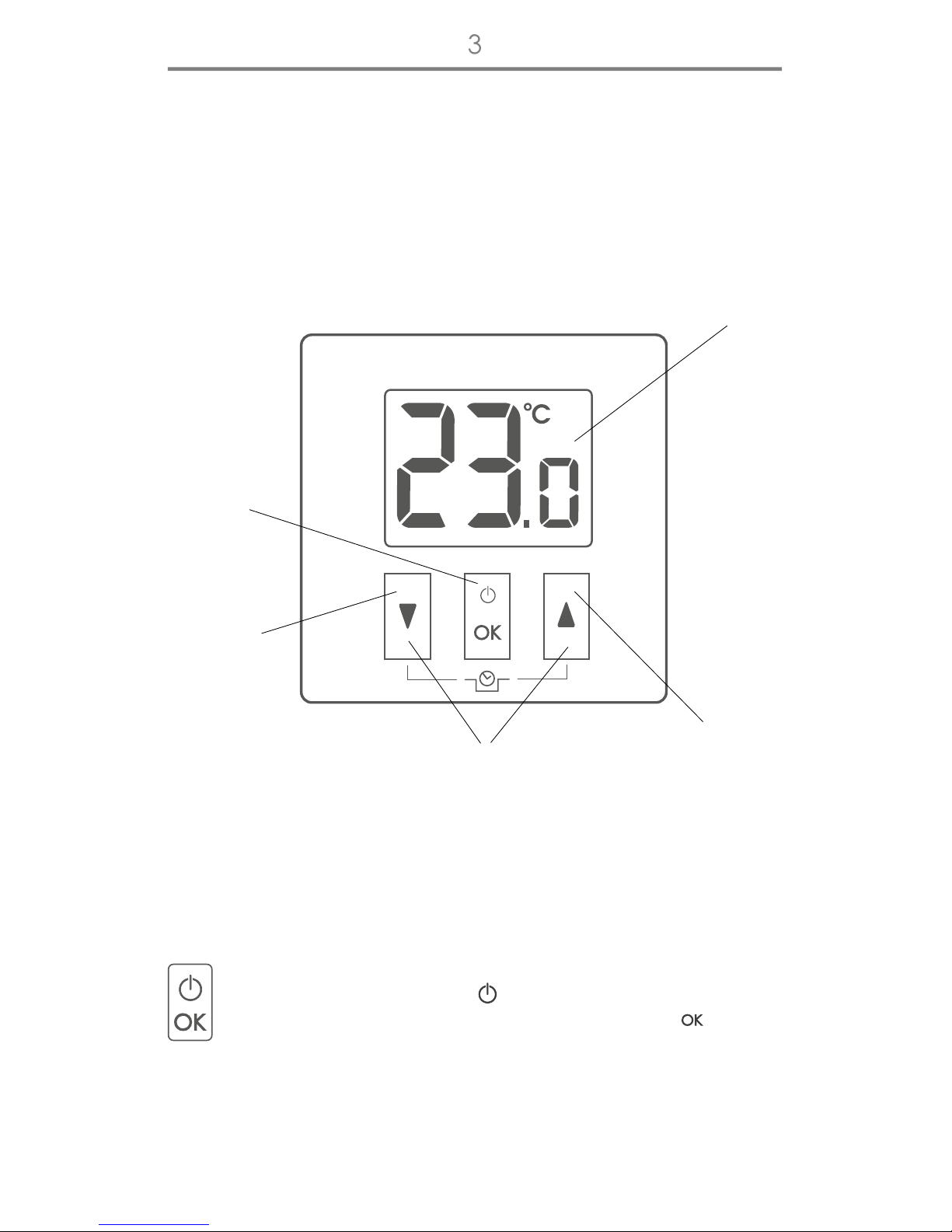
Starting the controller for the first time
Temperature setting
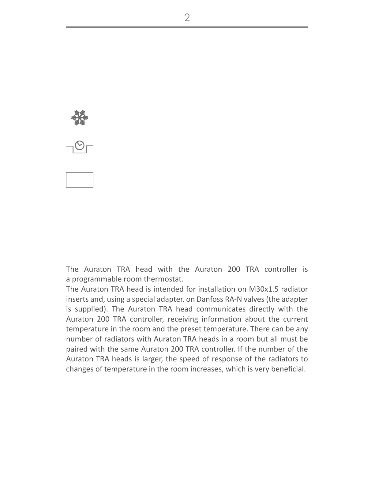
FrostGuard function
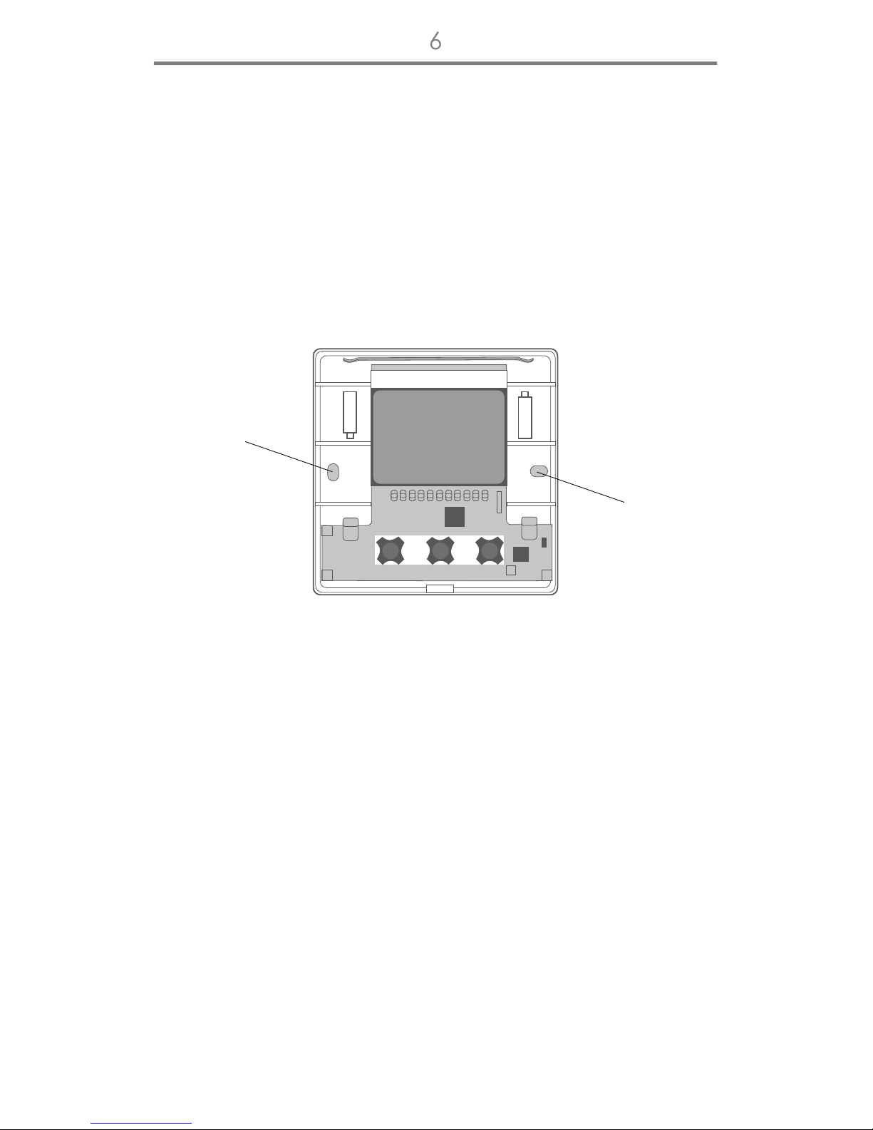
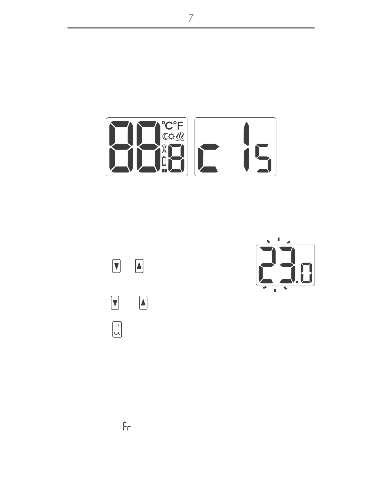
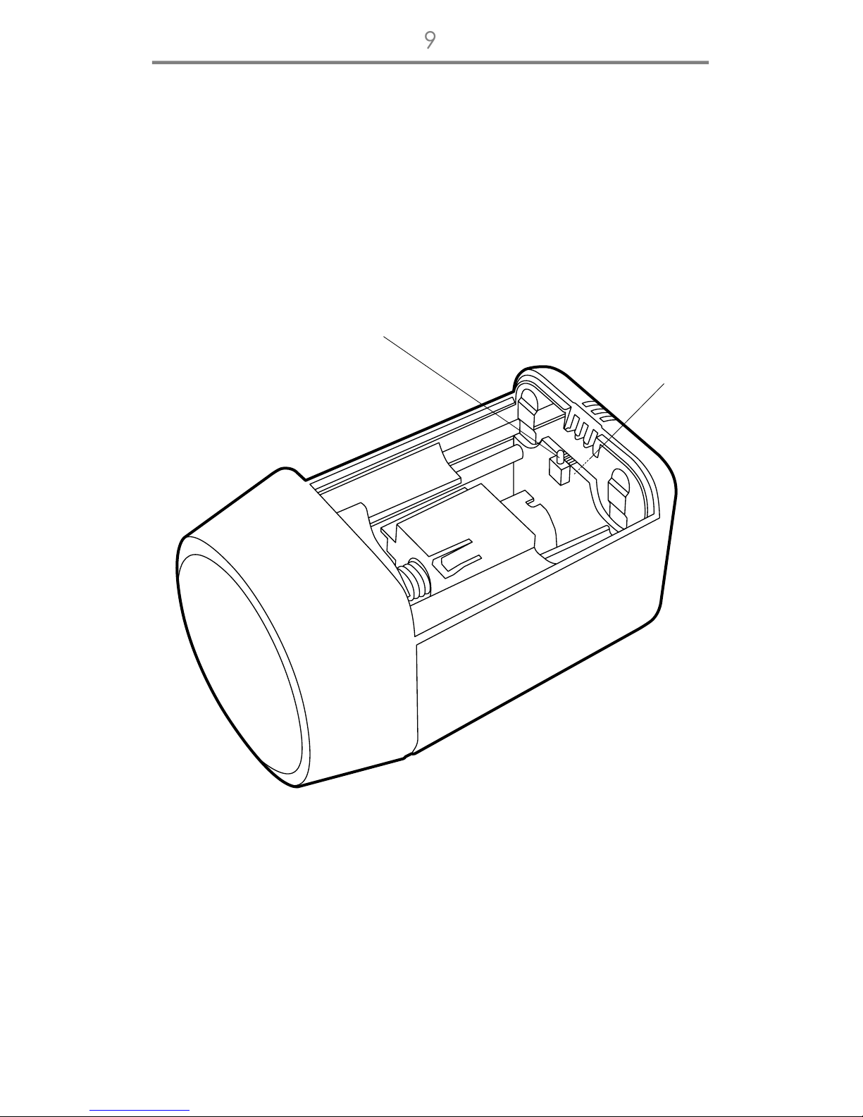
Aer correct installaon on baeries, the LCD will display, for a second,
all segments (display test) followed by the rmware version number.
Aer a while, the current temperature in the room will be displayed. The
controller is ready to use.
To set the desired temperature in normal
operang mode:
1. Press the or key. The segment displaying
temperature will switch to edit mode and start
blinking.
2. With the and keys, set the desired temperature with
the accuracy of up to 0.2°C.
3. Press the <ok key to acknowledge selecon.
AURATON 200 TRA controller features the special FrostGuard funcon
to protect the room from possible freezing. The funcon is acvated
when the controller is switched o.
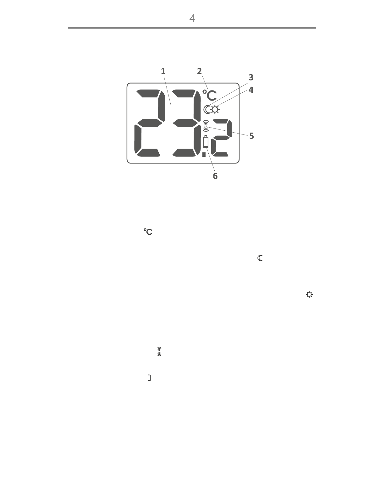
With the controller switched o, when the room temperature drops
to 2°C, the Fr ( ) symbols will appear and signal will be sent to the
receiver to start heang. When the temperature raises to 2.2°C, the
display will turn o again and signal will be sent to the receiver to turn
the heang o.
NOTE: When pressing any funcon key for the rst me, the backlight
is turned on and then the key funcon is acvated.