10
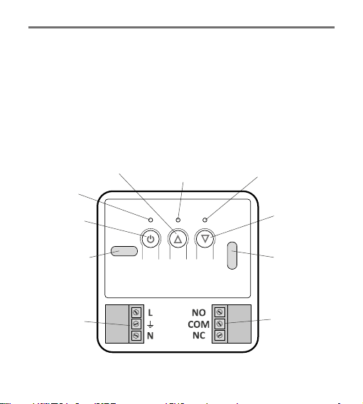
External temperature
sensor
External
temperature sensor Terminal block
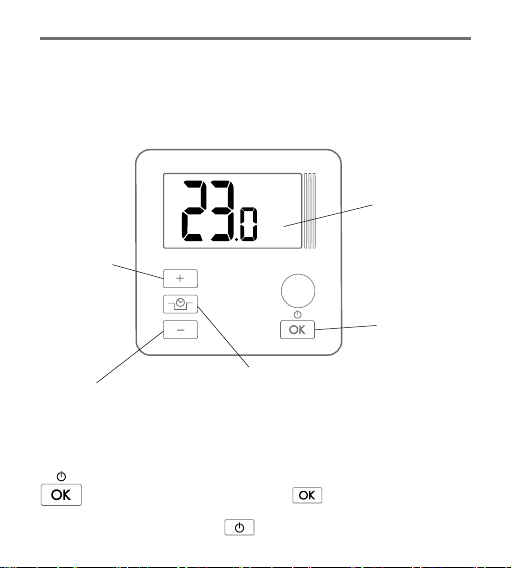
As a standard, aer the baery is put in, the controller without a sensor
connected displays the temperature from the internal temperature sensor.
When the external temperature sensor is connected, the controller automat-
ically reads the values measured by that sensor.
If the external sensor is disconnected or defecve, the control-
ler switches into the emergency mode (dashes are shown as
the temperature value) which results in switching on the relay
and, consequently, the controlled device. In order to leave the
emergency mode, the external temperature sensor must be reconnected or the
controller must be restarted by simultaneously pressing and holding the
and switches for at least 5 seconds. Aer this procedure is completed, the
controller displays the temperature measured by the internal sensor.
Mounting the sensor
Install the sensor on an uncovered outlet pipe connected to the CH boiler
(as close to the boiler as possible). Press the sensor against the tube using
a clamp. It is recommended to wrap the boiler pipe from the boiler to the
sensor with an insulaon material.
If a coal-red boiler and a gas-red boiler work in the same CH system,
the sensor should be installed in a locaon where the two outlets merge
and must be insulated.