AURATON S08 User manual

S08
USER MANUAL
EN
www.auraton.pl

AURATON S08
Bifunctional central heating (CH)
or domestic hot water (DHW) pump controller
3
Can be used as a CH pump controller.
Pumping of water is not recommended when the flame is extinguished
because the air draft into the chimney causes faster cooling of the water
in the boiler faster than in the radiators.
The optimum temperature can be set on the controller's display (most
often 40 °C).
In a CH system with a gas boiler, the temperature set on the controller
must be lower than the temperature set on the CH boiler. If the
temperature is set on the controller above the dew point, it prevents
condensation in the boiler during the heating of the water in the
CH system.
AURATON S08 can be used for automatically switching on and off
circulation pumps depending on the temperature. The controller-pump
assembly forces the water to circulate in the central heating system with a
coal-fired boiler or a gas boiler. The controller's sensor measures the
temperature of the water on the supply side of the CH system. In a CH
system with a coal-fired boiler, the controller switches off the circulation
pump after the flame in the boiler is extinguished.
The range of settings for the CH pumps is from 20 °C to 90 °C.
Can be used as a DHW pump controller.
In domestic hot water (DHW) systems, the controller-pump assembly
forces circulation of water in DHW systems with coal-fired and gas-fired
boilers without systems controlling the operation of the pump.
The controller’s sensor measures the water temperature in the HDW
tank.
AURATON S08 can be used for automatically switching on and off
circulation pumps depending on the temperature.
The range of settings for the HDW pumps is from 20 °C to 90 °C.
The hysteresis (the difference between the switch on temperature and
the shut down temperature) can be set in the range of 2 to 8 °C.
In HDW systems, the controller maintains constant temperature of water
in the tank or in the HDW circuit.
Installation
Mounting the sensor:
źThen install the sensor on an uncovered outlet pipe connected to the
CH boiler (as close to the boiler as possible).
źPress the sensor against the tube using a clamp.
Operation in the CH mode.
źIt is recommended to wrap the boiler pipe from the boiler to the
sensor with an insulation material.
źConnect the brown conductor (phase conductor) to the (L) terminal.
źConnect the yellow or yellow-green conductor (ground or protective
neutral grounding) to the ( ) terminal.#
źAfter the wires have been secured to prevent accidental pulling,
connect the power supply cable to a 230 V/50 Hz power outlet.
Connecting the controller:
NOTE: The sensor must not be immersed in liquids or installed at
flue gas outlets to the stack.
Mounting the controller:
źConnect the blue conductor (zero conductor) to the (N) terminal.
ź The controller must be mounted on a wall or another support using
two screws (the concrete anchors with screws are delivered with the
controller).
źIf a coal-fired boiler and a gas-fired boiler work in the same CH
system, the sensor should be installed in a location where the two
outlets merge and must be insulated.
Operation in the DHW mode.
Connecting the power supply cable to the pump:
ź Install the sensor in the HDW tank.
źThe cables extending from the controller must be fixed to the wall.

54
Description of the controller
+
Temperature,
settings display, etc.;
Operation
indicator
lights;
Function button
/network switch; Function button
/operation modes;
Temperature
sensor;
Power supply
wire
Pump control
output;
First start
2) Software version (e.g. 1.0).
– DHW pump
4) Current temperature of the sensor.
On the left side under the display there is the network switch button ( ). ~
Hold the button for 2 seconds to switch the controller on or off. When the
controller is on, the LED is illuminated red and when it is off, the LED is
illuminated green.
After the controller is switched on, the following sequence of information
is shown on the display:
– CH pump
The sensor is ready to set the appropriate operating temperature.
3) Controller operation modes.
1) Display test (all segments are on).
The temperature value will then blink for 5 seconds on the display. The
appropriate temperature can then be set using the ( – ) or ( + ) button.
After the setting has been performed, the controller automatically stores
this value and the display shows the current sensor temperature.
The temperature setting function can be activated by briefly pressing the
left or right button.
Setting the temperature
The change of the operation mode is saved automatically.
The controller can be set in one of two operation modes.
In order to check the controller’s operation mode, press and hold both
the (–) and the (+) button for 2 seconds. The following information will be
shown on the display:
– controller in the CH pump operation mode;
– controller in the DHW pump operation mode.
The operation mode can be changed by simultaneously pressing and
holding both the (–) and the (+) button for 4 seconds. The display will
show the blinking symbols “ ” or “ ”. When this informationCoO CuU
is displayed, you can change the mode by pressing the (–) or (+) button.
Setting the controllers' mode of operation.

76
The display will show for five seconds the blinking symbols indicating the
controller’s operation mode ( or ) and then, for another [CO] [CU]
5 seconds, the value of the hysteresis setting (e.g. )..[H4]
Example: When setting hysteresis value of, e.g. H4 in the CO mode and
temperature of e.g. 40 °C, the pump will be switched on when
the temperature exceeds 42 °C and will be switched off when
the temperature drops to 38 °C.
When this information is displayed, you can change the set value by
pressing the (–) or (+) button. The range of hysteresis values that can be
set for the controller is from 2°C to 8°C ( to ). After the change is [H2] [H8]
made, it is stored automatically.
The hysteresis can be changed by simultaneously pressing and holding
both the (–) and the (+) button for 4 seconds.
When setting hysteresis value of, e.g. H4 in the CU mode and
temperature of e.g. 40 °C, the pump will be switched off when
the temperature exceeds 42 °C and will be switched on when
Setting of the hysteresis
To do so, press and hold the right button (+) for 2 seconds. Use of this
functionality is indicated by illumination of the right red indicator light
and the ON ( ) characters shown for 10 seconds.[ON]
The controller makes it possible to manually switch on and off the CH or
DHW pump.
NOTE: In the mode of operation, the pump will be on until the [CU]
temperature reaches 90 °C. Once this value is reached, the pump
will switch off. After the temperature drops below 90°C,
the pump is switched on again.
The pump continues to work regardless of the temperature set on the
controller and the actual temperature in the location of the sensor.
In order to switch the pump off, press and hold the right button (+2)
for 2 seconds again.
Manual switching on and off
of the CH or DHW pump
Indication of operation of the pump
Automatic operation Switching on of the pump is indicated by the
of the pump right green indicator light blinking.
Manual operation Switching on of the pump is indicated by the of
the pump right red indicator light blinking.
Disabling the pump alarm
software Version 1.2 and later
The display will show for 5 seconds the blinking operation mode of the
controller (CO or CU) and then for another 5 seconds it will show the value of
hysteresis set (e.g. H4).
To do this, enter the menu of the controller:
When this message is displayed, use buttons (–) or (+) to change this value to
"A 0", which means disabling alarm E 1.
The next setting is for stopping the alarm of E 1 pump; the display will show
blinking message "A 1" (default setting), which indicates active fire alarm.
In specific situations, it is possible to disable the alarm of disconnected or
damaged E 1 pump. It can be done in the case of connecting a pump with a low
power or electronically controlled.
Change the settings by simultaneously pressing and holding buttons (–) and (+)
for 5 seconds.

9
The controller also has the GUARD functions which prevents the stalling
process in the rotor of the pump when it is not in use.
If the pump is not used for a long time, the built-in processor starts the
pump automatically for 30 seconds every 14 days.
NOTE: In order for the system to work after a long period of non-use, the
controller must be switched on at all times.
GUARD function
8
Wiring diagram of the controller in the mode [CO]
(work with a CH pump)
CH boiler
temperature
sensor
pump
L N
yellow-green
wire
blue
wire
brown
wire
+
Switching the controller off
In order to switch the controller off, press and hold for 2 seconds the ( ) [ ~ ]
button; the display is then switched off and the green LED changes its
color to red.
The controller is switched off but the GUARD function continues to be
active.
230V
CO The controller is in the CH mode.
CU The controller is in the DHW mode.
ON The pump has been switched on in the manual mode.
Other information codes
Error information codes
The pump is disconnected or
defective.
No network synchronization
signal that protects the relay
is present.
Sensor short circuit took
place.
Lacking or defective sensor.
Sensor temperature below
25°C.
Sensor temperature above
90°C.
High temperature warning.
CU mode –the pump has been switched off;
waiting for the defect to be repaired
(replacement of a sensor). Once the defect
has been repaired, press any button.
CO mode – the pump has been switched
on.
The pump has been switched off; waiting for
the power supply to be temporarily
disconnected.
CO mode – the pump has been switched on.
CU mode – the pump has been switched
off.
The output power supply is disconnected,
waiting for the defect to be repaired; once
the defect is repaired, press any button.
CO mode – the pump has been switched off.
CU mode – the pump has been switched off;
waiting for the defect to be repaired
(replacement of a sensor); once the defect
has been repaired, press any button.
The pump is stopped; waiting for the defect
to be repaired (higher temperature).
NOTE: The above alarms are signalized with an intermittent acoustic signal until
the relevant defect has been repaired or the controller has been switched
off. After the defect has been repaired, the controller starts normal
operation.
NOTE: In order to switch off the controller during an alarm, press and hold both
the (-) and the (+) button for 2 seconds.

11
Technical data
Operating temperature range: 0 – 40°C
Temperature adjustment range: 20 – 90°C
Temperature measurement range: 2 – 99°C
Power supply voltage: 230 V AC
Hysteresis: 2 – 8°C
Maximum output load: 3 A
Cleaning and maintenance
źDo not touch the device with wet hands. This can lead to electric shock
or serious damage to the device.
źNo not expose the device to excessive impact of smoke or dust.
źAvoid contact of the device with liquids and moisture.
ź Do not touch the display with sharp objects.
źThe outside of the controller must be cleaned with a clean cloth. Do not use
solvents (such as benzene, thinners, or alcohol).
Disposal of the device
The device is marked with a symbol of a crossed waste bin.
Pursuant to European Directive 2002/96/EC and to the Act on
waste electrical and electronic equipment, such mark indicates
that the device, at the end of its service life, must not be disposed
off together with other household waste.
The user is required to deliver it to a waste electrical and
electronic equipment collection point.
10
Wiring diagram of the controller in the mode[CU]
(work with a DHW pump)
Gas boiler
Pump
DHW
sensor
DHW tank
230V
Wiring diagram
with a DHW tank
DHW tank
Pump
230V
temperature sensor
(fix it with a band)
HW
(hot water)
CW
(cold water)
Wiring diagram
of a DHW circuit
+
+

www.auraton.pl
ver. 20181130
Table of contents
Other AURATON Controllers manuals
Popular Controllers manuals by other brands
HID
HID Mercury LP1502 Installations and specifications
Allegion
Allegion interflex IF-4077-8 manual
Grainfather
Grainfather CONICAL FERMENTER PRO Instructions for installing
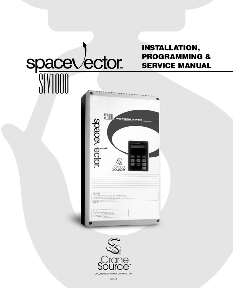
Crane Source
Crane Source Space Vector SFV1000 Installation, Programming & Service manual
Mitsubishi
Mitsubishi Q172CPU user manual

Rosewill
Rosewill RC215 user manual

Bard
Bard TCS22-***-003 Operation manual
Mitsubishi
Mitsubishi MELSEC-F FX3U-4AD installation manual
Cisco
Cisco Catalyst 9800-80 installation guide

SYCLOPE
SYCLOPE EVASION Programming instructions

Mitsubishi Electric
Mitsubishi Electric FX3U-4AD-PNK-ADP user manual
Neptronic
Neptronic TRO24T4XYZ1 Specification and installation instructions
