AURATON 1111 Multi User manual

1111 Multi

AURATON 1111 Multi
AURATON 1111 Multi is a modern, processor-
based controller designed for C.H. and D.H.W.
circulation pumps. It can also be used for a
hydronic fireplace heating system in the C.H.
In addition, the AURATON 1111 Multi can be used
with forced-draft coal- and pulverized coal-fired
C.H. boilers.
AURATON 1111 Multi
1EN

1. Display
The display of the AURATON 1111 MULTI controller divided
into four part, each controlling a separate device.
Part A:
controls the central heating pump "C.H."
Part B:
controls the central heating pump "C.H." and the three-
way valve "Z" or the second central heating pump
(fireplace heating system).
Part C:
controls the domestic hot water pump "D.H.W"
Part D:
controls the fan (blower).
ON
OFF
SMIN
SMIN
A B C D
112
34
1. Display of the temperature measured by individual
sensors.
2. Fan operation time and time between blow-downs
3. User-defined setting
4. Manual operation indicator
EN
AURATON 1111 Multi 2

2. Controls and terminals
Warning: unscrew plastic cover for terminals.
1. A, B, C, D buttons to define individual settings
2. Temperature sensors terminals (SR1, …., Sr3)
3. Actuators terminals (OUT1, …, OUT5)
4. Power supply terminals
5. “+” (plus) button - increase the temperature settings
6. “OK” button - activate the manual mode and accept
7. “-” (minus) button - decrease the temperature settings
8. Main power switch
2.1 General
1. Before cabling the controller remove the protecting
plugs by cutting off.
2. The supplied kit includes only one sensor (about
2.5 m). If it is necessary to increase the controller
functionality, buy an optional temperature sensor
(about 2.5 m).
If the length does not fit, a 15-metre sensor can be
purchased.
A B C D
SR1 SR2 SR3
123 4
5
6
7
8
OUT1 OUT2 OUT3 OUT4 OUT5 IN
AURATON 1111 Multi
3EN

3. Controller in the C.H. mode
(part A of the display)
1. C.H. pump operation indicator
2. C.H. pump sensor indicator
3. manual operation indicator
4. Current C.H. sensor temperature (Sr1)
5. Temperature setting
The pump-controller unit forces the water flow in the C.H.
system with a coal- or gas-fired boiler without the punt
controlling circuit. The controller’s sensor measures the
water temperature o the supply line to the C.H. system.
In the C.H. system with a coal-fired boiler, the controller will
witch off the circulation pump when the flame in the boiler
is extinguished. Water pumping with the flame off is not
recommended as then the water in the boiler would cool
faster than in the radiators. The optimum temperature can
be set on the controller (most often 40oC)
In the C.H. system with a gas-fired boiler, the temperature
must be lower than the temperature set on the C.H. boiler
thermostat. Setting the temperature above the dew point
prevents “sweating” of the boiler while the water in the C.H.
system is heating up.
The controller features also the GUARD, function to
prevent seizure of the pump impeller when the pump is not
used. After the heating season, an additional processor
starts the pump automatically every 14 days for 30
seconds. To make sure the system activates after the
heating season, leave the controller on.
A
1 2 3
4
5
EN
AURATON 1111 Multi 4

3.1 Installation
3.1.1) Mounting the controller
Mount the controller on the wall or a bracket with two
screws (expansion plugs with screws are included in the
controller kit). Fix the conductors from the controller on the
wall with holders.
3.1.2) Mounting the sensor
Before wring cut off the protective plugs. Connect the
temperature sensor to the SR1 terminals on the controller.
Then, install the sensor on an uncovered outlet pipe from
the boiler (as close to the boiler as possible).
NOTE: If the coal- and gas-fired boilers are used for the
same C.H. system, the sensor should be installed where
the two outlets join and then insulated.
3.1.3) Connecting the pump
Connect the pump to the OUT1 terminals on the controller.
Connect the green or yellow-green conductor to the
terminal (protective earth or protective earth and
neutral), connect the blue conductor to the “N” terminal,
and the brown one to the terminal “L”.
3.1.4) Checking the wiring correctness
Check if the wiring is correct and fasten the terminal box
cover with screws.
3.1.5) Connecting the power supply to the controller
When the conductors are secured against accidental
breaking, connect the power cable to the IN terminals (L, ,
N). Then plug into a 230 VAC/50 Hz socket with an
earthing pin.
NOTE: the ambient temperature in the controller location
should not exceed 40oC
AURATON 1111 Multi
5EN

3.2 Operation of the controller
3.2.1) Starting the controller
Put the switch in position “I”. The display will show
the symbol " ", current temperature on the sensor (4)
and the temperature setting (5).
3.2.2) Display description
The indicator in the upper part of the display (4) shows the
current sensor temperature, and the indication in the lower
part (5) shows the temperature setting. Moving blades on
the indicator (1) indicate that the C.H. pump is in operation.
3.2.3) Changing the temperature settings
Press the “A” button below the temperature settings - the
digits will blink and still indicate the current setting. Use the
“+” (increase) or “-“ (decrease) buttons to set the required
temperature. Then confirm by pressing “OK” within 10
seconds. Otherwise, the new set value will not be stored in
the memory and the controller will return to the previous
setting.
3.2.4) Automatic operation
When the settings are made, the controller switches the
pump on and off depending on the set temperature. In the
C.H. system, the pump is activated when the temperature
in the sensor location exceeds the setting by 2oC and is
deactivated when the temperature drops 2oC below the
value set on the controller.
3.2.5) Manual operation - continuous
To activate the C.H. pump manually (irrespective of the
temperature on the SR1 sensor, press and hold the “OK”
button and briefly depress the button “A”. The hand symbol
(3) will appear on the display. To switch off the pump
manually, again press and hold the “OK” button and briefly
depress the button “A”.
NOTE: When only the SR1 sensor is connected, the
remaining functions of the controller are not active, i.e. the
C.H. pump in the fireplace heating system, D.H.W. pump,
and the fan operation are not indicated.
EN
AURATON 1111 Multi 6

3.3 Wiring diagram
A B C D
SR1 SR2 SR3
OUT1 OUT2 OUT3 OUT4 OUT5 IN
BOILER
Pump
L 230VAC
Temperature sensor
(mount with grip band)
4. Controller operating with C.H.
pump and three-way valve “Z” (or
the other C.H. pump (- fireplace
heating system)
(part B of the display)
1. Current C.H. sensor temperature (SR2)
2. C.H. temperature setting in the fireplace heating
system
B
6 5 7
1
2
4
3
AURATON 1111 Multi
7EN

3. temperature setting of three-way valve or the other
C.H. pump
4. C.H. pump operation indicator
5. operation indicator - three-way valve or the other C.H.
pump
6. C.H. pump in manual
7. three-way valve or the other C.H. pump in manual
When operating with a hydronic fireplace, the AURATON
1111 MULTI usestwo controlling outputs:
- to the water pump of the fireplace circuit
- to the valve with an actuator or to the other pump
which is necessary for correct cooperation of the
hydronic fireplace and the C.H. system.
When the controller is energized, the digital sensor
measures the temperature of the water in the fireplace
system and it is possible to divide the water into two
independent channels.
Depending on the water temperature in the fireplace
system, the controller automatically switches on or off the
fireplace C.H. water pump and activates the valve or the
other pump.
The AURATON 1111 Multi features also the GUARD,
function to prevent seizure of the pump impeller when the
pump is not used. After the heating season, an additional
processor starts the pump automatically every 14 days for
30 seconds. To make sure the system activates after the
heating season, leave the controller on.
4.1 Installation
4.1.1) Mounting the controller
Mount the controller on the wall or a bracket with two
screws (expansion plugs with screws are included in the
controller kit). Fix the conductors from the controller on the
wall with holders.
4.1.2) Mounting the sensor
Before wring cut off the protective plugs. Connect the
temperature sensor to the SR2 terminals on the controller.
Then, install the sensor on an uncovered outlet pipe from
the boiler (as close to the boiler as possible). The sensor
shall not be immersed in liquids or placed in combustion
gases outlets to the chimney.
EN
AURATON 1111 Multi 8

4.1.3) Connecting the C.H. pump
Connect the pump to the OUT2 terminals on the controller
(L, , N). Connect the green or yellow-green conductor to
the terminal “ ” (protective earth or protective earth and
neutral), connect the blue conductor to the “N” terminal,
and the brown one to the terminal “L”.
4.1.4) Connecting the valve
Connect the pump to the OUT3 2 terminals on the
controller (L, , N). Connect the green or yellow-green
conductor to the terminal “¤” (protective earth or protective
earth and neutral), connect the blue conductor to the “N”
terminal, and the brown one to the terminal “L”.
4.1.5) Connecting the power supply to the controller
When the conductors are secured against accidental
breaking, connect the power cable to the IN terminals (L, ,
N). Then plug into a 230 VAC/50 Hz socket with an
earthing pin.
NOTE: the ambient temperature in the controller location
o
should not exceed 40 C
4.2 Operation of the controller
4.2.1) Starting the controlle
Put the switch in position “I”. All display segments will
light up for about 2 seconds. Then, the display will show
the current temperature on the sensor.
4.2.2) Settings range
The temperature (from 0oC do 99oC) is measured by the
SR2 sensor. The C.H. pump is controlled by means of the
OUT 2 output. The three-way valve or the other C.H. pump
are controlled by means of the OUT 3 output. The settings
range for the C.H. pumps and the three-way valve (or the
other C.H. pump) is 10oC do 90oC, the hysteresis
(temperature difference between the activation and
deactivation) is 4oC.
4.2.3) Changing the temperature settings
Press the “B” button below the temperature settings - the
temperature setting indicator for the fireplace heating
system will start to blink. Then, use the “+” (increase) or “-“
(decrease) buttons to set the required temperature.
AURATON 1111 Multi
9EN

Confirm by pressing “OK” within 10 seconds. Otherwise,
the new set value will not be stored in the memory and the
controller will return to the previous setting.
4.2.4) Automatic operation
When the settings are made, the controller switches the
pump on and off depending on the set temperature. In the
C.H. system, the pump and the valve are activated when
the temperature in the sensor location exceeds the setting
by 2oC, and are deactivated when the temperature drops
2oC below the value set on the controller.
4.2.5 Manual operation - continuous
Step 1:
To activate the C.H. pump manually (irrespective of the
temperature on the SR2 sensor), press and hold the “OK”
button and briefly depress the button “B”. The hand symbol
(3) will appear on the display (to the left of the C.H.
pump operation pictogram in the fireplace heating mode).
Step 2:
If within 2 seconds the “B” button is pressed again (with the
“OK” depressed), the manual mode “ ” for the C.H. pump
will be deactivated, and simultaneously the manual mode
for the tree-way valve (or the other C.H. pump) will be
activated - the hand symbol to the right.
Step 3:
If within the following 2 seconds the “B” button is pressed
again (with the “OK” depressed), the manual mode will be
activated for the C.H. pump, the tree-way valve (or the
other C.H. pump) in the fireplace heating system (“ ” and
“ ”).
Step 4:
If within the following 2 seconds the “B” button is pressed
again (with the “OK” depressed), the manual mode will be
deactivated for the C.H. pump, the tree-way valve (or the
other C.H. pump) in the fireplace heating system.
EN
AURATON 1111 Multi 10

4.5 Wiring diagram
Typical wiring diagram. The diagram below is simplified ad
does not include all components necessary for the correct
operation of the system.
A B C D
SR1 SR2 SR3
OUT1 OUT2 OUT3 OUT4 OUT5 IN
1
7
2345
8
9
6
230V
1. Hydronic fireplace
2. Cut-off valve
3. pump
4. exchanger
5. three-way valve with actuator
6. heat receiver/ radiator
7. compensating vessel
8. temperature sensor
9. C.H. boiler
NOTE: When only the SR2 sensor is connected, the
remaining functions of the controller are not active, i.e. the
C.H. pump, D.H.W. pump, and the fan operation are not
indicated.
AURATON 1111 Multi
11 EN

5. Controller in the D.H.W. mode
(part C of the display)
1. Current C.H. sensor temperature (Sr3)
2. D.H.W. temperature setting
3. D.H.W. over C.H. priority indicator (frame)
4. D.H.W. pump operation indicator
5. D.H.W. manual pump operation indicator
C
3 4 5
1
2
The electronic pump controller AURATON 1111 MULTI can
also be used for automatic control of the circulation pump
in the domestic hot water system (D.H.W.).
In the D.H.W. system the user maintains the constant
temperature of the water in the storage vessel or in the
D.H.W. circuit. If the “C” button is pressed for about
2 seconds, the :frame” (3) (priority of D.H.W. over C.H.) will
be activated.
If the “C” button is pressed for about 2 seconds, the frame
will be deactivated (no priority of D.H.W. over C.H.).
NOTE:the priority of D.H.W. over C.H. is active only in the
manual operation of the D.H.W. pump (indicator 5).
EN
AURATON 1111 Multi 12

5.1 Operation with deactivated priority of D.H.W.
over C.H.
Operation with deactivated priority of D.H.W. over C.H.
If the priority of D.H.W. over C.H. is deactivated, the start of
the pump in ten domestic hot water system depends only
on the setting and the temperature on the SR3 sensor
which is installed in they storage vessel.
5.1.1) Settings range
The temperature (from 0oC do 99oC) is measured by the
SR3 sensor. The C.H. pump is controlled by means of the
OUT 4 output.
The three-way valve or the other C.H. pump are controlled
by means of the OUT 3 output. The settings range for the
D.H.W. pump is 10oC do 90oC. the hysteresis (temperature
difference between the activation and deactivation) is 3oC.
5.1.2) Programming the D.H.W. functions
Press once briefly the “C’” button - the factory setting 60oC
will start to blink. Then use the “+” or “-“ buttons to set the
required temperature.
confirm by pressing “OK” within 10 seconds. Otherwise,
the new set value will not be stored in the memory and the
controller will return to the previous setting. When new
settings are stored in the memory, the controller exits the
settings mode and enter the normal operation mode (the
blinking of the temperature settings stops).
The controller will deactivate the D.H.W. pump (OUT4) if
the temperature on the SR3 sensor exceeds the set value
by 1oC and will activate the pump if the temperature drops
by 2oC below the setting.
5.1.3) Manual operation - continuous
To activate the C.H. pump manually (irrespective of the
temperature on the SR3 D.H.W. sensor), press and hold
the “OK” button and briefly depress the button “C”. The
hand symbol will appear on the display. To switch off
the D.H.W. pump manually, again press and hold the “OK”
button and briefly depress the button “C”.
NOTE: If the temperature on the T3 sensor (RS3) exceeds
90oC, the D.H.W. pump will switch off, preventing
excessive temperature of the water in the tank.
AURATON 1111 Multi
13 EN

5.2 Operation with activated priority of D.H.W.
over C.H.
If the priority of D.H.W. over C.H. is activated, the start of
the pump in ten domestic hot water system depends not
only on the setting and the temperature on the SR3 sensor
which is installed in they storage vessel, but also on the
temperature on the SR3 sensor (C.H.).
If the priority of D.H.W. over C.H. is activated, and the
situation commands that both the D.H.W. and C.H. pumps
should operate simultaneously, (provided the SR1 sensor
and the power supply to the C.H. pump [OUT1] are
connected), the D.H.W. pump has the priority.
Operation: the domestic hot water pump is activated forts
and runs until the required temperature is achieved. Then,
the C.H. pump is activated. The next function of the priority
of D.H.W. over C.H. is that if the temperature on the SR1
(C.H.) sensor is lower than the temperature on the SR3
sensor (D.H.W.), the D.H.W. pump will not start to protect
the water in the D.H.W. tank from excessive cooling.
5.2.1) Manual operation - continuous
To activate the circulation pump manually (irrespective of
the temperature on the SR3 D.H.W. sensor), first
deactivate the priority function and then follow the
instructions given in 5.1.3.
5.3 Installation
5.3.1) Mounting the controller
Mount the controller on the wall or a bracket with two
screws (expansion plugs with screws are included in the
controller kit). Fix the conductors from the controller on the
wall with holders.
5.3.2) Mounting the sensor
Connect the temperature sensor to the SR3 terminals on
the controller. Then, install the sensor in the domestic hot
water storage vessel. The sensor shall not be immersed in
liquids or placed in combustion gases outlets to the
chimney. Maximum temperature measurement: 99oC.
EN
AURATON 1111 Multi 14

5.3.3) Connecting the D.H.W. pump
Connect the pump to the OUT4 terminals on the controller
(L, , N). Connect the green or yellow-green conductor to
the terminal “ ” (protective earth or protective earth and
neutral), connect the blue conductor to the “N” terminal,
and the brown one to the terminal “L”.
5.3.4) Connecting the power supply to the controller
When the conductors are secured against accidental
breaking, connect the power cable to the IN terminals (L, ,
N). Then plug into a 230 VAC/50 Hz socket with an
earthing pin.
NOTE: the ambient temperature in the controller location
should not exceed 40oC.
5.4 Operation of the controller
5.4.1) Starting the controller
Put the switch in position “I”. All display segments will
light up for about 2 seconds.
Then, the display will show the current temperature on the
sensor.
5.4.2) Changing the temperature settings
Press the “C” button briefly - the temperature setting
indicator D.H.W. will start to blink.
Then, use the “+” (increase) or “-“ (decrease) buttons to set
the required temperature.
Confirm by pressing “OK” within 10 seconds. Otherwise,
the new set value will not be stored in the memory and the
controller will return to the previous setting.
AURATON 1111 Multi
15 EN

5.5 Wiring diagram
5.5.1) In the D.H.W. circuit
A B C D
SR1 SR2 SR3
OUT1 OUT2 OUT3 OUT4 OUT5 IN
D.H.V.
storage tank
Pump
L 230VAC
Temperature sensor
(mount with grip band)
CW ZW
5.5.2) with the D.H.W. storage tank
A B C D
SR1 SR2 SR3
OUT1 OUT2 OUT3 OUT4 OUT5 IN
Gas boiler
Pump
L 230VAC
D.H.V. temperature sensor
D.H.V.
storage tank
NOTE: When only the SR3 sensor is connected, the remaining functions of the controller are not active, i.e. the C.H. pump
(SR1), C.H. pump and the three-way valve, and the fan operation are not indicated.
EN
AURATON 1111 Multi 16

6. Fan control
(part D of the display)
1. Fan operation indicator
2. Manual fan operation indicator
3. Fan operation counter and blow-down intervals, and the
“HI”, “LO” and “EE” signalling
4. Time units (S = seconds, MIN = minutes)
D
12
3ON
OFF
SMIN
SMIN
4
5
67
5. Fan operation (ON) and intervals between blow-downs
(OFF).
6. Temperature setting below which the fan operation is
triggered
7. Time units
AUARTON 1111 MULTI , is a modern, processor-based
controller which can also be used with forced-draft coal-
and pulverized coal-fired C.H. boilers. Depending on the
water temperature in the boiler, the controller automatically
switches on or off the C.H. water pump and activates the
blower situated over the boiler furnace.
A digital controller sensor measures the water temperature
to control he pump and the blower.
The AURATON1111 MULTI features also the GUARD
function to prevent seizure of the pump impeller when the
pump is not used
AURATON 1111 Multi
17 EN

6.1 Instalacja
6.1.1) Mounting the controller
Mount the controller on the wall or a bracket with two
screws (expansion plugs with screws are included in the
controller kit).
Fix the conductors from the controller on the wall with
holders.
6.1.2) Mounting the sensor
Connect the temperature sensor to the SR1 terminals on
the controller. Then, install the sensor on the specified area
of the boiler.
The sensor shall not be immersed in liquids or placed in
combustion gases outlets to the chimney. Maximum
measured temperature is 99oC.
6.1.3) Connecting the pump
Connect the C.H. pump to the OUT1 terminals on the
controller. Connect the green or yellow-green conductor to
the terminal “ ” (protective earth or protective earth and
neutral), connect the blue conductor to the “N” terminal,
and the brown one to the terminal “L”.
6.1.5) Connecting the power supply to the blower
Connect the blower to the OUT5 (L, , N) terminals on the
controller.
Connect the green or yellow-green conductor to the
terminal “ ” (protective earth or protective earth and
neutral), connect the blue conductor to the “N” terminal,
and the brown one to the terminal “L”.
6.1.6) Connecting the power supply to the controller
When the conductors are secured against accidental
breaking, connect the power cable to the IN terminals (L, ,
N). Then plug into a 230 VAC/50 Hz socket with an
earthing pin.
NOTE: the ambient temperature in the controller location
should not exceed 40oC.
18
EN
AURATON 1111 Multi

6.2 Operation of the controller
6.2.1) Załączanie sterownika
Starting the controller Put the switch in position “I”. All
display segments will light up for about 2 seconds. Then,
the display will show the current temperature on the
sensor.
6.2.2) Settings range
NTemperature settings (from 10oC do 90oC).
The operation time and blow-down interval settings: from
0 to 59 seconds, and then from 1 do 99 minutes.
The fan is controlled by means of the OUT 5 output. The
set temperature refers to the temperature measured by the
SR1 sensor (C.H.). The hysteresis (temperature difference
between the activation and deactivation) is 4oC.
6.2.3) Changing the temperature settings
Press the “D” button briefly - the factory (default) set value
of 50oC will start to blink. Then, use the “+” (increase) or “-“
(decrease) buttons to set the required temperature above
which the fan will be switched on and off.
Confirm by pressing “OK” within 10 seconds. Otherwise,
the new set value will not be stored in the memory and the
controller will return to the previous setting.
6.2.4) Changing the operation time and operation
cycles
When the “D” button is depressed once, the fan triggering
temperature will start to blink.
If the “D” button is depressed again within 10 seconds, you
enter into the fan operation cycles programming mode
(blow-down duration times, the default value is 15
seconds). Use the “+” (increase) or “-“ (decrease) buttons
to set the required value (when you exceed 59 seconds,
the time will automatically be displayed in minutes).
If the “D” button is depressed again within 10 seconds, you
enter into the fan operation cycles programming mode
(intervals between blow-downs, the default value is 5
minutes).
AURATON 1111 Multi
19 EN
Table of contents
Other AURATON Controllers manuals
Popular Controllers manuals by other brands
Danfoss
Danfoss EKE 1A installation guide

IBM
IBM Netfinity ServeRAID-3H Installation and user guide

Sollae Systems
Sollae Systems CIE-H14G user manual

AutomationDirect
AutomationDirect Stellar SR55 Series user manual
Heath Zenith
Heath Zenith Dual Brite SL-5512 user manual
Delta
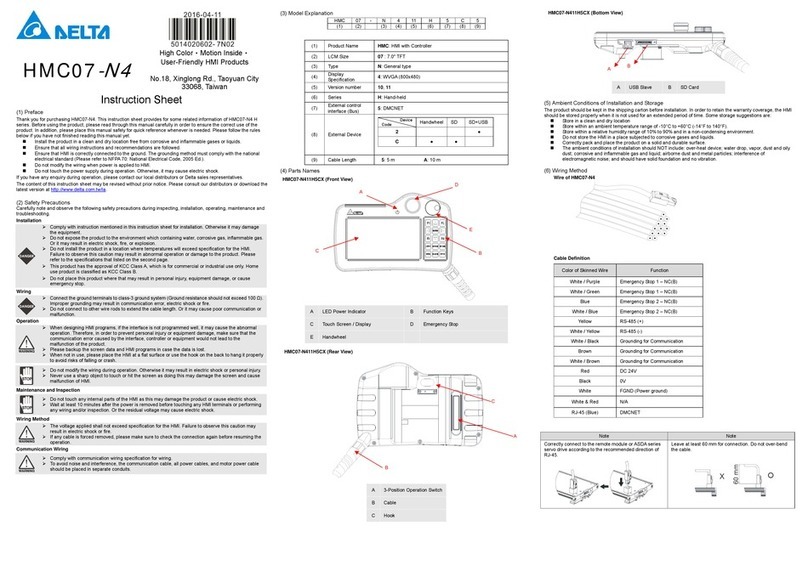
Delta HMC07-N4 instruction sheet
