AUREL RX-4MR50-SMD User manual
RX-4MR50-SMD
---------------------------------------------------------------------------------------------------------------------------------------------------
Instruction Manual
Technical features are subject to change without notice. AUR°EL S.p.A does not feel responsible for any da age caused by the device’s isuse.
-----------------------------------------------------------------------------------------------------------------------------
----------------------------------
------
AUREL S.p.A.
Via Foro dei Tigli, 4 - 47015 Modigliana (FC) – ITALY
Tel.: +39.0546.941124 Fax: +39.0546.941660
01/08/2018 - Rev.A
Pag 1 di 6
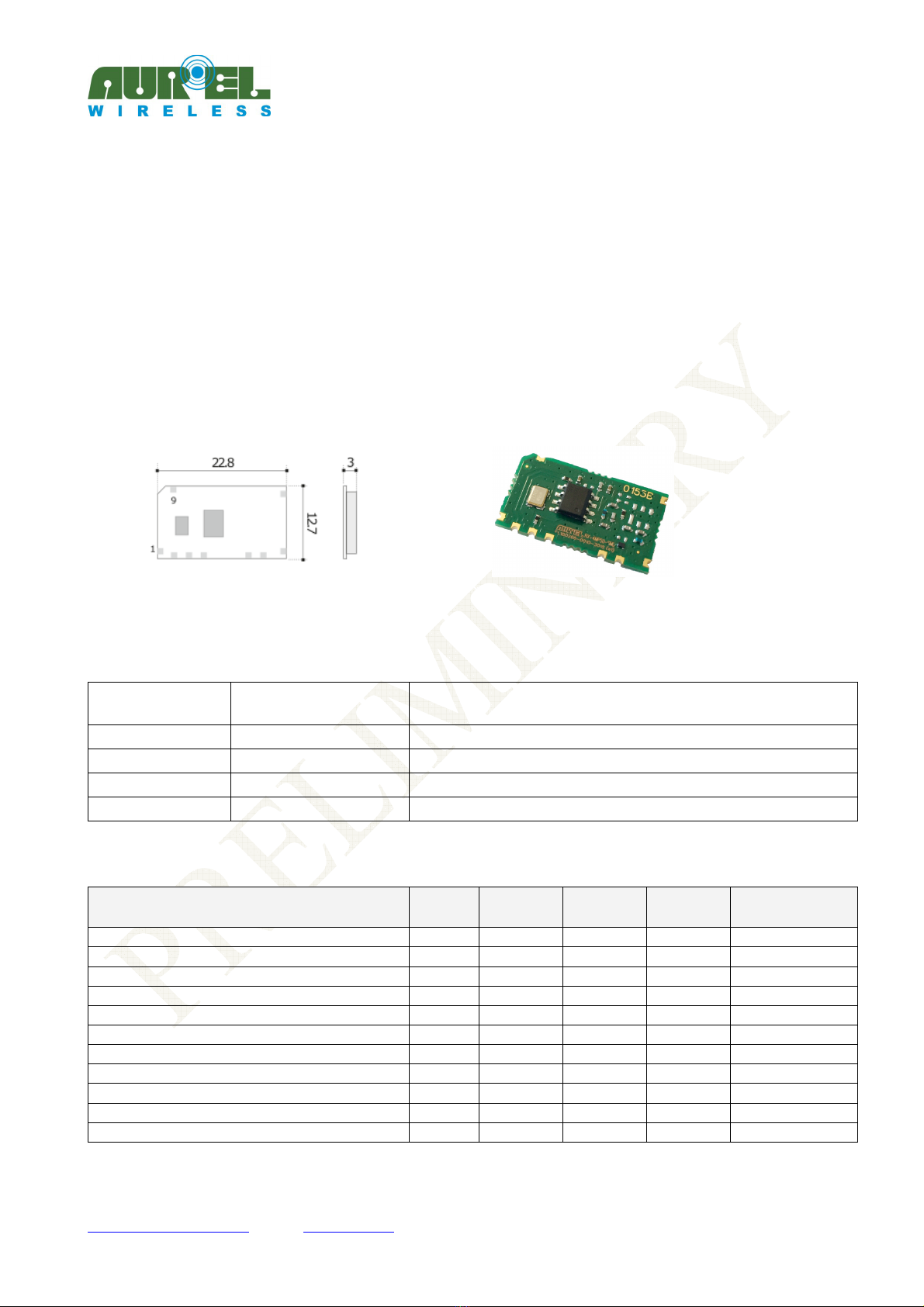
Band pass filtered Super Het Receiver 433.9 MHz
Low cost OOK receiver working at 433,92MHz with band pass filter, co pliant with RED (Radio Equip ent
Directive 2014/53/EU) and in particular with har onics standards:
•EN 301 489-3 : V2.1.1 (final draft)
•EN 300 220-2 : V3.1.1
ESD antenna protection in co pliance with EN610000-4-2.
PIN-OUT
CONNECTIONS
Pin 1-5-7-8-9 GND GND Connections. To be externally connected to a single
ground plate.
Pin +Vcc Connection to the positive pole of supply.
Pin 3 Data-Out Data output fro the receiver. Load higher than 1KΩ.
Pin 4 NC Not connected
Pin 6 Antenna Antenna input, i pedance 50Ω.
Technical features RX-4MR50
Min Tipic Max Unit Remarks
Supply voltage 3 5 5,5 Vdc
Supply current 4,1 4,3 4,6 A
Reception frequency 433,92 MHz
RF sensitivity -112 -114 dB See note 1
IF Bandwidth -3dB 420 KHz
RF power on 50Ω pin ant. -60 dB
Square wave output 0,020 1 5 KHz
Output high voltage Vcc-0,6 Vcc-0,1 V
Output low voltage GND GND+0,4 V
Switch on time 4 s
Operating temperature range -20 +85 °C
NOTE 1:
RF generator with 100% odulation.

RX-4MR50-SMD
---------------------------------------------------------------------------------------------------------------------------------------------------
Instruction Manual
Technical features are subject to change without notice. AUR°EL S.p.A does not feel responsible for any da age caused by the device’s isuse.
-----------------------------------------------------------------------------------------------------------------------------
----------------------------------
------
AUREL S.p.A.
Via Foro dei Tigli, 4 - 47015 Modigliana (FC) – ITALY
Tel.: +39.0546.941124 Fax: +39.0546.941660
01/08/2018 - Rev.A
Pag 2 di 6
Pin 6
The declared technical features have been obtained by applying the following testing syste :
Picture 1: Measure ent of sensitivity
Device usage
In order to obtain the perfor ances described in the technical specifications and to co ply with the
operating conditions, which characterize the Certification, the trans itter has to be ounted on a printed
circuit taking into account the following.
Power Supply:
1. RX-4MR50-SMD ust be supplied fro very low voltage safety source protected against the short circuits.
Maxi u voltage variations allowed: 3 ÷ 5,5 V. However it is preferable to aintain a stable voltage to a
predeter ined value in the range of voltage as specified above, using a "fast transient response" voltage
regulator.
2. Connect electrolytic capacitor 100uF, low ESR, close to pin 2 (+Vcc).
Ground:
The ground ust surround at the best the welding area of the odule and ust also be realized in the
lower face of the PCB in order to obtain the opti al result, with the through holes connecting the two
ground planes approxi ately each 15 .
It ust be properly di ensioned, especially in the antenna connection area, in case a radiating whip
antenna is fitted in it (an area of approxi ately 50 radius is suggested).
Antenna:
1. A whip antenna, 16,5 long and approxi ately 1 dia, brass or copper wire ade, ust be
connected to the RF input of the receiver (pin 6).
2. The antenna body ust be keep straight as uch as possible and it ust be free fro other circuits or
etal parts (5c ini u suggested distance).
3. It can be utilized either vertically or horizontally, provided that a good ground plane surrounds the
connection point between antenna and trans itter output.
50 Ohm line:
1. It ust be the shortest as possible.
2. 1,8 wide for 1 thick FR4 printed circuits and 2,9 wide for 1,6 thick FR4 printed circuits.
On the sa e side, it ust be kept 2 away fro the ground circuit.
3. On the opposite side a ground circuit area ust be present.
Digital Encoder
HCS 300
RF Generator: frequency 433.9 MHz
AM Modulation OUT RF
RX
-
4MR50
-
SMD
Decoder
HCS
Pin 3
LED RX OK

RX-4MR50-SMD
---------------------------------------------------------------------------------------------------------------------------------------------------
Instruction Manual
Technical features are subject to change without notice. AUR°EL S.p.A does not feel responsible for any da age caused by the device’s isuse.
-----------------------------------------------------------------------------------------------------------------------------
----------------------------------
------
AUREL S.p.A.
Via Foro dei Tigli, 4 - 47015 Modigliana (FC) – ITALY
Tel.: +39.0546.941124 Fax: +39.0546.941660
01/08/2018 - Rev.A
Pag 3 di 6
Antenna connection:
1. It ay be utilized as the direct connection point for the radiating whip antenna.
2. It can bear the connection of the central wire of a 50Ω coaxial cable. Be sure that the braid is welded to
the ground in a close point.
N.B.: As an alternative to the a. . antenna it is possible to utilize the whip odel anufactured by Aurel
(see related Data Sheet and Application Notes).
By fitting whips too different fro the described ones, the EEC Certification is not assured.
Other components:
1. Keep the receiver separate fro all other co ponents of the circuit ( ore than 5 ).
2. Keep particularly far away and shielded all icroprocessors and their clock circuits.
3. Do not fit co ponents around the 50Ω line. At least keep the at 5 distance.
If the antenna connection is directly used for a radiating whip connection, keep at least a 5c radius free
area. In case of coaxial cable connection 5 radius will suffice.
Soldering and assembling layout SMD
Picture : Reco ended layout for Host board
In order to ensure the correct asse bly of the odule you are required to apply a production process
observing carefully the following reco endations:
Soldering paste: Use soldering paste as SAC305 (96,5% Sn, 3% Ag, 0,5% Cu), with a thickness> 150u .
Asse bly: the odule can be asse bled with auto atic achine by using a suction cup tool, applied on
bigger integrated circuit
RX-4MR50-SMD
---------------------------------------------------------------------------------------------------------------------------------------------------
Instruction Manual
Technical features are subject to change without notice. AUR°EL S.p.A does not feel responsible for any da age caused by the device’s isuse.
-----------------------------------------------------------------------------------------------------------------------------
----------------------------------
------
AUREL S.p.A.
Via Foro dei Tigli, 4 - 47015 Modigliana (FC) – ITALY
Tel.: +39.0546.941124 Fax: +39.0546.941660
01/08/2018 - Rev.A
Pag 4 di 6
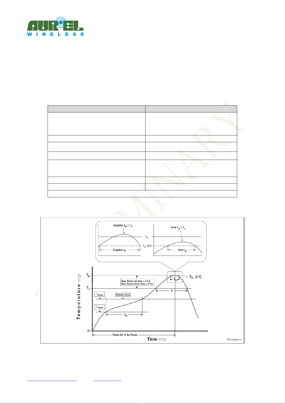
Soldering: the odule can be soldered on host board, through a reflow profile for Lead-free co ponents.
Jedec standard “J-STD-020E”
Standard Jedec “J-STD-020E” defines te peratures and exposure ti es, is attached below graph and profile
table ti e / te perature reco ended for the purpose.
For host that provide ore reflow cycles it is reco ended to perfor the soldering of the odule at the
end of the soldering cycle, taking care to li it excessive vibrations during the ter inal phase of reflow
soldering paste.
Profile Feature
Pb
-
Free Assembly
Preheat/Soak
Temperature Min (T
smin
)
Temperature Max (T
smax
)
Time (t
s
) from (T
smin
to T
smax
)
150 °C
200 °C
60-140 seconds
Ramp-up rate (T
L
to T
p
) 2 °C/second max.
Liquidous temperature (T
L
)
Time (t
L
) maintained above T
L
217 °C
60-150 seconds
Peak package body temperature (T
p
) 240°
Time (t
p
)* within 5 °C of the specified classification
temperature (T
c
), see Figure 9.
30* seconds
Ramp-down rate (T
p
to T
L
) 6 °C/second max.
Time 25 °C to peak temperature 5 minutes max.
* Tolerance for peak profile temperature (T
p
) is defined as a supplier minimum and a user maximum.
Table 1: Detailed ti e / te peratures profile for soldering RX-4MR50-SMD
Picture 3: Soldering profile for RX-4MR50-SMD
RX-4MR50-SMD
---------------------------------------------------------------------------------------------------------------------------------------------------
Instruction Manual
Technical features are subject to change without notice. AUR°EL S.p.A does not feel responsible for any da age caused by the device’s isuse.
-----------------------------------------------------------------------------------------------------------------------------
----------------------------------
------
AUREL S.p.A.
Via Foro dei Tigli, 4 - 47015 Modigliana (FC) – ITALY
Tel.: +39.0546.941124 Fax: +39.0546.941660
01/08/2018 - Rev.A
Pag 5 di 6
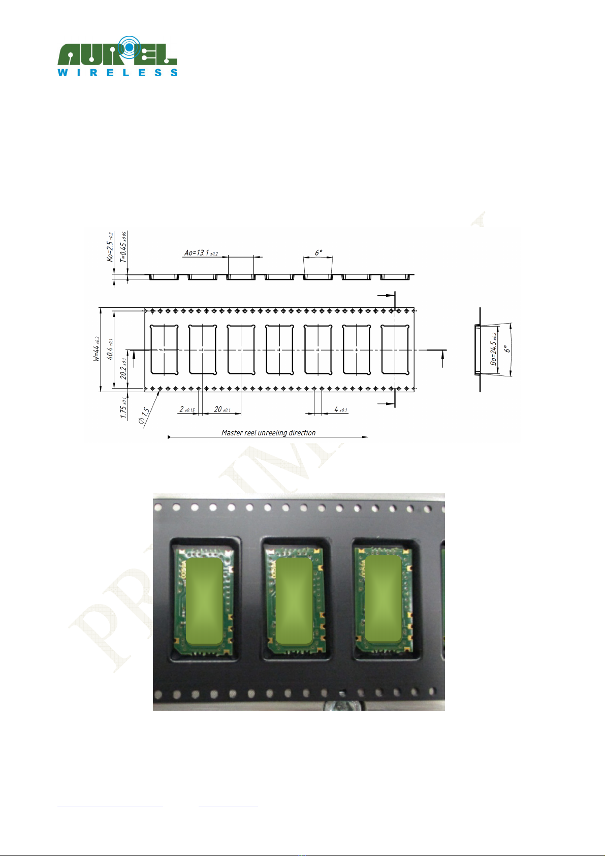
Specifications Packaging Tape and Reel
RX-4MR50-SMD is packed in Tape and Reel co posed by an e bossed carrier tape and antistatic cover
tape.
In this way the odules are ESD protected and can be handled by achines for the auto atic asse bly of
SMD co ponents.
Picture 4: Tape and Reel drawing (in )
Picture 5: External aspect of the e bossed

RX-4MR50-SMD
---------------------------------------------------------------------------------------------------------------------------------------------------
Instruction Manual
Technical features are subject to change without notice. AUR°EL S.p.A does not feel responsible for any da age caused by the device’s isuse.
-----------------------------------------------------------------------------------------------------------------------------
----------------------------------
------
AUREL S.p.A.
Via Foro dei Tigli, 4 - 47015 Modigliana (FC) – ITALY
Tel.: +39.0546.941124 Fax: +39.0546.941660
01/08/2018 - Rev.A
Pag 6 di 6
Reference Rules
RX-4MR50-SMD receiver is co pliant with the European set of rules EN 300 220-2, and EN 301 489-3.
The receiver ust be supplied by a very low voltage safety source protected against short circuits.
The usage of the odule is foreseen inside enclosures that guarantee the EN 61000-4-2 nor ative not
directly applicable to the odule itself.
This device is co pliant with EN 62479, connected to the electro agnetic field hu an exposition, if used
with te poral duty cycle not higher than 10% like foreseen in CEPT 70-03 reco endation.
Reference curves
TBD
Picture 6: Supply current – Power supply
TBD
Picture 7: Supply current - Te perature
TBD
Picture 8: Sensitivity - Te perature
User manual revision summary
Release date
Revision user
manual Changes from the previous revision
01/08/2018 Preli inary
This manual suits for next models
1
Table of contents
Other AUREL Receiver manuals


Popular Receiver manuals by other brands


AIRTRONICS
AIRTRONICS RX-472 user guide

Sony
Sony STR-DA6400ES - Multi Channel Av Receiver Network guide

OPW
OPW 1611 SERIES Installation and maintenance instruction

SABINE
SABINE SW71-NDR user guide

Fanimation
Fanimation WFR6236 SPECIFICATION AND INSTRUCTION SHEET

Pioneer
Pioneer Elite SC-25 operating instructions


