AUREL TX 434 SMALL IA User manual

TX 434 SMALL IA
---------------------------------------------------------------------------------------------------------------------------------------------------
Instruction Manual
Technical features are subject to change without notice. AUR°EL S.p.A does not feel responsible for any da age caused by the device’s isuse.
-----------------------------------------------------------------------------------------------------------------------------
------------------------------------
----
AUREL S.p.A.
Via Foro dei Tigli, 4 - 47015 Modigliana (FC) – ITALY
Tel.: +39.0546.941124 Fax: +39.0546.941660
19/09/2018 - Rev.A
Pag 1 di 9
433 MHz ASK TRANSMITTER
SMT Trans itter with integrated antenna, operating at 434 MHz in ASK odulation. Ideal to be integrated in
Key fobs, s all hardware and portable devices.
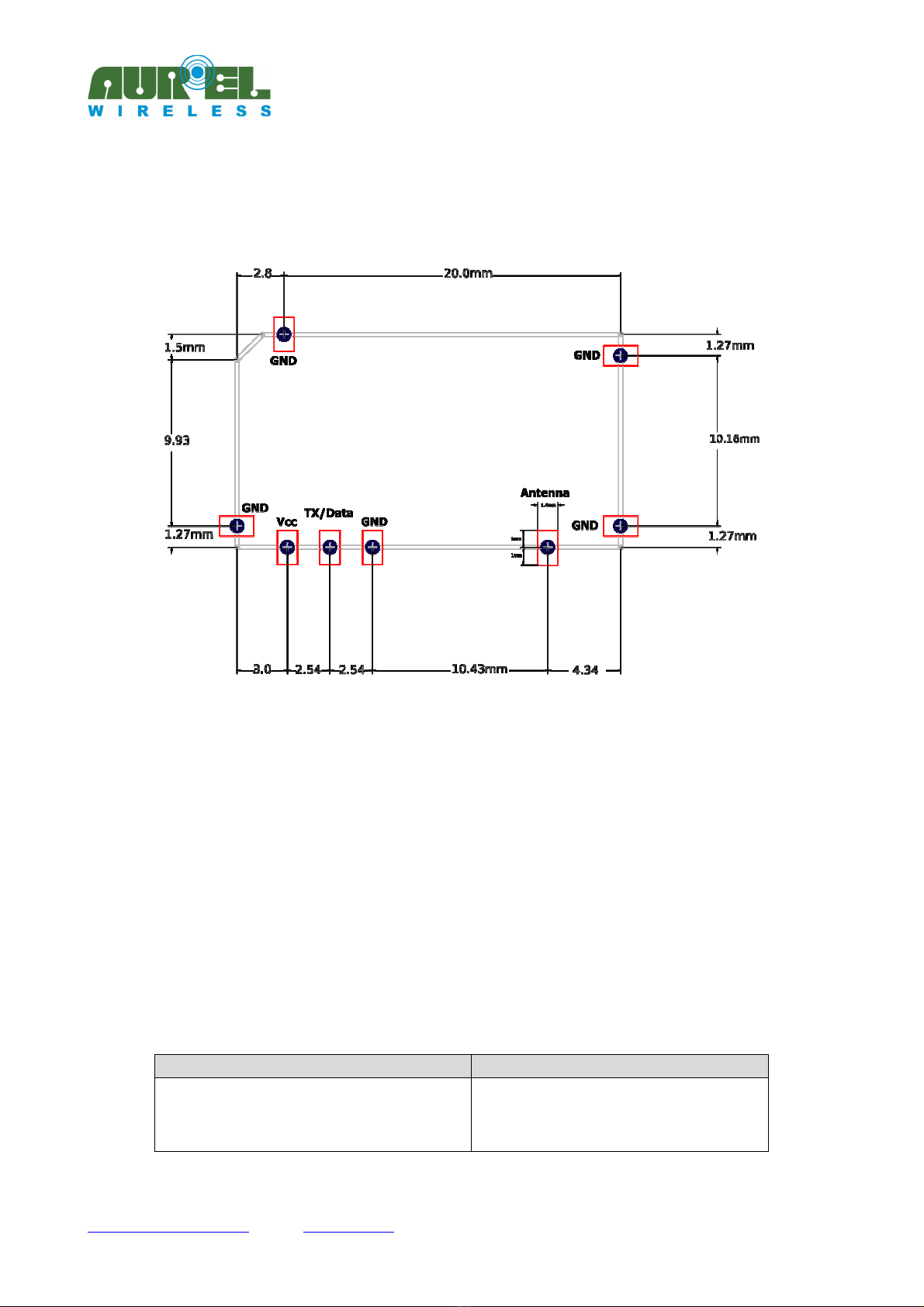
PIN-OUT
CONNECTIONS
Pin -4-6-7-8 GND GND Connections. To be externally connected to a single
ground plate.
Pin 2 +Vcc Connection to the positive pole of supply.
Pin 3 TX Data Data input with ini u 50 kΩ input resistance.
Pin 5 N.C. Not used
Technical features TX 434 SMALL IA
Min Tipic Max Unit Remarks
Carrier frequency 433.91 433.92 433.93 MHz See notes 2 and
3
Supply voltage 1,8 3 3,6 V
ERP power 2 dB See note 2
ERP spurious up to 4GHz -40 dB See note 2
Supply current in power-down mode 1 µA
Supply current in TX 16 A See note 4
Supply current in TX RF carrier
(pin.3 High)
32 A
Supply current in TX RF carrier
(pin.3 Low)
5 A
Data input voltage 1,9 3 3,3 V See note 1
Square wave modulation 10 Khz
Switch on time power-down → TX 1,5 s
Switch off time TX, after TX Data pin3
holding low for 20ms
20 s
TX 434 SMALL IA
---------------------------------------------------------------------------------------------------------------------------------------------------
Instruction Manual
Technical features are subject to change without notice. AUR°EL S.p.A does not feel responsible for any da age caused by the device’s isuse.
-----------------------------------------------------------------------------------------------------------------------------
------------------------------------
----
AUREL S.p.A.
Via Foro dei Tigli, 4 - 47015 Modigliana (FC) – ITALY
Tel.: +39.0546.941124 Fax: +39.0546.941660
19/09/2018 - Rev.A
Pag 2 di 9
Operating temperature -20 +80 °C
NOTE :
It is reco ended that the ax voltage applied to data input pin is equal to voltage supply.
NOTE 2:
Values have been obtained by applying the test syste shown in Fig. 1 and axi u 3,6 V power supply.
NOTE 3:
The ini u and axi u showed values are deter ined by the device’s construction tolerance.
NOTE 4:
Values are deter ined by eans of an input signal with duty cycle 50%.
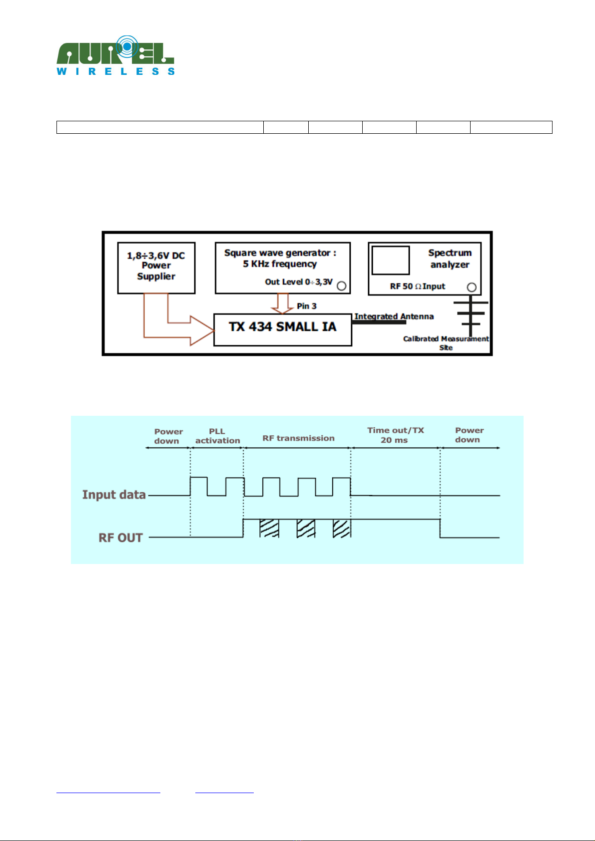
The declared technical features have been obtained by applying the following testing syste :
Picture : Testing syste
Device timing
Picture 2: Device ti ing
When TX DATA (pin.3) is connected to High level, the odule goes in IDLE ode, the consu ption is about
<1 a the PLL isn’t locked. The trans ission starts after 2 s fro rising-up level of TX DATA, that eans
first bits are not trans itted.
After 20 s fro the last transition fro high to low level of TX DATA, the odule goes to power-down
ode and the current supply is < 1µA.
Device usage
In order to obtain the perfor ances described in the technical specifications and to co ply with the
operating conditions, which characterize the Certification, the trans itter has to be ounted on a printed
circuit taking into account the following.
TX 434 SMALL IA
---------------------------------------------------------------------------------------------------------------------------------------------------
Instruction Manual
Technical features are subject to change without notice. AUR°EL S.p.A does not feel responsible for any da age caused by the device’s isuse.
-----------------------------------------------------------------------------------------------------------------------------
------------------------------------
----
AUREL S.p.A.
Via Foro dei Tigli, 4 - 47015 Modigliana (FC) – ITALY
Tel.: +39.0546.941124 Fax: +39.0546.941660
19/09/2018 - Rev.A
Pag 3 di 9
Power Supply:
1. TX 434 SMALL IA ust be supplied fro very low voltage safety source protected against the short
circuits. Maxi u voltage variations allowed: 1,8 ÷ 3,6 V. However it is preferable to aintain a stable
voltage to a predeter ined value in the range of voltage as specified above, using a "fast transient
response" voltage regulator.
2. Decoupling, close to the trans itter, with a cera ic capacitor of ini u 100nF.
3. Connect electrolytic capacitor 100uF, low ESR, close to pin 2 (+Vcc).
Input pin interface:
Put 100pF capacitor close to the corresponding input pin 3, connected between the and the ground plane.
Ground:
The ground ust surround at the best the welding area of the odule and ust also be realized in the
lower face of the PCB in order to obtain the opti al result, with the through holes connecting the two
ground planes.
Antenna:
E bedded Antenna, leave it free fro etal aterials. Keep at least a 2c radius free area.
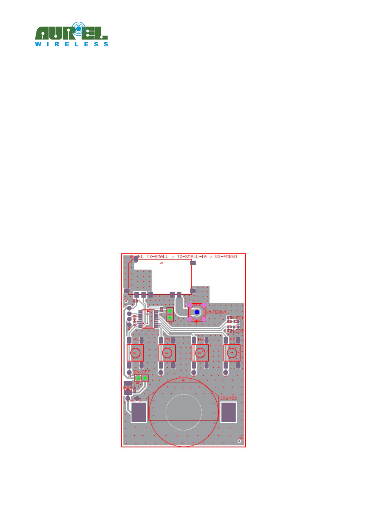
Picture 3: Mounting layout exa ple
TX 434 SMALL IA
---------------------------------------------------------------------------------------------------------------------------------------------------
Instruction Manual
Technical features are subject to change without notice. AUR°EL S.p.A does not feel responsible for any da age caused by the device’s isuse.
-----------------------------------------------------------------------------------------------------------------------------
------------------------------------
----
AUREL S.p.A.
Via Foro dei Tigli, 4 - 47015 Modigliana (FC) – ITALY
Tel.: +39.0546.941124 Fax: +39.0546.941660
19/09/2018 - Rev.A
Pag 4 di 9
Soldering and assembling layout SMD
Picture 4: Reco ended layout for Host board
In order to ensure the correct asse bly of the odule you are required to apply a production process
observing carefully the following reco endations:
Soldering paste: Use soldering paste as SAC305 (96,5% Sn, 3% Ag, 0,5% Cu), with a thickness> 150u .
Asse bly: the odule can be asse bled with auto atic achine by using a suction cup tool, applied on
bigger integrated circuit
Soldering: the odule can be soldered on host board, through a reflow profile for Lead-free co ponents.
Jedec standard “J-STD-020E”
Standard Jedec “J-STD-020E” defines te peratures and exposure ti es, is attached below graph and profile
table ti e / te perature reco ended for the purpose.
For host that provide ore reflow cycles it is reco ended to perfor the soldering of the odule at the
end of the soldering cycle, taking care to li it excessive vibrations during the ter inal phase of reflow
soldering paste.
P
rofile Feature
Pb
-
Free Assembly
Preheat/Soak
Temperature Min (T
smin
)
Temperature Max (T
smax
)
Time (t
s
) from (T
smin
to T
smax
)
150 °C
200 °C
60-140 seconds

TX 434 SMALL IA
---------------------------------------------------------------------------------------------------------------------------------------------------
Instruction Manual
Technical features are subject to change without notice. AUR°EL S.p.A does not feel responsible for any da age caused by the device’s isuse.
-----------------------------------------------------------------------------------------------------------------------------
------------------------------------
----
AUREL S.p.A.
Via Foro dei Tigli, 4 - 47015 Modigliana (FC) – ITALY
Tel.: +39.0546.941124 Fax: +39.0546.941660
19/09/2018 - Rev.A
Pag 5 di 9
Ramp-up rate (T
L
to T
p
) 2 °C/second max.
Liquidous temperature (T
L
)
Time (t
L
) maintained above T
L
217 °C
60-150 seconds
Peak package body temperature (T
p
) 245°
Time (t
p
)* within 5 °C of the specified classification
temperature (T
c
), see Figure 9.
30* seconds
Ramp-down rate (T
p
to T
L
) 6 °C/second max.
Time 25 °C to peak temperature 5 minutes max.
* Tolerance for peak profile temperature (T
p
) is defined as a supplier minimum and a user maximum.
Table : Detailed ti e / te peratures profile for soldering TX-434-SMALL-IA
Picture 5: Soldering profile for TX-434-SMALL-IA
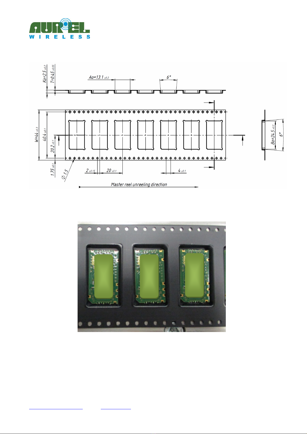
Specifications Packaging Tape and Reel
TX-434-SMALL-IA is packed in Tape and Reel co posed by an e bossed carrier tape and antistatic cover
tape.
In this way the odules are ESD protected and can be handled by achines for the auto atic asse bly of
SMD co ponents.
TX 434 SMALL IA
---------------------------------------------------------------------------------------------------------------------------------------------------
Instruction Manual
Technical features are subject to change without notice. AUR°EL S.p.A does not feel responsible for any da age caused by the device’s isuse.
-----------------------------------------------------------------------------------------------------------------------------
------------------------------------
----
AUREL S.p.A.
Via Foro dei Tigli, 4 - 47015 Modigliana (FC) – ITALY
Tel.: +39.0546.941124 Fax: +39.0546.941660
19/09/2018 - Rev.A
Pag 6 di 9
Picture 6: Tape and Reel drawing (in )
Picture 7: External aspect of the e bossed
TX 434 SMALL IA
---------------------------------------------------------------------------------------------------------------------------------------------------
Instruction Manual
Technical features are subject to change without notice. AUR°EL S.p.A does not feel responsible for any da age caused by the device’s isuse.
-----------------------------------------------------------------------------------------------------------------------------
------------------------------------
----
AUREL S.p.A.
Via Foro dei Tigli, 4 - 47015 Modigliana (FC) – ITALY
Tel.: +39.0546.941124 Fax: +39.0546.941660
19/09/2018 - Rev.A
Pag 7 di 9
Reference Rules
TX 434 SMALL IA trans itter is co pliant with the European set of rules EN 300 220-2, and EN 301 489-3.
The trans itter ust be supplied by a very low voltage safety source protected against short circuits.
The usage of the odule is foreseen inside enclosures that guarantee the EN 61000-4-2 nor ative not
directly applicable to the odule itself.
This device is co pliant with EN 62479, connected to the electro agnetic field hu an exposition, if used
with te poral duty cycle not higher than 10% like foreseen in CEPT 70-03 reco endation.
CEPT 70-03 Recommendation
TX 434 SMALL IA reco endation is referred to the 433.05 - 434.79 MHz har onized bandwidth and
therefore, in order to co ply with local regulations, the device ust be used on the ti e scale with
axi u duty-cycle ti e of 10% (equivalent to 6 inutes of usage on 60 inutes).
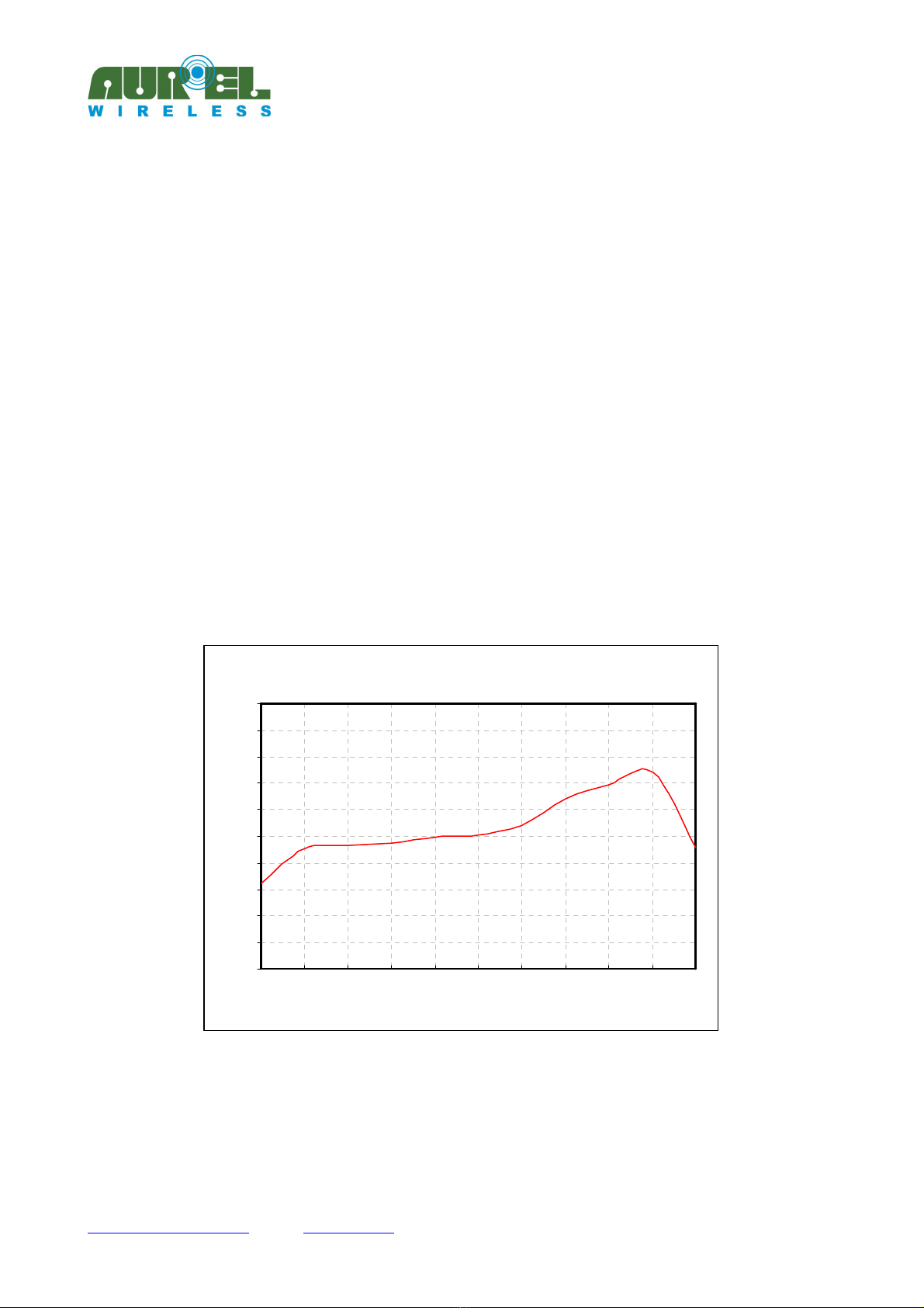
Reference curves
The ther al curves have been obtained by the testing syste shown in
Picture 1.
RF Power Delta - Temperature
-5
-4
-3
-2
-1
0
1
2
3
4
5
-20 -10 0 10 20 30 40 50 60 70 80
Temperature [°C]
RF Power Delta [dBm]
Picture 8: RF Power Delta Vs Te perature
TX 434 SMALL IA
---------------------------------------------------------------------------------------------------------------------------------------------------
Instruction Manual
Technical features are subject to change without notice. AUR°EL S.p.A does not feel responsible for any da age caused by the device’s isuse.
-----------------------------------------------------------------------------------------------------------------------------
------------------------------------
----
AUREL S.p.A.
Via Foro dei Tigli, 4 - 47015 Modigliana (FC) – ITALY
Tel.: +39.0546.941124 Fax: +39.0546.941660
19/09/2018 - Rev.A
Pag 8 di 9
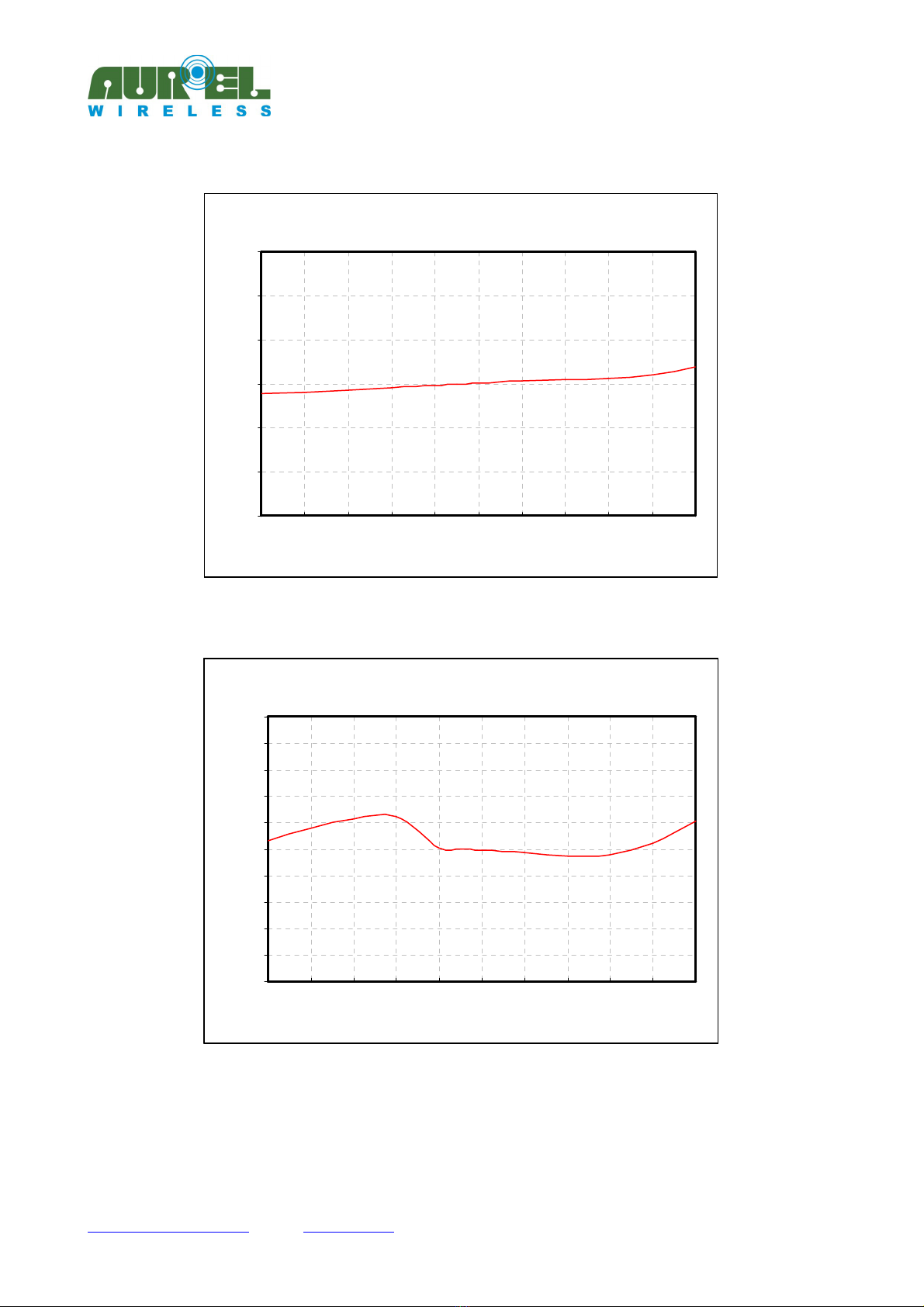
Absorbed current Delta - Temperature
-3
-2
-1
0
1
2
3
-20 -10 0 10 20 30 40 50 60 70 80
Temperature [°C]
Absorbed current Delta [mA]
Picture 9: Absorbed Current Delta Vs Te perature in TX-MODE
Frequency Delta - Temperature
-10
-8
-6
-4
-2
0
2
4
6
8
10
-20 -10 0 10 20 30 40 50 60 70 80
Temperature [°C]
Frequency Delta [KHz]
Picture 0: Delta Carrier frequency Vs Te perature

TX 434 SMALL IA
---------------------------------------------------------------------------------------------------------------------------------------------------
Instruction Manual
Technical features are subject to change without notice. AUR°EL S.p.A does not feel responsible for any da age caused by the device’s isuse.
-----------------------------------------------------------------------------------------------------------------------------
------------------------------------
----
AUREL S.p.A.
Via Foro dei Tigli, 4 - 47015 Modigliana (FC) – ITALY
Tel.: +39.0546.941124 Fax: +39.0546.941660
19/09/2018 - Rev.A
Pag 9 di 9
User manual revision summary
Release date
Revision user
manual Changes from the previous revision
19/09/2018 1.0 First Release
Table of contents
Other AUREL Transmitter manuals


