Nokeval 7100-RS485 User manual

1
No 271101
Manual
Programmable transmitter
7100-RS485
Nokeval

2
Programmable transmitter 7100 for RS485
General description:
Technical specification:
Thermocouples:
Sensor Range Linearity
E -100.... 900°C < 0.2°C -50.... 900°C
J -150.... 900°C < 0.2°C -50... 900°C
K -150.... 1350°C < 0.2°C -40... 400°C (<1°C > 400 °C)
L -100.... 900°C < 0.4°C -50... 900°C
T -150... 400°C < 0.2°C -150... 400°C
N 0....1300°C < 0.2°C 0.... 1300°C
R 0....1700°C < 0.3°C 400.... 1700°C (<1°C < 300 °C)
S 0....1700°C < 0.3°C 300.... 1700°C (<1°C < 300 °C)
C (W5) 0....2200°C < 0.3°C 400.... 2200°C (<0.4°C< 400 °C)
D (W3) 0....2200°C < 0.3°C 500.... 2200°C (<1°C < 500 °C)
B 400... 1700°C < 0.3°C 400.... 1700°C
G (W) 1000.. 2200°C < 0.4°C 1000...1700°C (<3 °C >1700 °C)
Range selection freely selectable
Calibration accuracy < 0.1 % of span
Cold junction compensation < 0.05 °C /°C
Sensor wire influence < 1kΩ, negligible
RTD's Pt100: Pt100 3- or 4-wire connections,
Other RTD's Pt500, Pt1000, Ni100, Ni1000
Range -200....+700 °C (Pt100, Pt250, Pt500)
-200....+200 °C (Pt1000)
0......+175 °C (Ni100, Ni1000)
Sensor current 0,3 mA
Calibration accuracy: 0.05% of span
Linearity < 0.03 °C (-200..700°C)
Sensor error correction freely offset selection (span)
Other RTD's 0-1000 Ω, Potentiometer 50-500 Ω
Potentiometer input:
range 3-wire connection 50-500 Ω
2-wire connection 2-wire 0-1000 Ω
mV inputs: -100...+100 mV
Accuracy 0,02% of span
Input impedance >10 MΩ
Linearity 0,01 % of span
Process inputs: 0..20 mA, 4..20 mA, -20..+20 mA
0..5 V, 0..10 V, -10...+10V
Input impedance Current: 5 Ωand voltage: 1 MΩ
Accuracy: 0.02 % of span
Linearity: 0.01 % of span
IR-sensors Exergen 140F-K (60°C) and 440F-K (220°C)
Range140F-K -40..+350°C (linearized range)
Range 440F-K -30..+600°C (linearized range)
Emissivity selectable by PC or hand held programmer
Programming by PC or
by hand held
programmer 6790
7100
Manufacturer:
Nokeval Oy,Yrittäjäkatu 12
FIN-37100 Nokia, FINLAND
Tel: +358 (0)3 3424800
Fax: +358 (0)3 3422066
Serial transmitter 7100 is exceptionally versatile and
accepts all common temperature and process signal
inputs. You can connect its digital output direct to devices
having RS485 serial port. The 32 transmitters may be
connected to one serial bus.
Transmitter suits for applications where digital input is
required, like PC serial port or programmable logic
controllers.
Nokeval serial converter 711 can execute RS485/RS232
conversions (two RS485 ports) if only RS232 port is
available. Serial transmitters are slightly more accurate
than transmitters with analog output because you do not
needto convert output tocurrentorvoltage output signal.
The linearity of A/D-converter is < 0.005 %, excluded
sensor error.
Power supply is isolated from input and output ( three-
wayisolation).
Typicalapplicationisdataaquisition for PC, f.ex.Nokeval
16-96 channel data collection software WinX (separate
data sheet available).
+
-
+
-
-DAC
Sensor:
TC
Pt100
mA
VProgrammer
Power supply
24 VDC
Serial output
RS-485
max. 32 transmitters
in same loop
A
B
6790

3
60
22.5 75 10
Removable terminals <1.5 mm²
Rail acc. to DIN 5002 (35mm)
Connection and dimensions:
Serial output:
Protocol Nokeval SCL
Baud rate 300, 1200, 2400, 4800, 9600,
19200 bps
Output RS485, 2-wire
max. distance 1000 m
Address 0-31
Configuration: serial data RS485 (terminal block)
or front panel connector by PC or
hand held programmer.
Programming socket:
Connection 2-pole Nokeval POL-connection
Serial data RS232, 1200 bps, 9600 bps
PC-connection 9-pole D-connector by PC's
serial port
Programmer hand held programmer 6790
General:
Power supply 24 VDC ±15%
Power consumption max. 40 mA
Temperature effects <0.003 %/°C
Galvanic isolation input/output 1000 VDC/ 1 min.
Measuring rate 4 samples/s.
AD-converter 16 bit
Operating temperature 0..60 °C
Ambient storage -20....+70 °C
Humidity (non -condensing) 0..95 %RH
Weight 80 g
Connection 1.5 mm2, AWG 16
Type 7100 - Pt100 - 0/600 - 9600
Model
Sensor input
Range
Baud rate
Example: 7100-Pt100-0/600, sensor: Pt100,
range 0..600 °C, baud rate 9600 bps
Transmitter is freely programmable but if you like it
factory configured use above mentioned marking
procedure.
How to order:
Optional:
Cable for transmitter/PC POL-RS232
Configuration software MekuWin
Hand held programmer 6790
7
-
8
10
9
Thermocouple,
mV-inputs and
IR-sensors
+
Socket for
POL-RS232 cable
-
5
7
6
4
3
2
1
-
8
10
9
RS-485 output
Pt100-sensor
3- or 4-wire*
Power supply
24 VDC
+
-
A
B
Com (option)
4-wire connection
(see page 7)
9
8
10
Potentiometer
3-wire connection
50-500 ohm
+
9
8
10
+
Potentiometer
2-wire connection
0-1000 ohm
-
5
7
6
-
8
10
9
mA- and
voltage inputs 0-5/10V
0/4-20 mA
+
+
-
(Com)

4
7100
Programming by PC
RS-232
cable
Programming
Transmitter programming is simple by menu based
configuration program MekuWin by PC or by hand held
programmer 6790, connected to transmitter front plug
socket Prog. Transmitter is connected to PC serial port
withserial signal cable POL-RS232.
ByMekuWin-configurationprogramyoumayselectsensor
typeandrange, input filtering andmax. conversion speed
of output. In addition, you can correct sensor errors by
shifting zero level or by changing input range. Program is
delivered on one diskette and it is installed by Setup-
program.
MekuWin is configuration program by which you can
configureseveralNokevaltransmitters(Meku-protocol).This
programdiffersfromconventialprogramsbecauseitdoes
not include setting commands, which are always loaded
from device to be configured. The big advantage of this
method is that you do not need to update the program
when you later add on new functions or new transmitter
models.Thesameconfigurationprogram suits for several
transmitters.
Configuration program MekuWIN
Sensor selections
Selection of outputs Quick selections:
Serial port selections
configuration windows
measurement display
contact disconnection.
Help window
assists in
selections and
tell which
settings can be
made and why.
Hardware requirement :
PC at least 486, 16Mb RAM
Operating system Windows 3.11,
Windows 95/98

5
Programming start:
Connect transmitter to PC serial port with adapter cable POL-
RS232. Do not forget to supply 24 V to the transmitter.
When you start MekuWin-program for the first time, selection
windowofcommunication settings appears automatically.Choose
in this window COM port and communication speed (BPS).
Use automatic Baud speed selection (Auto).
Set Preamble=0, Address and Slot=0. These functions are not
used in 7100 transmitter.
Main window has green quick menu (Quick) with four buttons (if
it is not visible, choose it in pull down menu Window/Quick).
The highest button opens common computer settings window
mentioned above. Second button (Conf) makes the contact with
target device. If communication fails, check computer settings,
connection of programming cable and power supply.
Sensor selections:
When connection with transmitter exists, display shows input
settings menu. Select sensor type in Sensor. Menu texts may
change according to selected sensor type.
After selections, settings are sent to transmitter by Send+Save
button.
Typical settings for K-type thermocouple
Input signal setting:
Sensor sensor type
Bip Bipolar measurement is possible by unscaled
inputs (mV, V and mA). Measuring range covers
also negative value, f.ex. ±100mA
4-wire 4-wire measurement is possible by inputs ohm, Pt
or Ni. You must select 4-wire measurement also
measuring card (jumper)
Lo Min. input value (process inputs). By unscaled
inputs function Lo acts as zero shift and can be
used to correct sensor error
Hi Max. input value (process inputs). By unscaled
inputs Hi acts as input multiplier by which you can
scaled input value
Emis emission or input coefficient, 1=not in use
R0 0°C resistance value of RTD (set Pt100=100 ohm)
Unit Celsius/Fahrenheit selection (to monitor display)
Filter digital filter, 1…0.001, 1=not in use
Slew limit limits the inputs slew rate. Defines how much the
new measurement result can differ from previous
one (measuring rate 4 times/second). This function
can be disabled by setting it on a larger value than
the measuring range or on the value 0 (default
value 0).
Pullup selection of sensor break down (ON/OFF)
Serial selection of serial signal address, transmitter baud
rate and decimal amount in the output signal.
Code Secret code for setting changes.Secret code
protects the transmitter against unwanted changes.
It is 6-digit numeral value. Default value is 000000
(not in use). If you happen to loose the secret code,
manufacturer will give you resetin structions for
new value.

6
Settings:
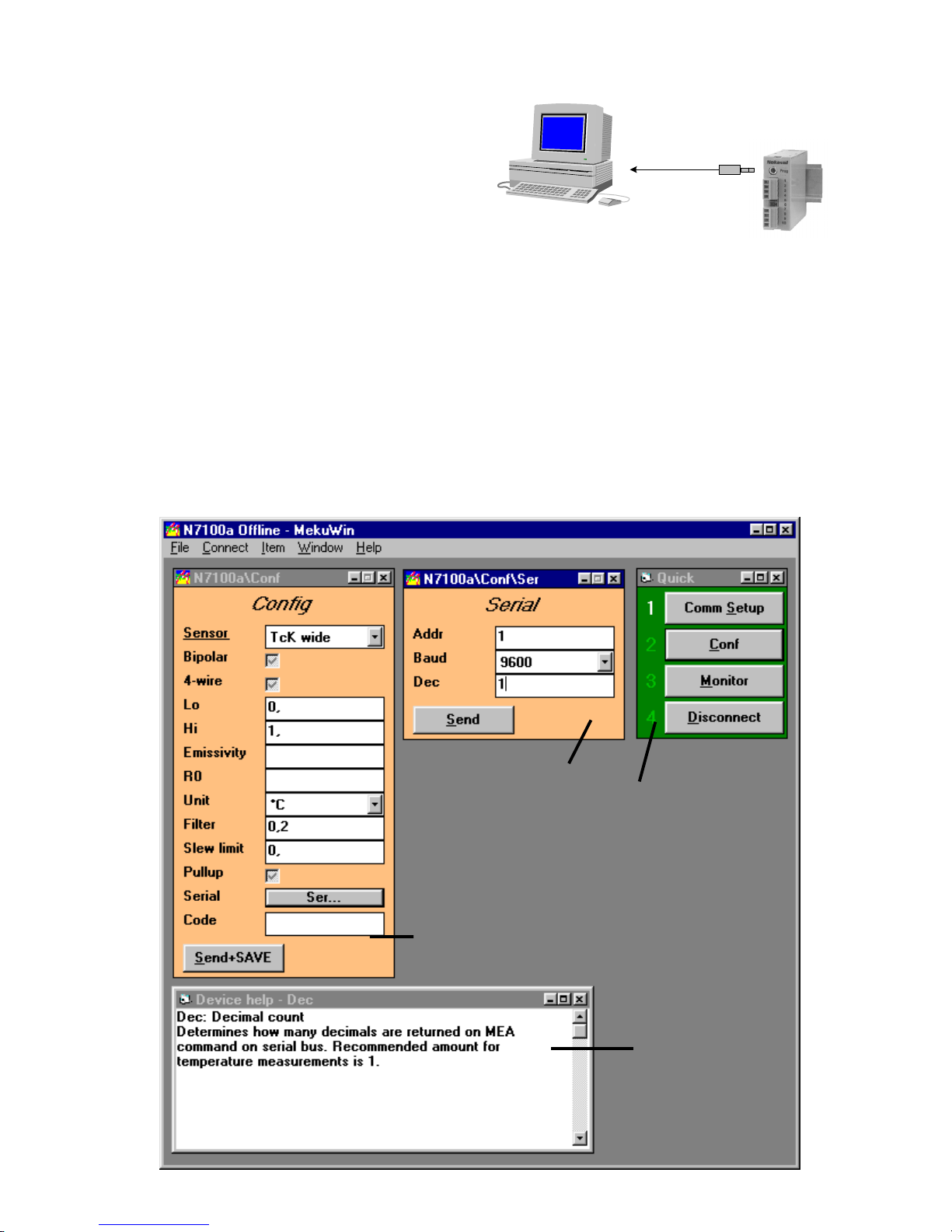
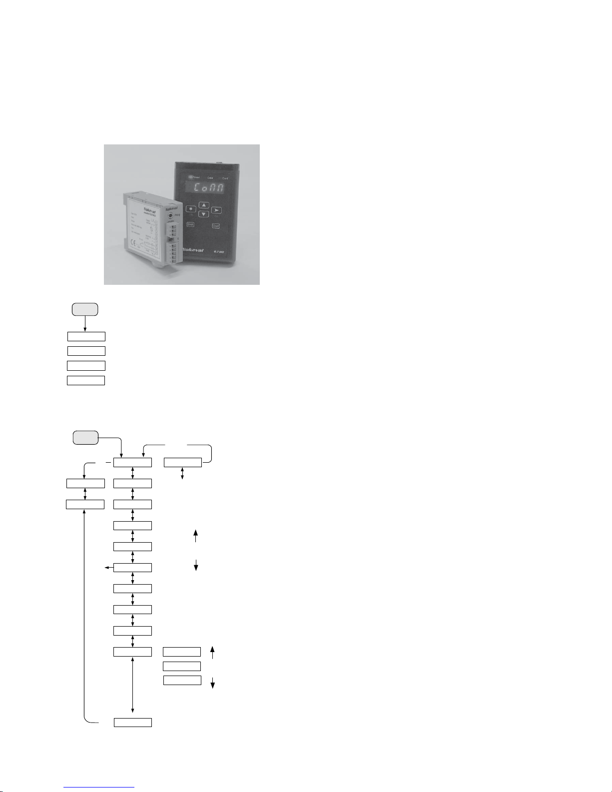
In configuration menu select input filtering and scaling of
output. Settings of input and output have
separatewindows(Input,Output).Inaddition,serialsignal
(Serial) has its own window which is needed only when
modem card is installed in transmitter (model 6725).
After sensor selection you may set various correcting
coefficients and filters.
When you install settings, notice whether your PC uses
commaorperiod.Erronousdecimal point is not accepted.
Thermocouple inputs TcB..TcT
Thermocoupletypesare marked shortly Tc+ sensor,f.ex.
TcB=B-type, TcK=K-type etc.. Type K has two ranges.
Narrow range TcKn (-80…+450) has better linearization.
Broader range TcK covers whole range
(-150..+1370 C). If sensor signal is too small or too big,
thevalue can becorrected byEmis-value. F.ex.you want
to correct sensor value at its max. reading by +2 %. Set
Emis-value 0.98. Default value is 1.
Correction of thermocouple sensor error
Thermocouplesarelinearizedtotemperature.Sometimes
youneed to correctsensorsignal.ByIR-thermopilesensor
this need depends on the emissivity of target device.
Emis-coefficient has following effect:
Differencebetweenmeasuredtemperaturevalueandcold
junction temperature is divided by Emis-value and the
result is added to coldjunction temperature. Finally Lo-
value is added. Emis is reverse value of slope and its
corner point is cold junction temperature or environment
temperature of transmitter.
Tcj = transmitter environment temperature (abt.)
Ts = Uncorrected sensor temperature measured by
transmitter
Tn = corrected temperature to display; true
temperature
6740 calculates Tn = (Ts-Tcj) / (Emis + Tcj + Lo).
The use of slope to correct sensor error (one point
correction): Set Emis = 1, Lo = 0.
Heat sensor to calibration temperature. Measure true
sensor temperature Tn and temperatureTs measured by
6740. Calculate: Emis = (Ts-Tcj) / (Tn-Tcj)
F.ex. true sensor temperature Tn = 27 °C. Temperature
measured by transmitter Ts = 895 °C. Set Correction
coefficient Emis = (895-27 °C) / (900-27) = 0.9942. At
hightemperaturescoldjunction temperature effectisvery
smallin Emis calculation. You may measurecold junction
temperature Tcj easily by connecting jumper to sensor
input.7100showsitscoldjunctiontemperatureatterminal
block.
Temperature measurement with RTD´s
Temperature sensors Pt100, Pt250, Pt1000 and Ni100
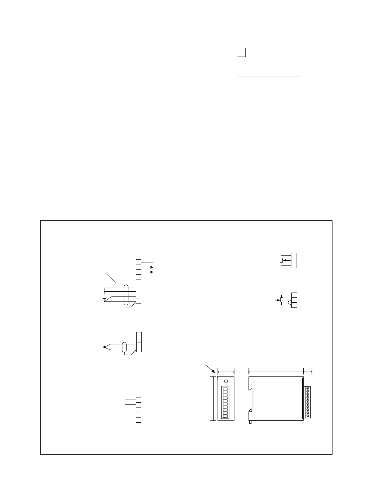
are available. Sensor connection 3- or 4-wire.
4-wiring requires jumper setting on circuit board, see
picture on page 7.
You can change sensor type by R0-value to
Pt100…Pt1000sensor only by givingresistance value in0
°C, f.ex. for Pt100 sensor R0 = 100.0 ohm or for pt250
sensor R0 = 250.0 ohm etc..
Calibration and error correction of RTD's
7100 assumes that sensor resistance in 0 °C is exactly
R0-setting. This means that 7100 compares sensor
resistance always with R0-setting. If 7100 shows too high
temperaturemeasuredbytheindividualsensor, thesensor
resistance is higher than nominal and you must increase
R0-value.
Advantage of this method is that also sensors can be
calibrated by giving the real measured resistance in 0 °C.
F.ex. if sensor resistance in 0 °C is 100.1 ohm, R0-value
will be 100.1 ohm.
Eliminating sensor tolerance may be done, if necessary,
also in other than 0 °C temperature. Because Platin
resistancesensors arenotfullylinear, you havetocalculate
R0-value according to equation below (other than 0 °C
temperaturecorrections)whenhighaccuracyisrequested.
R0 = valid R0-setting (f.ex. Pt100=100)
R0n = corrected R0-setting (equation below)
Ts = Uncorrected sensor temperature measured by
transmitter
Tn = corrected temperature to display; true
temperature
Kpt = Temp. coefficient of platin in RTD-table
corresponding temp. in question (abt. 0.385
ohm/°C)
Calculate new R0:
R0n = R0 * ( Ts * Kpt + 1 ) / (Tn * Kpt + 1)
F.ex. Sensor true temp. Tn = 100 °C and 7100 shows Ts =
99.7 °C, R0 = 100 (basic value).
Calculate correction R0n = 100 * ( 99.7 * 0.385 + 1 /
(100 * 0.385 + 1) = 99.71
Potentiometers
Potentiometer resistance value is 50…500 ohm by 3-wire
connectionand 0…1000 ohm by2-wire connection. When
potentiometer glide moves from one end to the other of
the potentiometer range , display value turns into Lo…Hi.
As you do not always use the whole potentiometer range,
thismustbenoticedinscaling.Theeasiestwayistoexploit
output scaling as follows: set in input window f.ex. Lo=0
and Hi=100. Drive potentiometer from beginning to end
and notice display values of 7100 (monitor). Set these
valuesinoutputwindow as Lo- and Hi-values of mA-output.
When performing variable resistance measurement
(0…1000ohm),thescalingisdonelikeinpointAbs.sensor
inputs.The sensor selection in menu = ohm.
0/4..20 mA and 0..5/10V process inputs
Inputranges: 0-5V,0-10V,0-20mA,4-20mA.When process
signalis selected,scaletheinput firstdirectlyasengineering
units on monitor display. Set min. (Lo) and max. (Hi)
corresponding value, f.ex. input 0-10V corresponds in
display range 200-500. Set Lo=200 and Hi=500 (output
range is set in its own window). In case of V-input, the
jumperof the measuringcard mustbe in position1-2 (mV-
inputs do not need jumper setting).

7
Abs. inputs V, ±10 V, 20 mA and ohm
The abs. inputs as not scale in the same way as process
inputs simply by giving wanted display values to monitor-
display.Inabs.inputsHi-setting actsascoefficienttowhich
Lo-value is added. If input starts from zero set Lo = 0 V
(Ma,ohm),inputismultiplied in this case only byHi-value.
You may select bipolar input by making cross to square
(Bip) in menu. If you do not need bipolar input, select
always unipolar input because then max. resolution of A/
D-conversion (1/64000) is available.
mV-inputs
mVinputsmaybeuni-orbipolaronrange+-100mV(Bip).
Unipolarrangeis more accurate becausemax. resolution
of A/D-conversion (1/64000) is available. Selection
Bip=Bipolar.
Infrared-sensors
Noncontacting IR-sensor ranges arelinearized onwhole
measuring range for sensor types Exergen 140F-K
(-40..+350°C) and 440F-K (-30..+600°C). Emission
coefficient corrects measured value to show true
temperature according to emissivity of target object.
Exergen sensors are calibrated for emission coefficient
0.9(grey body).Ifobjectemision coefficientis 0.7setEmis-
value 0.7/0.9 = 0.77.
More details in point Thermocouple and IR-sensor
correcting coefficients (experimental Emis-control).
Other settings
Bip: Bipolarmeasuremen is possibleby unscaledinputs
(mV, V and mA). Measuring range covers also negative
value, f.ex. ±100mA.
4-wire: 4-wire measurement is posible by inputs ohm, Pt
or Ni. You must select 4-wire measurement also
measuring card (jumper).
Lo: Min. input value (process inputs, f.ex. 4mA). By
unscaled inputs function Lo acts as zero shift and can be
usedtocorrect sensor error.Value isgiven in engineering
unit f.ex. -5 °C. Zero shift is added first eventually set Hi-
coefficient.
Hi: Max. input value (process inputs, f.ex. 20mA). By
unscaled inputs Hi acts as input multiplier by which you
can scale input value.
Emis: Emission or input multiplier, 1 = multiplier 1
R0:RTD's0°Cresistancevalue(f.ex.setPt100=100ohm)
Unit: C/Fselection only withtemperature sensors (Tc/Pt/
Ni).
Filt: filter
Notinuse=1.000.Normalfiltering0.200means(1/0.2=5)
thatthelatestmeasurementincludesonenewandfourold
measurements. Diminishing the filter value increases the
damping effect. Filtering behaves like RC-circuit.
Slew: slew rate
Onemeasurementcannotchangemeasuringresultmore
than slew-value allows.
It can be used to eliminate interference peaks. One
measurement lasts abt.0.25 second so if slew value is 1,
themeasuringresult can raise 4 unitsin one second (f.ex.
4C/s). If you prefer not to to use this limiter, set value
larger than measuring range or value 0.
Pullup: sensor break pullup
If pullup is set on, a weak current is fed from time to time
to sensor line in order to find out eventual sensor breaks.
Function does not work with process signals (V, mA). In
these signals internal pulldown leads input to 0 V or to 0
mA.
Pullupis not recommended withhigh impedance sensors
(f.ex.Exergen)becausethefeedingof intermittent current
to sensor line disturbs measuring (capacitive charge). By
RTD´s pullup is useful for wire breaks; sensor break is
alwaysdetected.
Serial: Youcanset transmitter address, transmitter baud
rate (300, 1200, 2400, 4800, 9600 or 19200) and output
signal decimal settings.
Code: secret code for setting changes
Secret code protects the transmitter against unwanted
changes. It is 6-digit numeral value. Default value is
000000 (not in use). If you happen to loose the secret
code,the manufacturer willgive you resetinstructions for
new setting.
3 2 1
Jumper selections of input card Voltage input 0-10V:
Jumper selection 1-2
(Factory setting)
4-wire RTD-sensors:
Jumper selection 2-3
4-wire connection of voltage input (10V)
and of resistance measurement on
measuring card
Unusual sensor inputs require jumper selection on
measuring card. Open the right hand cover of the
transmitter. You can easily remove measuring card from
basic board. Select jumper position according to picture
below.
Last unit termination and fixed baud rate
selection
By serial signal RS485 last unit must be terminated by
connectin jumper J1 (110 ohm resistor).
If you don't know transmitters baud rate, you can set for
unit's fixed baud rate 9600 bps for jumper J2.
Input card
J1
J2
Jumper selections of mother board

8
Thermocouples
RTD's Pt100
711
RS485/RS232
RS-Converter
Process input
RS485 max. 1000 m
Serial communication
Baudrate:300,1200,2400,4800, 9600and19200
1 Start, 8 Data and 1 Stop bit, no parity.
Serial protocol (SCL):
MESSAGES: When asking the measurement data from
the transmitter 7100 through the serial port, a command
sequencewhichis in accordance withthe SCL protocolis
usedfor the inquiry:
<ADDR+80h>COMMANDSTRING<ETX><BCC>
<ADDR>
The first byte character to be sent contains the ADDR
(0..127)oftheaddressofthedestinationdeviceandatthe
same time functions as the start bit of the command. 80H
(in a decimal 128) with which an uppermost bit is set as
the number one is added to the address.
COMMAND STRING: When measurement data is re-
quested,the actual command is:MEA CH1 ?, in which1
means the channel number. (there is only one channel in
the transmitter 7100 so the number is always 1).
<ETX>
<ETX>meantheendmarkofthe command,
ASCIIcharacter03h.
<BCC>
Finally the checksum is calculated using the XOR opera-
tiononthebytecharactersoftheactualcommandincluding
the ETX. In the example the ASCII codes have been
presentedinhexadecimal.
e.g.
One wants the measurement result from the display unit
address 1. An inquiry is sent:
MEA CH 1 ?(ASCIIcodesshownfor<BCC>calculation)
M E A C H 1 ?<ETX> <BCC>
4Dx45x41x20x43x48x20x31x20x3F x03 = 6F
(XORoperationpresentedwithacharacterx)(ASCIIcode
20hcorrespondstospacecharacter)
So the following bytes are sent to 7100:
81 4D 45 41 20 43 48 20 31 20 3F 03 6F
RETURN MESSAGE: The answer from the transmitter
7100 isobtained in the followingformat:
<ACK>RETURNMESSAGE<ETX><BCC>
<ACK>
Thefirstbyteoftheanswercontainsthestartoftheanswer
<ACK>(ASCII-code06h).
RETURN MESSAGE: The latest measurement result is
represented in ASCII form, e.g. 21.3. It is constructed of
characters0..9,-andperrod.Thelengthisdependableon
thereadingandtheamountofdigitsafterthedecimalpoint
selected.
Whenthetransmitterhasdetectedasensororwirebreak,
it will respond with message 100001..100003 instead,
dependingonthefault.IfPULLUPsettinginconfiguration
isdisabled, the transmitter willnever give thisresponse.
<BCC>
ThetransmittercalculatesthechecksumusingXORopera-
tiononallthebytesoftheresponse,including<ACK>and
<ETX>.
e.g.
e.g.Whenameasurementresultisforexample21.3,itwill
beobtainedfromthepanelmeterinthefollowingform
<ACK> 2 1 . 3 <ETX> <BCC>
Answer: 06 32 31 2E 33 03 1B

9
Hand held programmer 6790
You can easily program transmitters with hand held
programmer which is particularly useful in field
conditions. Menu structure is similar to PC-program.
Programmer is simply connected to transmitters plug
socket Prog with cable. Programmer is universal and
does not include configuration program which is loaded
from transmitter to be configured.
The use of programmer
When you have swicthed on 6790, display shows text
Conn. Set first serial communication baud rate 9600
(Baud) and then Slot setting value 0 (default value).
Address is not needed.
Switch on power supply 24 V and connect cable to
transmitter plug socket Prog. Now you can start loading
of configuration program from transmitter by pushing ➤
button. Loading takes a few seconds. If sensor is
connected to transmitter, display shows sensor
measuring value. An open input may show random
values.
Start programming by pushing Conf-button until the
menu shows text Sensor. If you like to change sensor
push ➤button and make changes by ▲ ▼ buttons.
After selection come back to main level by
❉-button.
Settings are sent or canceled in Save or Undo stage by
➤ button.
Input settings:
Sensor Selection of sensor type.
Bip Bipolar measurement is possible by unscaled inputs
Measuring range covers also negative value.
4-wire ohm-, Pt ja Ni-sensor 4-wire connection
Lo Zero shift (sensor calibration if necessary).
Hi Scaling of input (only mA- and V-inputs).
R0 RTD's 0 °C resistance value (set Pt100=100 ohm).
Emis Emission or input coefficient, 1 = not in use.
Unit Selection of Celsius/Fahrenheit (monitor näytölle).
Filter Digital filter, 1...0.001, 1 = not in use.
Slew limit Limiter of slew rate. One measurement can not change
measuringresult more than slew-valueallows(measuringrate
is 4 times/second). If you do not want to use it, set value 0 or
larger than measuring range.
Pullup Selection of sensor break sensing (ON/OFF).
Serial Serial signal settings:
Addr Transmitter address selection: 0..99
Baud Transmitter baud rate selection: 300, 1200, 2400, 4800,
9600 or 19200.
Dec Selection of decimal amount
Code Setting of secret code. You can not change settings without
secret code if it is set to other than default value 000000.
Save Exit programming stage by ★button and save
settings to transmitter by ➤➤
➤➤
➤button.
Undo Cancel settings and exit without saving by ➤➤
➤➤
➤button.
Settings are described in more details on pages 6 and 8.
Lo
Hi
Ro
Emis
Unit
*
Filter
Slew
Pullup
Serial
Sensor
Code
Addr
Baud
Dec
Save
Undo
*
*
Slot
Conn
➤
Baud
Address
Conf
▼▲
▼▲
➤
➤
➤
➤
➤
➤
➤
➤
➤
➤
➤
You can
move on or
change
numbers and
values in
programming
menu
Pt100
Load configuration program
from transmitter
*
Select sensors
Start programming by pushing
Conf -button
On
Start
Set programmer
baud rate
Set value 0
No in use

10
Notes:

11
Notes:

12
Yrittäjäkatu 12
37100 NOKIA
Tel. +358 (0)3-342 4800
http:// www.nokeval.com
Nokeval Oy
Manufacturer:
This manual suits for next models
1
Table of contents
Other Nokeval Transmitter manuals