AURES TEOSWIDE 22i5 User manual

TEOSWIDE 22i3 & 22i5
User Manual

Copyright Notice:
No part of this documentation may be reproduced, transcribed, transmitted, or translated in any language, in any form or by any means, except duplication
of documentation by the purchaser for backup purpose, without written consent of AURES Technologies.
Products and corporate names appearing in this documentation may or may not be registered trademarks or copyrights of their respective companies, and
are used only for identication or explanation and to the owners’ benet, without intent to infringe.
Disclaimer:
Specifications and information contained in this documentation are furnished for informational use only and subject to change without notice, and should not
be constructed as a commitment by AURES. AURES assumes no responsibility for any errors or omissions that may appear in this documentation.
With respect to the contents of this documentation, AURES does not provide warranty of any kind, either expressed or implied, including but not limited to
the implied warranties or conditions of merchantability or fitness for a particular purpose.
In no event shall AURES, its directors, officers, employees, or agents be liable for any indirect, special, incidental, or consequential damages (including
damages for loss of profits, loss of business, loss of data, interruption of business and the like), even if AURES has been advised of the possibility of such
damages arising from any defect or error in the documentation or product.
The terms HDMI™ and HDMI High-Denition Multimedia Interface, and the HDMI logo are trademarks or registered trademarks of HDMI Licensing LLC in
the United States and other countries.

Table of Contents
Chapter 1: General Information
1.1 Introduction & Features 4
1.2 General Specication 5
1.3 LCD Specication 5
1.4 Environmental Specications 6
1.5 Power Supply Specications 6
1.6 I/O Drawing & Pin Denition 7-8
1.7 Dimension Drawing 9
Chapter 2: How to Guides
2.1 How to Set up Install Windows 7 OS 10-11
2.2 How to Set Up System Drivers 12-13
2.3 How to Access Storage Device 14
2.4 How to Use the OSD Controls 15
Appendix
A.1 Troubleshooting 16
Chapter 1: General Information
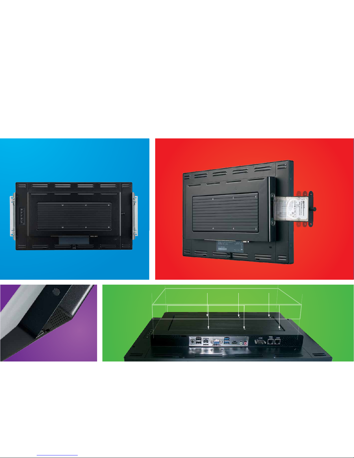
1.1 Introduction & Features
Built in
speakers
Vesa 100x100 mount
Side bracket
HDD or SSD
can be easily
accessed for
maintenance
Model TEOSWIDE 22i3 / TEOSWIDE 22i5
Processor Intel® Haswell i3-4010U 1.7GHz, Cach 3M / Intel® Haswell i5-4300U 1.9GHz to 2.9GHz
System Memory 2 GB Standard, Maximum 8G (DDR3L)
Power Supply 84W
Storage Device 1 x 2.5” SATA HDD or SSD
Speaker 1W Speaker / 2 Channel
Housing Color Black
Construction Sheet Metal, Glass, ABS
LCD Display 21.5” TFT Active Matrix Panel
Display Size 476.64 (H) x 268.11 (V) mm
Pixel Pitch 0.24825 (H) x 0.24825 (V) mm
Display Mode
SVGA 800 x 600 (60 Hz)
SVGA 800 x 600 (72 Hz)
SVGA 800 x 600 (75 Hz)
XGA 1024 x 768 (60 Hz)
XGA 1024 x 768 (70 Hz)
XGA 1024 x 768 (75 Hz)
XGA 1152 x 864 (60 Hz)
SXGA 1280 x 1024 (60 Hz)
SXGA 1280 x 1024 (75 Hz)
WXGA 1280 x 800 (60 Hz)
WXGA 1280 x 768 (60 Hz)
WXGA 1440 x 900 (60 Hz)
WXGA 1600 x 900 (60 Hz)
WXGA 1600 x 900 (75 Hz)
WXGA 1680 x 1050 (60 Hz)
HD 1280 x 720 (60 Hz)
HD 1920 x 1080 (60 Hz)
Native FHD 1920 x 1080 (60 Hz)
Non-touch 250 cd/m2 (Typical)
Projected Capacitive Touch 225 cd/m2 (Typical)
Response Time Tr= 5 msec (Typical)
Display Color 16.7 million
Viewing Angle (L/R)= -85°/+85° (typical), (U/D) -80°/+80° (Typical)
Plug & Play DDC 2B
1.2 Specication
1.3 LCD Information

1.4 Environmental Specication
Temperature Ranges
Operating Temperature (Independent of altitude) 0°C to 40°C
Non-Operating Temperature (Independent of altitude) -20° C to 60°C
Humidity
Operating (non-condensing) 20% to 80%
Non-Operating (38.7C maximum wet bulb temperature) 10% to 90%
Altitude Ranges
Operating 0 to + 2000 m
Non-Operating 0 to + 12192 m
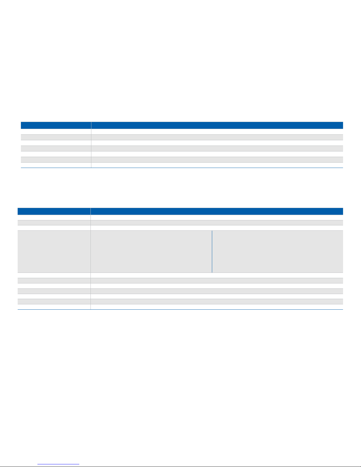
1.5 Power Supply Specication
Input voltage 100 to 240 V~
Input frequency 50/60 Hz
Output voltage 12 V
Output line and load regulation +/- 5%
Output current 7 Amps Rated
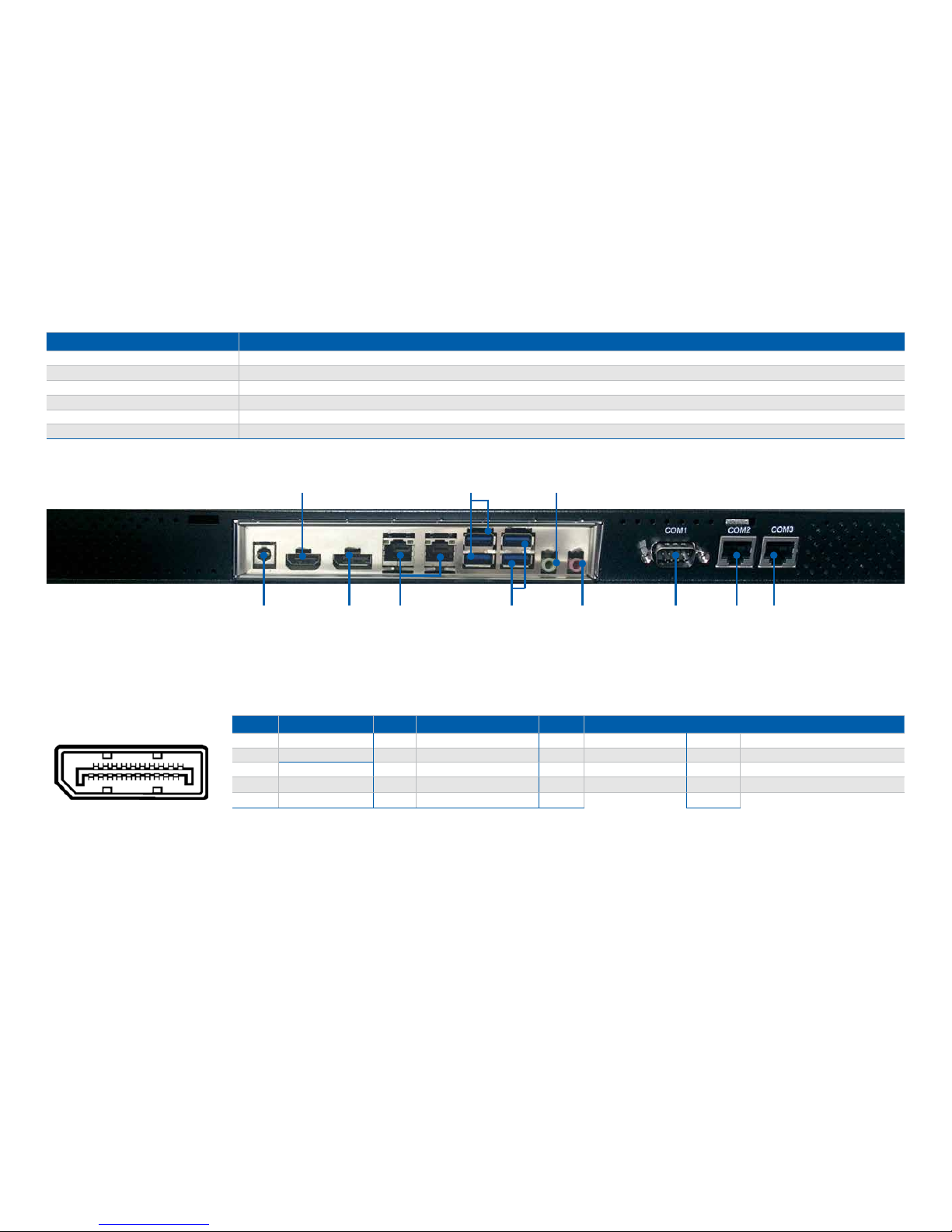
Serial Port 3 External: COM1 (DB9); COM2, COM3 (RJ-232/422/485)
USB USB 3.0 x 2; USB 2.0 x 2
Ethernet LAN x 1
Video DP x 1; HDMI x 1
Audio Line out x 1; Mic x 1
DC output DC Jack 12V x 1
1.6 I/O Interface & Pin Denition
RS-232/422/485 x 2DP x 1 LAN x 2DC-in x 1 DB9 x 1Mic x 1
Line out x 1USB 3.0 x 2HDMI x 1
USB 3.0 x 2 x 1
PIN DESC PIN DESC PIN DESC PN
1Main Link Lane 0+ 6Main Link Lane1- 11 GND 16 GND
2GND 7Main Link Lane2+ 12 Main Link Lane3- 17 Auxiliary Channel-
3Main Link Lane0- 8GND 13 Conguration 1 18 Hot Plug Delect
4Main Link Lane1+ 9Main Link Lane2- 14 Conguration 1
5GND 10 Main Link Lane3+ 15 Auxiliary Channel+
Display Port
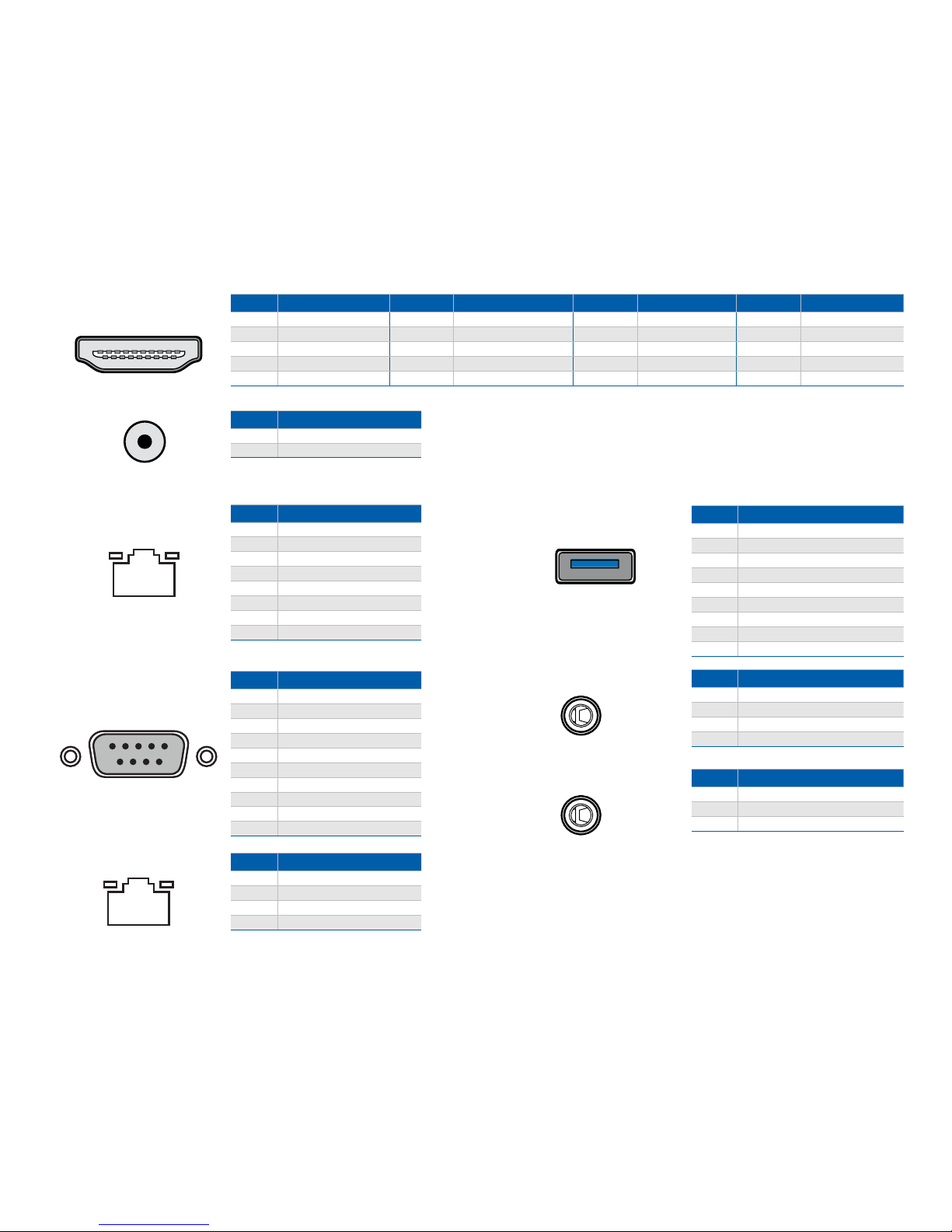
PIN DESC PIN DESC PIN DESC PIN DESC
1TMDS Data2+ 6TMDS Data1− 11 TMDS Clock Shield 16 DDC data
2TMDS Data2 Shield 7TMDS Data0+ 12 TMDS Clock− 17 Ground
3TMDS Data2− 8TMDS Data0 Shield 13 CEC 18 +5 V
4TMDS Data1+ 9TMDS Data0− 14 NC 19 Hot Plug detect
5TMDS Data1 Shield 10 TMDS Clock+ 15 DDC clock
PIN DESC
1 DC in (12V only)
2GND
PIN DESC
1 RI-
2 CTS-
3 GND
4RTS-
5DTR-
6DSR-
7 TX
8RX
DC-IN
COM RS-232
COM RS-232 PIN DESC
SHELL GND
1 DCD, Data carrier detect
2 RXD, Receive data
3TXD, Transmit data
4DTR, Data set ready
5GND, ground
6DSR, Data set ready
7RTS, Request to send
8CTS, Clear to send
9RI, Ring indicator
USB 3.0 PIN DESC
1 VBUS
2-Data
3+Data
4GND
5StdA_SSRX-
6StdA_SSRX+
7GND_DRAIN
8 StdA_SSTX-
9StdA_SSTX+
LINE OUT PIN DESC
1 Left Channel
2 Right Channel
3 +Data
4GND
MIC PIN DESC
1 MIC_L
2 MIC_R
3 GND
PIN DESC
1 TD+
2TD-
3 RD+
6RD-
LAN
HDMI™
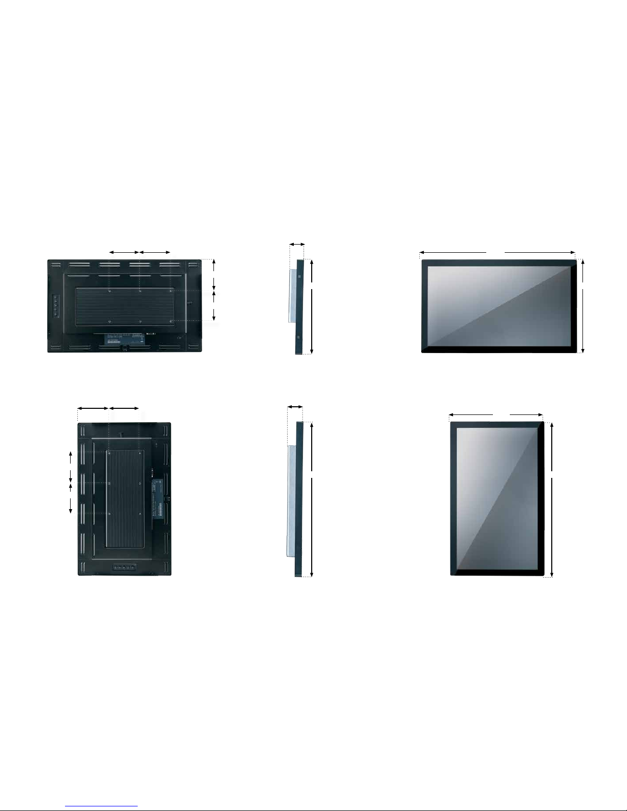
1.7 Dimensions
517.4
517.4
313.3
517.4
313.3
55.1
55.1
313.3
106.7
100.0
100.0100.0
106.7 100.0
100.0
100.0
Chapter 2: How to Guides
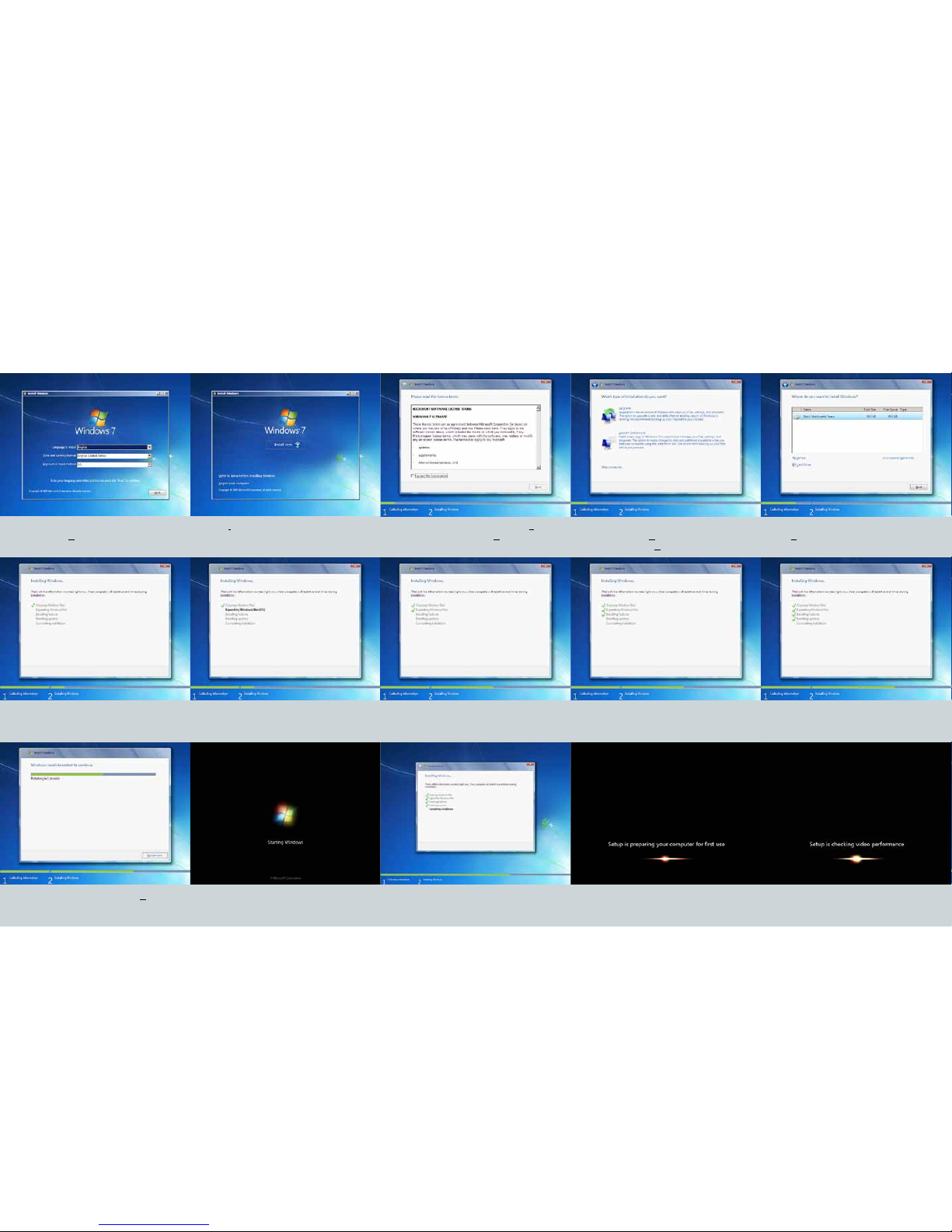
2. Click Install now
3. Read license terms, click the box “I accept
the license terms” then click Next
4. If you are upgrading from a older version of
Windows, choose Upgrade. If this is a new OS
installation, choose Custom.
5. Choose the disk to install Windows then
click Next
5. During the Windows installation process, the system will shut down and restart multiple times.
6. When you see this screen, click Restart now 7. System will do an automatic system restart
1. Select language, time and keyboard set-
tings then click Next. This entire process will
take roughly 30 minutes.
2.1 How to set up Windows 7 Industrial Operating System
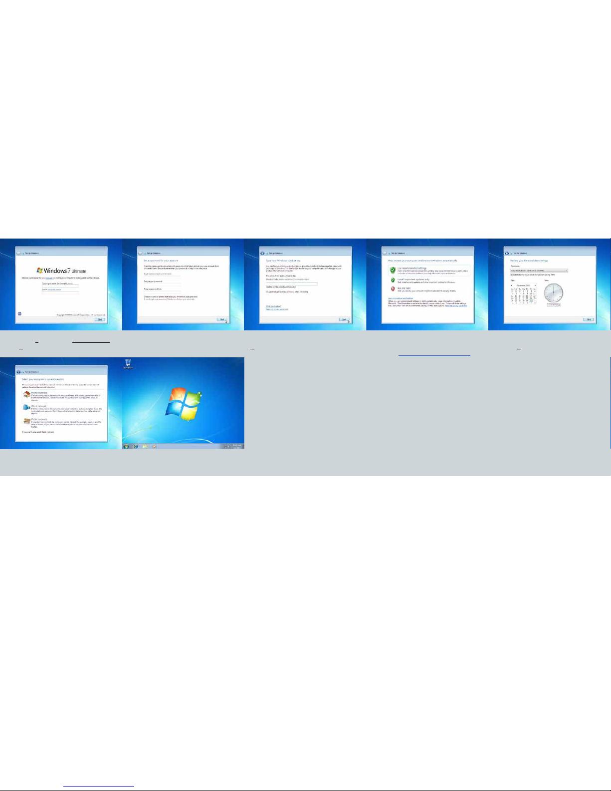
8. Create a user name and computer name then
click Next
9. Create your password and hint (optional) 10. Type in your Windows product key then click
Next
11. Choose any option depending on your
needs. Find out more by cchoosing the blue
underlined Learn more about each option
12. Choose the correct time zone and date
then click Next
13. Choose your network type 14. Congratulations, Windows 7 operating sys-
tem has been set up
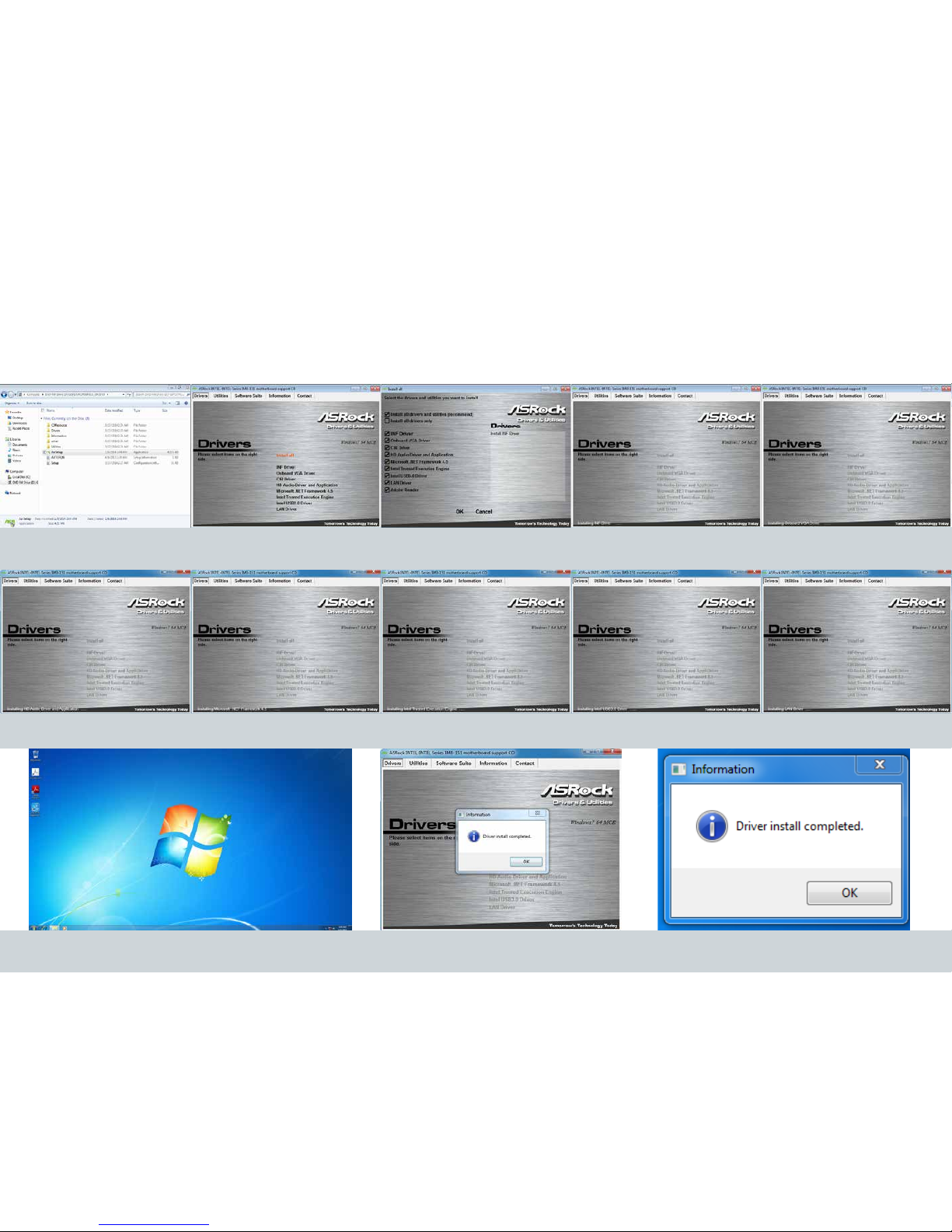
1. Choose the le folder for drivers and
choose AsrSetup
2. Select install all then click OK 3. During the installation process, the system will automatically restart. Do not force shut down or run additional programs during this process.
2.2 How to set up System Drivers
Reference Images
4. If Adobe Reader was checked on Step 3, then at this point it will be installed. 5. Click OK. Congratulations the driver installation is complete
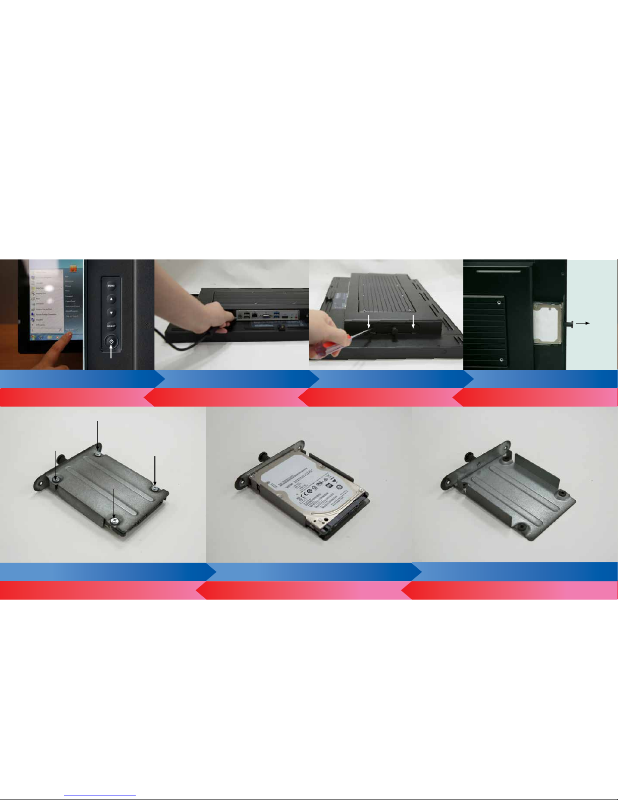
2.3 How to Install and Access Storage Device
1. Shut down the system (left) 2. Unplug the power adaptor 3. Remove the two screws 4. Pull out your storage device holder
5. Remove the 4 screw on the back side of the storage device 6. Remove the storage device Complete
3. Turn the holder around and tighten the screws in the indicated area 2. Add the storage device on the holder 1. If storage device was not puchased through TES, the holder will be found
in accessory box
7. Start up the system by pressing the power icon
(right)
6.Plug in the power adaptor 5. Screw in the two screws 4. Push in your storage device holder
BLUE: IF SYSTEM IS ALREADY ON AND YOU NEED TO MAINTAIN STORAGE DEVICE
RED: NEW HDD INSTALL (START FROM BOTTOM RIGHT)

2.4 How to Set Up Side Bracket
1. There are 4 locations where you can install the side bracket. The location
in which you should choose to install the side bracket should be determined
by the design of your nal assembly. We suggest using the sides of the
bracket (side is determined by if nal assembly is portrait or landscape.
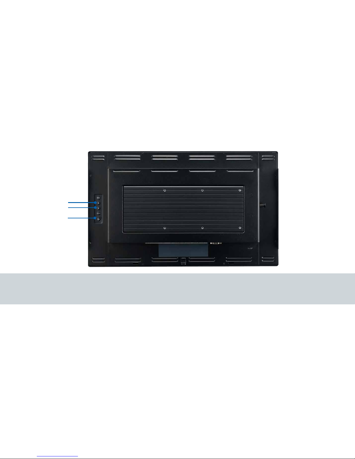
1. Press the “Power” button to on/off computer system
2. Adjust the value of the adjustment items by pressing the “Up” or “Down” button.
3. Menu and Select no function
2.4 How to Use OSD Controls
Power
Increase Value
Decrease Value

Touch and LCD Panel Related
No image appears on screen.
Check that all the I/O and power connectors are correctly and well connected described in the “Installation” section.
Make sure the pins of the connectors are not crooked or broken.
Partial Image or incorrectly displayed image.
Check to see if the resolution of your computer is higher than that of the LCD display.
Recongure the resolution of your computer to make it less than or equal to 1920 x 1080.
Touch no function (for windows 7 only)
When P-CAP touch monitor turn the power on or o in the time.
Please wait~15 seconds for the touch function to be normal.
Other
COM ports are not functioning properly
Check if the I/O ports are enabled in the CMOS setup.
Check if there are any IRQ conicts.
e M/B or I/O cable could be defective.
LAN Is Not Functioning Properly
Check if the LAN driver is installed properly.
Check if the RJ45 cable is properly connected.
e on-board LAN chip could be defective.
Cannot Detect SATA Storage HDD/SSD
Make sure storage device is well connected in the Sata Drive Bay.
HDD power cable is not connected properly to the main board or it could be defective.
Check CMOS setup, set SATA HDD to Auto Detect.
On-board SATA port could be defective.
Conrm HDD setup in BIOS is normal
Chapter 3: Appendix
Troubleshooting
This manual suits for next models
1
Table of contents
Other AURES Touch Panel manuals


