Aurora Audio Stinger User manual

AURORA AUDIO INTERNATIONAL
1518 North Cahuenga Boulevard
Hollywood, CA 90028
Phone: 323 4 2 13 Fax: 323 4 2 137
Email: [email protected]
Website: www.auroraaudio.net
Aurora Audio Stinger Microphone and Instrument Amplifier
Page Index -
Page 2 – Introduction
Page 3 – Power Supply information
Page 4 – Aurora Stinger Block Diagram
Page 5 – Connecting To The Aurora Stinger
Page 6 – The Regular DI/Mic input and Correct Gain Structure
Page 7 – The Instrument input DI and EQ controls
Page 8 – Equalizer, Phase, and Phantom Power Controls
Page 9 – Using the Aurora Stinger
Page 10 – International dBFS Levels
Page 11– Specifications
Page 12 – Warranty details
1

Introduction -
“Congratulations on your purchase of our Stinger! I am confident that you
will find that its many features and great Class A discrete vintage sound will
help you to make great recordings.
The Aurora Stinger is a portable and professional piece of equipment.
Read through this manual to familiarize yourself with the controls and
optimal operating procedures.
Please familiarize yourself with the sections dealing with metering and gain
structure when recording to digital equipment.”
-Geoff Tanner
2

Power Supply information -
The Aurora Stinger has internal regulated power supplies that automatically
adjust to whatever a.c. power source you connect it to. There is no voltage
selection switch as the power supplies will automatically work between 80
and 2 5 volts a.c 50 or 0Hz.
The unit must be grounded using the supplied 3 core, 3 pin connector cable.
Do not use with any ground lifting adapter or two pin extension cable.
For the best noise performance and maximum safety, always ensure that the
Stinger is plugged into a 3 pin grounded power outlet.
3
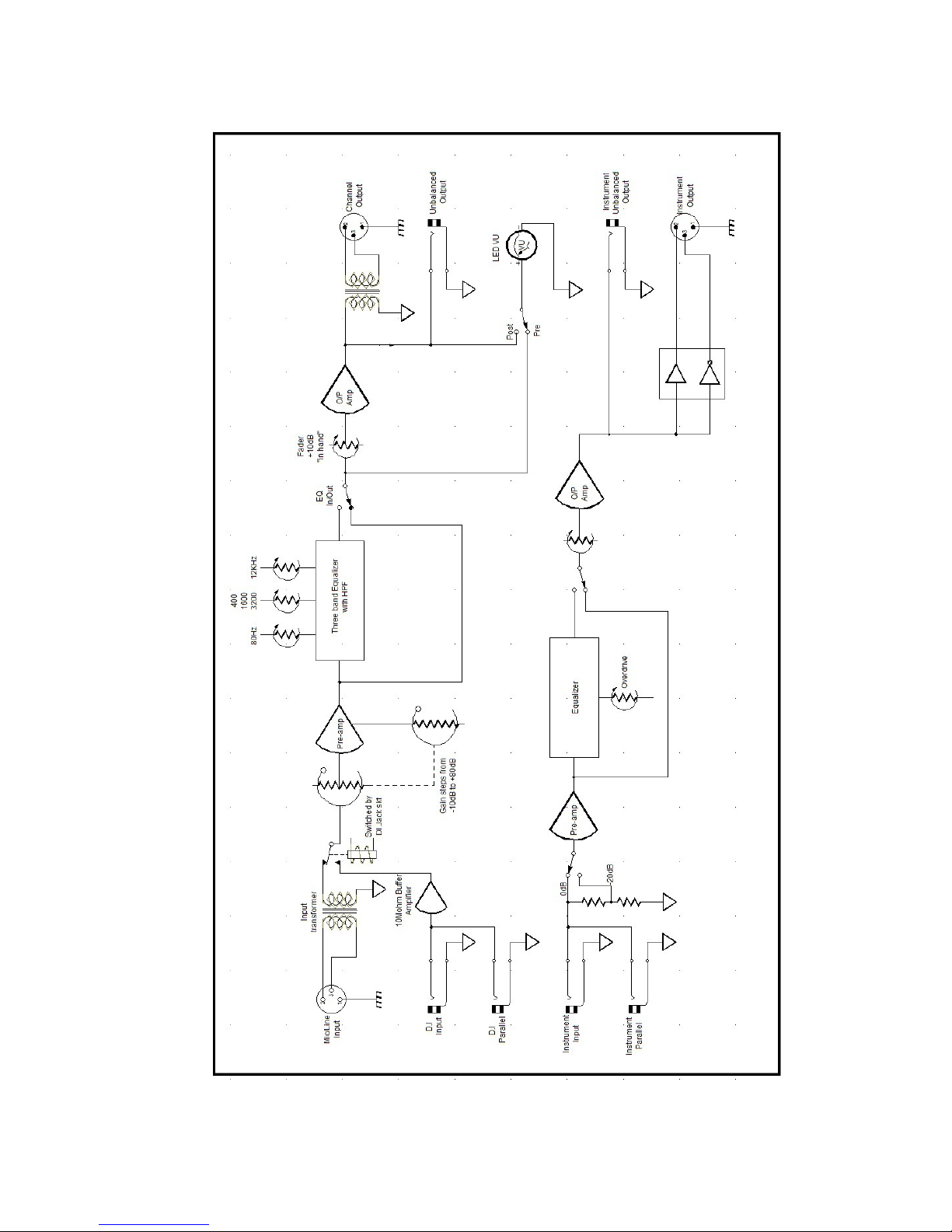
Block Diagram -
4
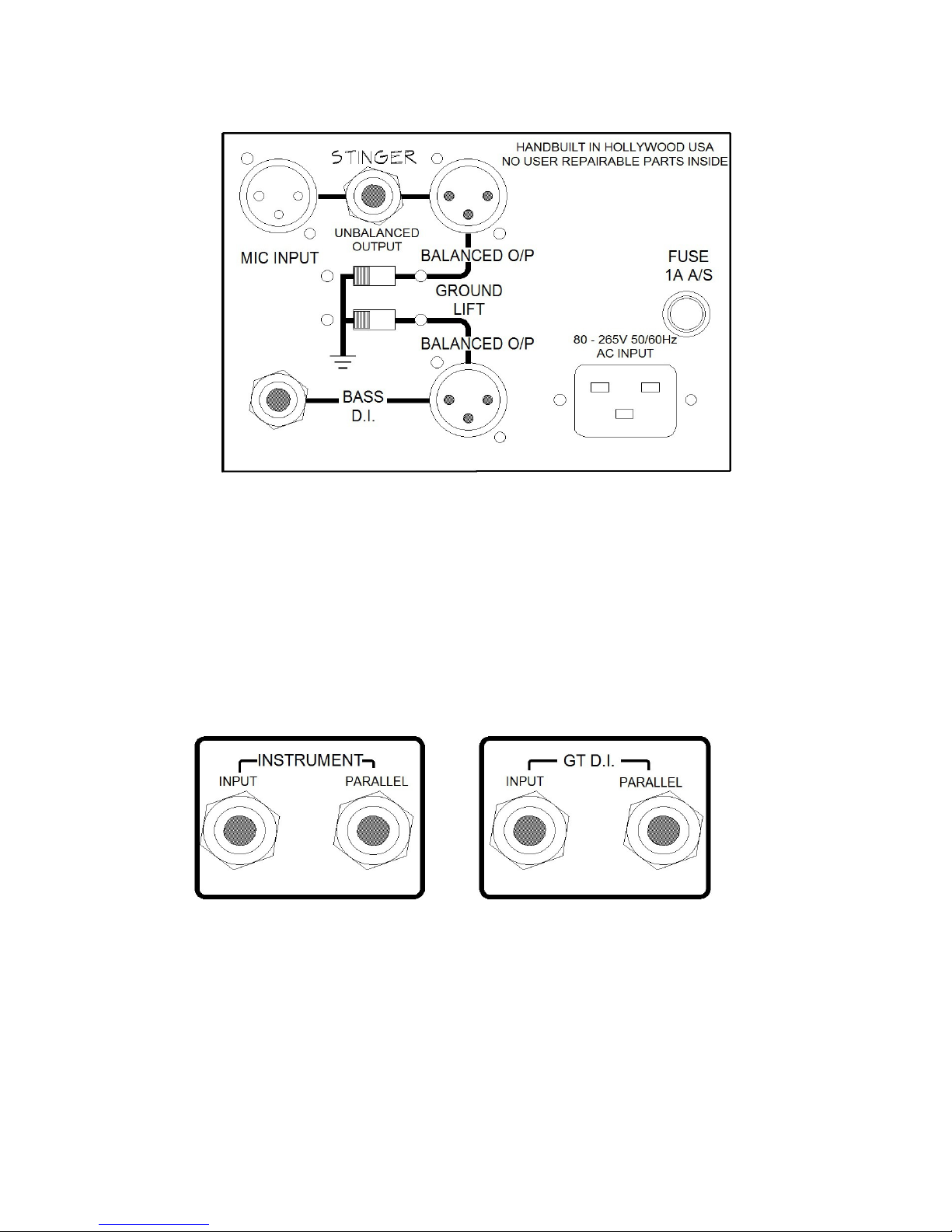
Connecting to the Aurora Stinger -
The Aurora Stinger has two independent audio paths, both have level controls
and XLR balanced and TRS unbalanced outputs. Both balanced outputs have
ground lift switches to eliminate ground loops when connecting to external
equipment.
At the top, the XLR female connector marked “Mic Input” can also
accommodate line inputs and has a gain range of -10dB to +80dB on the red
bar knob with additional control of +10dB to infinity via the 100mm travel
fader.
At the front are four mono jack sockets. In each pair the left sockets are
always inputs and the right is always a parallel output. Do not plug inputs
into the right hand jacks!
When a cable is plugged into the GT DI left input jack socket it will disable
the rear XLR input automatically.
The Instrument DI input is an independent circuit path
5
Table of contents


