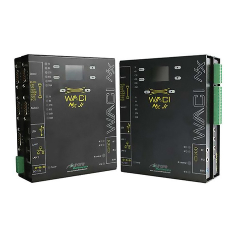
Aurora Multimedia WACI NX-22 Operating instructions

© Copyright 2009, Aurora Multimedia Corp.
All rights reserved, including the right to reproduce this guide or parts thereof, in any form without the
express written permission of Aurora Multimedia, Inc.
Trademarks and registered trademarks are the properties of their respective owners. Software and hardware
features and specifications subject to change without notice.

I. Quick Contents
I. QUICK CONTENTS................................................................................................................................................ 3
II. FULL CONTENTS..................................................................................................................................................4
III. INTRODUCTION..................................................................................................................................................6
IV. BOX CONTENTS.................................................................................................................................................. 7
V. HARDWARE SPECIFICATIONS........................................................................................................................ 8
VI. EXPANSION HARDWARE .............................................................................................................................. 17
VII. FACTORY DEFAULT CONFIGURATIONS......................................................................................... 18
VIII. QUICK START.................................................................................................................................................19
IX. USING THE WACI..............................................................................................................................................23
X. WEB SERVER FEATURES.................................................................................................................................26
XI. BOOT MENU REFERENCE..............................................................................................................................27
XII. ADMIN WEB PAGES........................................................................................................................................31
XIII. THE EVENT MANAGER................................................................................................................................54
XIV. REMOTE PROCEDURE CALLS...................................................................................................................87
XV. LIMITED 3 YEAR WARRANTY...................................................................................................................170
XVI. FCC PART 15 STATEMENT........................................................................................................................171
XVII. INDEX.............................................................................................................................................................172
3

II. Full Contents
I. QUICK CONTENTS................................................................................................................................................ 3
II. FULL CONTENTS..................................................................................................................................................4
III. INTRODUCTION..................................................................................................................................................6
IV. BOX CONTENTS.................................................................................................................................................. 7
BOX CONTENTS FOR THE NX-22......................................................................................................................................7
V. HARDWARE SPECIFICATIONS........................................................................................................................ 8
GENERAL SPECIFICATIONS................................................................................................................................................ 8
ABSOLUTE MAXIMUM RATINGS FOR HARDWARE...............................................................................................................10
HARDWARE PARTS OVERVIEW........................................................................................................................................11
DETAILED HARDWARE DESCRIPTIONS.............................................................................................................................. 12
VI. EXPANSION HARDWARE .............................................................................................................................. 17
VII. FACTORY DEFAULT CONFIGURATIONS......................................................................................... 18
DEFAULT NETWORK SETTINGS FOR LAN 1 & 2.............................................................................................................. 18
DEFAULT SERIAL SETTINGS............................................................................................................................................18
DEFAULT I/O SETTINGS ................................................................................................................................................18
VIII. QUICK START.................................................................................................................................................19
STEP 1: POWERING UP................................................................................................................................................19
STEP 2: DETERMINING WACI CONNECTION..................................................................................................................20
STEP 3A: CONNECTING THE NX-22 TO ALAN............................................................................................................20
STEP 3B: DIRECT CONNECTION IF STATIC IP IS SET ......................................................................................................21
STEP 3C: DIRECT CONNECTION WITH ASERIAL CABLE................................................................................................... 21
STEP 4: ACCESS THE WACI.......................................................................................................................................21
STEP 5: CONFIGURE WACI USING THE ADMIN WEB PAGES...........................................................................................22
IX. USING THE WACI..............................................................................................................................................23
TESTING HARDWARE..................................................................................................................................................... 23
UPLOADING FIRMWARE UPGRADES..................................................................................................................................23
VIEWING SERVER LOGS.................................................................................................................................................24
AUTOMATING TASKS (THE EVENT MANAGER)..................................................................................................................24
UPLOADING CUSTOM WEB PAGES...................................................................................................................................24
USING REMOTE PROCEDURE CALLS (RPCS)....................................................................................................................25
X. WEB SERVER FEATURES.................................................................................................................................26
XI. BOOT MENU REFERENCE..............................................................................................................................27
ACCESSING THE BOOT MENU WITH ASERIAL CONNECTION.................................................................................................27
0: DISPLAY CURRENT SETTINGS......................................................................................................................................27
1: RESTORE FACTORY DEFAULTS....................................................................................................................................28
2: CONFIGURE IP SETTINGS........................................................................................................................................... 28
3: CHANGE PASSWORD..................................................................................................................................................29
4: SET HOST NAME......................................................................................................................................................29
5: DOWNLOAD NEW FIRMWARE......................................................................................................................................29
6: LAMP TEST..............................................................................................................................................................30
7: MEMORY TEST.........................................................................................................................................................30
8: ERASE FILE SYSTEM..................................................................................................................................................30
9: OEM FUNCTIONS.....................................................................................................................................................30

XII. ADMIN WEB PAGES........................................................................................................................................31
SETUP......................................................................................................................................................................... 32
DIAGNOSTICS................................................................................................................................................................38
EVENTS (SEE SECTION: THE EVENT MANAGER)................................................................................................................49
FILES...........................................................................................................................................................................49
XIII. THE EVENT MANAGER................................................................................................................................54
OVERVIEW OF EVENTS, ACTIONS, & VARIABLES...............................................................................................................54
THE EVENT MANAGER WEB PAGE..................................................................................................................................55
EVENTS....................................................................................................................................................................... 57
ACTIONS......................................................................................................................................................................63
VARIABLES...................................................................................................................................................................71
FUNCTIONS...................................................................................................................................................................73
EXPRESSIONS................................................................................................................................................................76
XIV. REMOTE PROCEDURE CALLS...................................................................................................................87
RPC SERVER LOGS......................................................................................................................................................87
SYNTAX FOR HTTP POST..............................................................................................................................................87
FAULT CODES.............................................................................................................................................................. 89
USING MACROMEDIA FLASH...........................................................................................................................................90
VISUAL BASIC SCRIPTING...............................................................................................................................................92
NOTE ON ERROR CHECKING........................................................................................................................................... 92
RPC QUICK REFERENCE............................................................................................................................................... 93
ERROR INFORMATION METHODS....................................................................................................................................100
GENERAL INFORMATION METHODS................................................................................................................................101
NETWORK METHODS...................................................................................................................................................104
TELNET METHODS.......................................................................................................................................................108
LOGGING METHODS.................................................................................................................................................... 109
SERIAL METHODS....................................................................................................................................................... 112
RELAY METHODS........................................................................................................................................................115
DIGITAL I/O METHODS............................................................................................................................................... 117
IR METHODS............................................................................................................................................................. 119
EVENT MANAGER METHODS........................................................................................................................................ 125
EVENT METHODS........................................................................................................................................................127
ACTION METHODS...................................................................................................................................................... 146
VARIABLE METHODS...................................................................................................................................................161
XV. LIMITED 3 YEAR WARRANTY...................................................................................................................170
XVI. FCC PART 15 STATEMENT........................................................................................................................171
XVII. INDEX.............................................................................................................................................................172

III. Introduction
Welcome to the WACI world of powerful, non-proprietary, user-friendly control systems!
All puns aside, Aurora Multimedia has changed the way control systems are expected to behave. The
WACI (Web Access Control Interface, pronounced “wacky”) is one of the world's first standards-based,
non-platform-specific control systems. Not only does it work on just about any IP-based system, but it
can be developed on virtually any type of PC as well. The built-in web server, ftp file server, diagnostic
tools, and Event Manager allow the WACI to be free of proprietary tools and languages.
In addition to supporting standard languages such as HTML, DHTML, JAVA, FLASH, ASP, and Visual
Basic for creating control applications, Aurora Multimedia has provided powerful alternatives for the
non-programmer. For one, the built-in Event Manager runs server-side functions from web-based
interface without requiring a single line of code to be written. In addition, creating control interfaces with
Aurora's Flash-based program, called YIPI (Your IP Interface), is as easy as using a drawing program.
Furthermore, since the diagnostics and Event Manager are served up using a standard, non-proprietary
web server, any device equipped with a standard web browser, be it PC, Pocket PC, Palm, or Mac, is now
enabled to access your system.
The WACI does all this with a powerful 32 bit engine with 32 bit pipeline memory in a small box that can
fit just about anywhere. The power guarantees that small or large files can be processed without delay in
a real-time application with network traffic. Systems with less power and less memory bog down quickly
on server requests, but this is no problem for the WACI, which has enough power to support the smooth
performance of attractive, friendly user interfaces as well.
Aurora Multimedia did not stop at the software user interfaces to increase the serviceability and value of
the WACI. Other simple but effective innovations include C Type relays (normally open & closed
physically available), which allow creative use such as a switcher or to expand the amount of discrete
ports; RS-232 transmit from the IR to allow additional control from alternate ports; IR Input for just about
any IR remote to be used with the NX-22; Digital Input, and Digital Output functions from a single port;
Micro SD memory functionality; USB 2.0 port to add additional capabilities such as storage, Bluetooth,
and much more.
With the NX-22, Aurora Multimedia takes the control system industry to a new era of easy-to-use,
powerful, and cost-effective tools, paving the way for new possibilities in the way systems are operated.

IV. Bo Contents
Box Contents for the NX-22
12v 15 Watt Supply
International Supply
Kit
2 IR Port Emitters
NX-22 Device Power Adapters IR Emitters

V. Hardware Specifications
General Specifications
NX-22 Notes
Size 1.75” H x .4” W x 4.51” D √
Weight 0. lbs. √
Power
Adapter
12V DC 15watt
Processor 32-Bit √ 900 MIPS Normal Mode
Co-
Processing
√
Cipher √ Supports DES, 3DES,
AES
Implements entire IPsec
packet processing in
hardware – no CPU
burden
True Random Number
Generator (RNG) in
hardware
Robust security is ideal
for most business network
environments – meets
U.S. government and
banking industry
requirements
IR (True Trigger) √ Highly Accurate IR
Capture and reproduction
Memory Total RAM 12 M 667DDR2 32 bit wide
Total Flash 256M
Available Flash 220M Available memory may
vary, based on firmware
version.
Display 106 x 56 Pixels Backlit √
Ports LAN Network Adapter (RJ-
45 / Ethernet)
2 10/100MBits Auto MDX
POE on LAN1
USB OTG (On-The-Go) v2.0 1 400MBits Host or Client
RS-232/422/4 5 (DB-9) 2 15KV Protection, 115KB

Max
Infrared Outputs (IR) 2 30KHz – 2MHz
RS-232 TX as well
Infrared Input 1 IR input device triggers
Digital Input / Digital Output 2 High Impedance
200ma Sink Open Drain
Relay (SPDT) 2 C-Type (NO, NC, CP)
Audio Unbalance Input 1 20Hz-20Khz
Unbalanced Output 1 20Hz-20Khz
Monitoring 32-Bit Internal Clock/Calendar √
IR Learner √ 30KHz – 2MHz
xpansion Micro SD √ Memory up to 16GB
USB Host 2.0 √ Memory / 02.11b/g/n
Network
Access
Web & FTP √
Specifications subject to change without notice.

bsolute Maximum Ratings for Hardware
Below is a summary of the minimum, maximum, and typical values for the hardware.
These are maximum ratings only. Operation of the device at or above these ratings for extended periods
of time may affect reliability.
Min Typ Max Units Notes
WACI Input Voltage + +12 +1 V WACI NX: Min. 15watt supply
Storage Temperature -20 +55 °C
Digital I/O Input 0 12 V Zener protection for higher voltages
Digital I/O Output 0 12 V Can source up to 20mA at 3V and
has open collector mode for higher
voltages.
Relay 0 2 A Max 30V DC

Hardware Parts Overview
NX-22 Parts Overview
# Short Description More Info
1 Built-in LCD display for setup and diagnostics
2 LED Indicators Power, IR In, Serial, IR, Relays, I O
3 Six button menu navigation
4 IR Learner Port
5 Reset paperclip button hole
6 Micro SD Memory Expansion
7 USB 2.0 Host
8 IR In Port
9 Power Adapter Port
10 Two 10 100 Auto-MDX LAN Ports (LAN1 has capability POE)
11 USB 2.0 On-The-Go Port
12 Audio Line In
13 Audio Line Out
14 Two RS-232 422 485 Serial Ports
15 IR Ports 1&2
16 Relay Ports 1&2 (Normally Open, Center Pin, Normally Closed)
17 I O Ports 1&2

Detailed Hardware Descriptions
Power Indicator and LCD
A green power indicator is available on both the NX-22. The power indicator is lit whenever power is
applied to the WACI. The LED will stay solid if the system is OK.
Power dapter
The power adapter is included with the WACI NX. The 15 watts supplied is more then enough to power
the WACI NX as well as certain USB add-on modules
Power Port
The WACI NX is powered using the included Power Adapter. The smaller end of the Power Adapter is
plugged into this port. You should plug the Power Adapter into this port after the network cable has been
attached.
Green Power
The green LED indicates that the WACI is powered and operating.
LCD Display
The 106 x 56 backlit pixel based display helps with the diagnostic and setup of the WACI NX.
ccess Boot Menu
Press and hold the any of the 6 buttons for 5 seconds to bring up the Boot Menu while plugging in the
power connector. For more information on the Boot Menu see Boot Menu Reference on page 27. A null
RS-232 cable will be needed for the boot menu to a PC running a terminal program.
Serial Ports
Serial port interfaces are available on both the NX-22.
Serial Ports 1 & 2
The WACI NX has two (2) serial ports that enable RS-232 and RS-422/485 communications, supporting
a wide range of compatible electronics.
The actual connectors on the WACI are DB-9 male ports.
The device or cable you wish to connect to the WACI NX should be a DB-9 female connector.

Serial Port Pin-Out Diagram
Pin RS-232 RS-422/485
1 NC RX+
2 RX
3 TX
4 DTR TX-
5 GND GND
6 DSR
7 RTS TX+
CTS
9 NC RX-
LED Indicators for Serial Ports 1 & 2
There are two (2) sets of LEDs, one set for each serial port. Each set consists of two (2) red LEDs that
indicate activity on the pins.
When using RS-232 communications, the two LEDs indicate activity on the TX and RX pins.
When using RS-422/485 communications, the LEDs indicate activity on the corresponding TX+, TX-,
RX+, and RX- pins.
RS-422 Operation:
When using RS-422 operation the RX+ and RX- should have a 120 Ohm resistor across the two pins.
Also, RS-422 operation must be selected in the setup page in order for it to properly work.
RS-485 Operation:
When using the RS-485 operation the RX+ and TX+ should be tied together as well as the RX- and TX-.
There should be a 120 Ohm termination resistor across the two pins. Also, RS-485 operation must be
selected in the setup page in order for it to properly work.

Network Interface
The WACI NX has two 10/100 Auto MDX Ethernet ports. LAN1 is POE (Power Over Ethernet) capable.
The Auto MDX allows the use of null or straight through LAN cables to the ports.
L N Port
The WACI may be connected to a network using a standard RJ-45 Ethernet cable in this port. Both 10Mb
and 100Mb connections are supported.
Port RJ-45
1 TX+
2 TX-
3 RX+
4 NC
5 NC
6 RX-
7 NC
NC
LED Indicators
The green LED on the LAN port indicates that a network has been detected.
The yellow LED on the LAN port indicates that data is being transmitted or received through the port.
Relays
The Relays on the NX-22 have two connection types: N.O. = Normally Open and N.C. = Normally
Closed. The “Normal” position is the state of the relay when it is not turned on (not energized). You can
turn the relays on and off using the relay diagnostic page (see Relay Diagnostics, page 45), using an
Event Manager “Relay Action” (see Relay, page 67), or through an RPC method call (see Relay Methods,
page 115).
Relay Ports 1&2
Each port consists of 3 lines: NO (Normally Open), CP (Center Pole), NC (Normally Closed). Connect
the incoming wire to the CP connection, and the outgoing wire to either of the other two ports (NO or
NC). The outgoing port you choose depends on which type of connection you wish to consider “Normal”.
LED Indicators for Relay Ports 1&2
Two red LEDs indicate activity for each Relay Port.

Digital I/O 1&2
Each I/O port is capable of being used in one of two different configurations; Digital Input, and Digital
Output. These modes of operation can be configured in the built in setup pages of the WACI NX or via
RPC commands.
Digital Input
The Digital Input is used to read a digital voltage level. It can read 0V (=0) or 3V (=1). Higher voltages
are clamped to 3V. The digital input is perfect for applications requiring simple on/off detection such a
contact switch. By default the port is high impedance for the most flexibility. The setup page can also
allow a pull-up configuration. If the port is left as is then the device connected to the digital input must
supply the high and low voltages.
You can see the state of the Digital Input port using the DIO diagnostic page (see Digital I/O Diagnostics,
page 46) or through an RPC method call (see Digital I/O Methods, page 117).
Digital Output
The Digital Output is used as an open drain and can sink up to 200mA. Setting the port to 0 will leave
sink the input to ground. Setting the port as a 1 will put the port into a high impedance state. The digital
output can be used for triggering relays, LEDs, or any device that will not require more then 200mA of
current.
You can change the state of the Digital Output port using the DIO diagnostic page (see Digital I/O
Diagnostics, page 46) or through an RPC method call (see Digital I/O Methods, page 117).
I/O GROUND Line
To operate properly, the device connected to the input port must be connected to both the GND line of the
connector block as well as one of the two input ports.
LED Indicators for I/O Ports (1&2)
The LEDs indicate that the voltage is on the port. It will be either on (voltage present) or off (no voltage
or less than 1V).
IR Ports
The two (2) IR ports on the NX-22 are used to send infrared commands to devices that can be controlled
using a standard IR remote control. To control a device, connect one of the IR emitters to the IR sensor of
the device to be controlled. In addition the IR port can be used a one way RS-232C (TX only) at rates up
to 115k.
To program the NX-22 to send IR commands, you’ll need to download one of the device appropriate
.WIR files, or use the IR Learner to learn the remote for the device.

Use the IR Diagnostics page (see Managing Learned Commands, page 43), an IR Action (see IR Port,
page 67), or an RPC command (see IR_SendCommand ( Port, Group, Command ), page 119) to send IR
commands out the IR ports.
IR Emitters
The IR Emitters are small cables with an IR Emitter at one end and a small audio style plug at the other.
The emitters plug into the IR ports. The emitter end attaches to the device to be controlled. When the
WACI is sending a command to the device through the emitter, the LED on the back of the emitter will
light up.
IR Ports
There are two IR ports on the NX-22. They are located across the Ethernet ports. Plug the IR Emitters
into these ports.
LED Indicators for IR Ports
When an IR command is sent out an IR Port, the LED for that port is lit.
IR Learner
The IR Learner is used to learn the IR codes from a device’s remote control. It can read many different
types of remotes. If it has trouble with your remote, you may need to download from Aurora Multimedia
a .WIR file that is specific to the device.
IR Learner Port
Point your remote at the window on the lower right front of the WACI NX to learn an IR command for
your remote. You’ll need to use the IR diagnostics page to learn the command (see IR Learning, page 41).
IR Learner LED
The LED is lit during the learning process when an IR signal is detected on the IR sensor within the
WACI NX. When the process is first started the LED will glow in and out slowly until a signal is
received. If the remote is too far away it will continue to glow slowly. The correct distance for the
strength of the signal is usually about 6” and will turn the LED solid when the proper distance is
achieved. If the remote is too close then the LED will blink fast.

VI. E pansion Hardware
The WACI NX control system has the ability to expand its capabilities using the docking USB 2.0 Host
and USB 2.0 OTG connectors. This expansion bus is capable of high speed connection up to 400Mbps to
pass through small or large amounts of data for additional features like additional ports, Bluetooth Voice
Lift, WIFI, and much more. With the use of a USB Hub even more ports can be added. Always check
with the latest specification of the expansion device to see feature, power and docking requirements.
Specifications are subject to change without notice.

VII. Factory Default
Configurations
Default Network Settings for L N 1 & 2
DHCP Enabled Yes
IP Address From DHCP
Subnet Mask From DHCP
Gateway From DHCP
Host Name WACI
Password admin
Default Serial Settings
Baud rate 9600 baud
Data bits
Parity bits None
Stop Bits 1
Signal Level RS232
Handshaking None
Default I/O Settings
I/O Port Digital Input

VIII. Quick Start
STEP 1: Powering Up
Locate the power adapter that came with your WACI. Plug the small end into the power supply port
(labeled “Power”) on the lower left side on the back of the WACI, and the large plug into a wall socket or
compatible power supply.
You should observe the following behavior in this order:
•Once power is applied the green Power LED will immediately light as well as the LCD
backlight. It will remain lit while the WACI is plugged in. All other LEDs will be off and the
LCD will have a message “Initializing”.
•The WACI will run through its internal hardware diagnostics.
•After approximately 5-10 seconds (assuming the self-test passes), on the LCD will display
firmware version and current IP addresses for the LAN ports. If a LAN port is set to DHCP it
may take longer as it will try to get an IP address from the DHCP server. Static IP addresses
will allow the WACI NX to boot within 10 sec.

STEP 2: Determining W CI Connection
Decide how you would like to connect to your WACI to configure it:
Connection Type Why use this connection
type?
What do I do next to
connect my WACI
this way?
Connect the WACI NX to a LAN Network and
configure it using a PC on the Network.
This is the typical set up for
general WACI NX use.
STEP 3A: Connecting
the NX-22 to a LAN
Connect the WACI NX directly to a PC using an
Ethernet cable.
You do not have a LAN
network, and you need to
access all Admin Web Pages
for configuration.
SKIP to STEP 3B:
Direct Connection if
Static IP is Set
Ignore step 3A.
Connect the WACI directly to a PC using a
serial data transfer cable (AKA null modem
cable
You do not have a LAN
network, and you only need
to access to the basic setup
configuration found in the
Boot Menu.
or
You need to set up the
manual IP address for a static
LAN network
SKIP to STEP 3C:
Direct Connection with
a Serial Cable
Ignore steps 3A & 3B.
STEP 3 : Connecting the NX-22 to a L N
The WACI can be configured to use either a static IP, or a dynamically allocated one. By default, the
WACI is set to DHCP for both LAN 1&2. An IP of 0.0.0.0 will be displayed for a LAN port if a DHCP
address is not acquired. (see Default Network Settings, page 18).
If your network is configured to support the default network (IP) settings, you may immediately connect
your hub or router to the WACI using an Ethernet cable with an RJ-45 connector.
If your network is set up to use static IP then you’ll need to change the WACI’s IP address through the
Boot Menu (see Boot Menu Reference, page 27).
Some networks use DHCP to automatically issue IP addresses to machines connected to it. If your
network is setup to use DHCP, then you’ll need to configure the WACI to use DHCP. There are two
Table of contents
Other Aurora Multimedia Control System manuals
Popular Control System manuals by other brands

Honeywell
Honeywell 900CS10-00 Installation

Motorline professional
Motorline professional Sintact Operation manual
Crestron
Crestron FlipTop FT2 Series quick start guide
Emec
Emec DIN DIGITAL CD operating manual
John Crane
John Crane API PLAN 74 STEAM Installation, operation & maintenance instructions

Addi-Data
Addi-Data APCI-8001 Commissioning manual

