PAW HeatBloC K33R Owner's manual

Installation and Operation Instructions
HeatBloC® K33R
DN 25 / DN 32
DN 25 DN 32
PAW GmbH & Co. KG
Böcklerstraße 11, 31789 Hameln, Germany
Phone: +49-5151-9856-0, Fax: +49-5151-9856-98
07/2023 993x0463x-mub-en - V03 1

Table of Contents
1 General Information...................................................................................................3
1.1 Scope of these instructions........................................................................................3
1.2 Designated use........................................................................................................... 3
2 Safety instructions......................................................................................................4
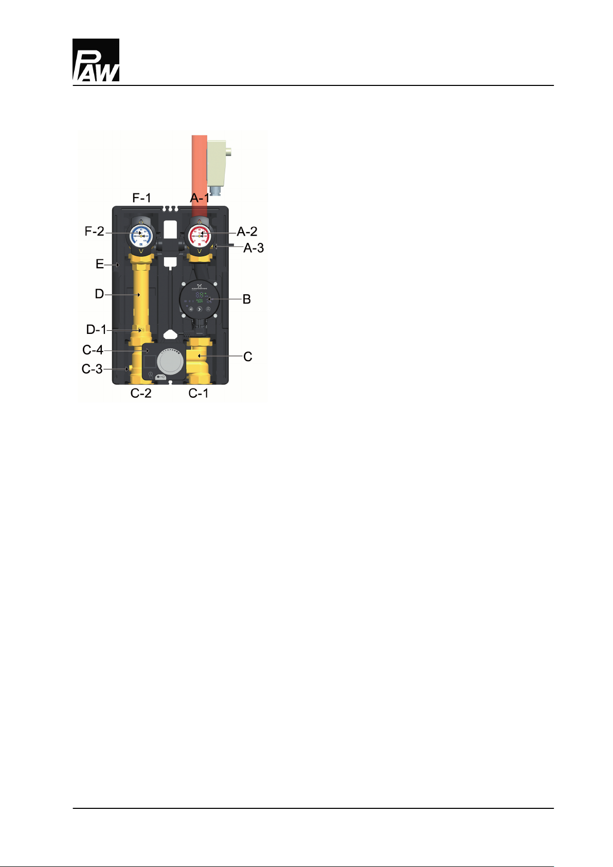
3 Product description.................................................................................................... 5
3.1 Equipment...................................................................................................................6
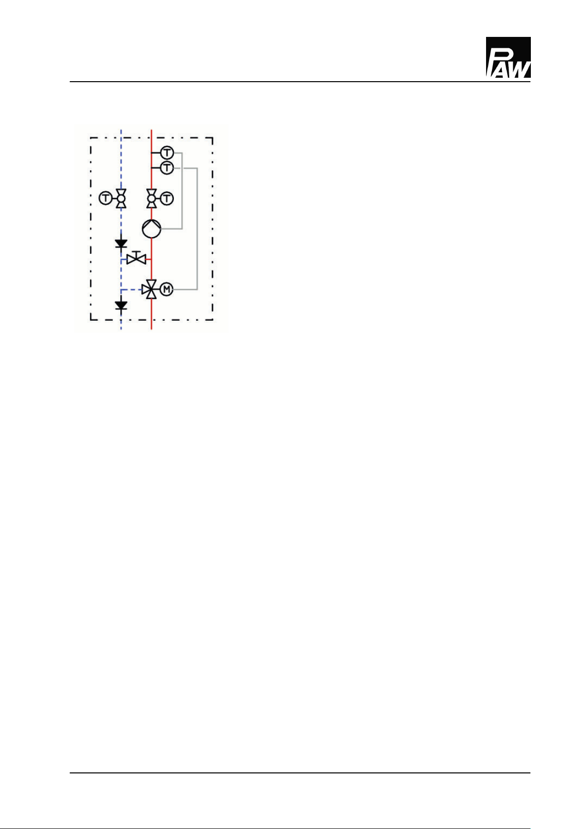
3.2 Function.......................................................................................................................7
3.2.1 Check valve and non-return valve.............................................................................8
3.2.2 Pump [specialist].........................................................................................................9
3.2.3 3-way mixing valve [specialist]..................................................................................9
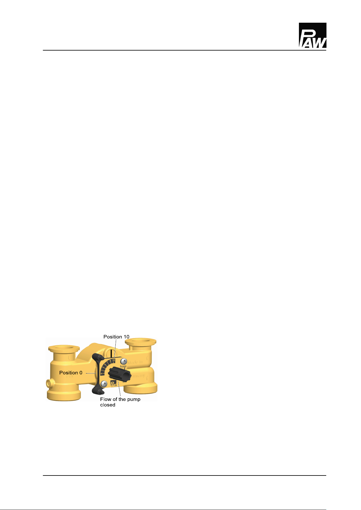
3.2.4 Change of the flow line [specialist]........................................................................... 10
3.3 Constant temperature controller PKR6.................................................................... 13
3.4 Setting of the constant temperature controller PKR6 as a return flow
temperature maintenance.........................................................................................13
4 Mounting and installation [specialist]...................................................................... 15
4.1 Installation and commissioning of the HeatBloC®...................................................15
4.2 Accessories: Cutting-ring compression fitting (not included in the scope of
delivery).......................................................................................................................18
5 Scope of delivery [specialist]..................................................................................... 19
5.1 Spare parts DN 25....................................................................................................... 19
5.2 Spare parts DN 32....................................................................................................... 21
6 Technical data............................................................................................................. 23
6.1 Pressure drop and pump characteristic curves DN 25.............................................25
6.2 Pressure drop and pump characteristic curves DN 32.............................................25
7 Disposal....................................................................................................................... 26
Table of Contents
07/2023 993x0463x-mub-en - V03 2

1 General Information
Carefully read these instructions before installation and commissioning.
Save these instructions in the vicinity of the installation for future reference.
1.1 Scope of these instructions
These instructions describe the installation, commissioning, functioning and the operation of a mixed
HeatBloC®.
For other components of the installation, such as the pump, the controller or the modular distribution
manifold, please observe the instructions of the corresponding manufacturer. The chapters called
[specialist] are intended for specialists only.
1.2 Designated use
The product may only be used in heating circuits taking into consideration the technical limit values
indicated in these instructions.
It must not be used in drinking water applications.
Improper usage excludes any liability claims.
This product complies with the relevant directives and is therefore labelled with the CE mark.
The Declaration of Conformity is available upon request, please contact the manufacturer.
Only use PAW accessories with the product.
1 General Information
07/2023 993x0463x-mub-en - V03 3

2 Safety instructions
The installation and commissioning as well as the connection of electrical components require
technical knowledge commensurate with a recognised vocational qualification as a fitter for
plumbing, heating and air conditioning technology, or a profession requiring a comparable level of
knowledge [specialist].
The following must be observed during installation and commissioning:
●relevant local and national regulations
●accident prevention regulations of the professional association
●instructions and safety instructions mentioned in these instructions
CAUTION
Personal injury and damage to property!
The product must only be used in heating circuits filled with heating water according
to VDI 2035 / Ö-Norm H 5195-1.
►The product must not be used in drinking water applications.
NOTICE
Material damage due to mineral oils!
Mineral oil products cause lasting damage to seals made of EPDM, whereby the sealant properties
are lost. We do not assume liability nor provide warranty for damage to property resulting from
sealants damaged in this way.
►It is imperative to prevent the EPDM sealing elements from making contact with substances
containing mineral oils.
►Use a silicone- or polyalkylene-based lubricant free of mineral oil such as Unisilikon L250L
and Syntheso Glep 1 from Klüber or a silicone spray.
2 Safety instructions
4 993x0463x-mub-en - V03 07/2023

3 Product description
The HeatBloC® is a preassembled group of fittings for heating circuits. The pump can be isolated by
means of the ball valves and the mixing valve. The pump can thus be maintained easily without
draining the heating circuit system.
The HeatBloC® is designed such that it can be directly mounted onto a PAW distribution manifold or a
mounting plate. With transition connections, HeatBloC®s can also be mounted on modular
distribution manifolds of other dimensions.
This product is prepared for the operation as a supply group, such as for radiant panel heating systems
(e.g. radiant floor heating systems) - with constant flow temperature. The mixing valve bypass is
completely open so that the control range of the mixing valve can be completely used even if the flow
temperatures are low. In order to protect the connected radiant panel heating system from
overheating, a safety temperature limitation is included in the scope of delivery.
The product can be easily converted into a group for return flow temperature maintenance. It can
then be used with solid fuel boilers.
3 Product description
07/2023 993x0463x-mub-en - V03 5

3.1 Equipment
A-1 Flow to the consumer circuit
A-2 All-metal thermometer with immersion sleeve,
integrated in the ball valve (flow)
A-3 Temperature sensor (Pt1000)
B Heating pump
C 3-way mixing valve with adjustable bypass
0-50 %
C-1 Flow from the heat generator
C-2 Return to the heat generator
C-3 Non-return valve, can be opened
C-4 Constant temperature controller PKR6
D Return pipe
D-1 Check valve, can be opened
E Design insulation with optimised function
F-1 Return from the consumer circuit
F-2 All-metal thermometer with immersion sleeve,
integrated in the ball valve (return)
3 Product description
6 993x0463x-mub-en - V03 07/2023

3.2 Function
3-way mixing valve with bypass 0-50%
The flow temperature of the heating circuit is controlled by
the integrated mixing valve. Hot water from the boiler and
cold return water are mixed to obtain the desired flow
temperature of the heating circuit. The mixing valve is
adjusted by means of the constant temperature controller
PKR6.
Due to the premixing rate that must be adjusted at the
bypass of the mixing valve, a certain amount of cold return
water is added to the flow water. The 3-way actuator can
thus work over the whole adjustment range (0-100 %),
although only a small amount of water from the boiler is
necessary.
Application range:
●Consumer circuits with a
considerably lower flow
temperature than the boiler
flow temperature
●Consumer circuits with high
flow rates, e.g. radiant floor
heating and radiant panel
heating systems
●In connection with the
constant temperature
controller PKR6 for return flow
temperature maintenance
(then, the bypass is closed)
Example:
Panel heating systems operate on a low temperature
level with small temperature differences, but with high
flow rates. It is therefore sufficient to add a small amount of
hot water to the "warm" return water.
For the use as a return flow temperature maintenance,
the bypass in the mixing valve must be completely closed
so that the entire boiler output is available for the
consumer circuits.
3 Product description
07/2023 993x0463x-mub-en - V03 7

3.2.1 Check valve and non-return valve
The product is equipped with a check valve and with a non-return valve. The valves can be opened.
operation
During operation, the markings must point to "Z".
●The check valve and the non-return valve are
closed.
●Flow only in the direction of the arrow.
filling, draining, venting
For filling, draining and venting, the markings must
be directed to "A".
●The check valve and the non-return valve are
closed.
●Flow in both directions.
3 Product description
8 993x0463x-mub-en - V03 07/2023

3.2.2 Pump [specialist]
The pump can be completely isolated. It can be replaced and maintained without draining the heating
circuit system.
Isolation of the pump
1. Disconnect the expansion tank from the installation.
2. Close the ball valves in the flow and the return (A-2, F-2).
3. Remove the constant temperature controller PKR6 from the mixing valve.
4. Turn the bypass screw of the mixing valve such that the slot is in a vertical position.
5. Turn the nose of the valve cock such that the flow to the pump is closed (for flow on the right:
nose points downward, for flow on the left: nose points to the right; see below).
The mixing valve is now closed and drop tight.
3.2.3 3-way mixing valve [specialist]
The 3-way mixing valve (C), driven by an electric actuator, adjusts the flow temperature of the
consumer circuit to the required value by means of the flow sensor and the controller.
The mixing valve is equipped with a bypass which must be operated separately. Via this bypass, cold
return water is added to the flow of the HeatBloC®. This can result in an increase of the flow rate of the
HeatBloC®.
Mixing valve with flow on the right:
Position 10 / Bypass closed:
passage, no mixing
flow temperature consumer = flow temperature heat
generator
Position 0:
100% mixing
flow temperature consumer = return temperature
consumer
3 Product description
07/2023 993x0463x-mub-en - V03 9

1. During commissioning, determine the optimum bypass position for the operation of the
installation. Find out and check the correct adjustment through a trial-and-error process.
If the slot of the bypass screw is in a vertical
position, the bypass is closed.
If the HeatBloC® K33R / K34R is used as a return
flow temperature maintenance, the bypass must
be closed!
If the slot of the bypass screw is in a horizontal
position, the bypass is completely open.
A maximum flow rate from the return to the flow
line is thus enabled. This adjustment may be
necessary for radiant floor heating systems which
require a very high water flow volume. Because of
the bypass, the flow temperature decreases and
the control is affected.
2. Check the position of the bypass during operation. Make sure that the flow rate is sufficient and
that the desired temperature is reached.
3.2.4 Change of the flow line [specialist]
Dismounting of the mixing valve
1. Take off the thermometer handles (A-2, F-2) and remove the insulating front shell.
2. Take the group of fittings out of the insulating back shell.
3. Dismount the mixing valve (C).
3 Product description
10 993x0463x-mub-en - V03 07/2023

Retrofitting of the mixing valve
1. Loosen the screw (1).
2. Take off the rotary knob (2) from the cock rod.
3. Loosen the screws (3).
4. Remove the cover plate (4).
5. Loosen the two screws (5).
6. Remove the front plate (6).
7. Extract the sealing bush (7) with the cock plug (8) from the housing of the mixing valve.
8. Loosen the screws (10) on the rear side of the mixing valve.
9. Take off the cover (9) on the rear side of the mixing valve and fix it on the other side of the mixing
valve by using the screws (10).
10. Insert the sealing bush (7) with the cock plug (8) into the channel of the mixing valve.
3 Product description
07/2023 993x0463x-mub-en - V03 11

11. Screw down the front plate (6) using the screws (5).
Mixing valve with flow on the right Mixing valve with flow on the left
12. Turn the cover plate (4) in such a way that the marking PAW is at the bottom and that the scale is
positioned as shown in the figure above.
13. Fix the cover plate (4) by using the screws (3).
14. Put the rotary knob (2) onto the cock rod.
Only for K34R: Turn the cock plug to the mixing valve position "5". Then, the controller PWR6 can
directly be mounted.
15. Fix the rotary knob (2) on the cock plug (8) by using the screw (1).
Retrofitting and commissioning of the heating circuit
1. Interchange the return pipe (D) and the flow pipe with the pump (B).
Consider the flow direction of the pump!
Turn the pump head such that the terminal box is directed to the top or to the centre of the
group of fittings.
2. Dismount and interchange the ball valves. The temperature sensor must be mounted in the flow
ball valve!
3. Mount the HeatBloC® and connect it to the installation.
4. Check all union nuts before commissioning and firmly tighten them if necessary.
5. Mount the insulation only after having carried out a pressure test. Mount the thermometer
handles (A-2, F-2) in a final step.
3 Product description
12 993x0463x-mub-en - V03 07/2023

3.3 Constant temperature controller PKR6
The PAW constant temperature controller PKR6 is prepared for the direct mounting onto the 3-way
bypass mixing valve of the product.
When the constant temperature controller PKR6 is delivered, it is preset for the constant temperature
control of a radiant panel heating system (nominal flow temperature = 30 °C) with the flow line on the
right.
3.4 Setting of the constant temperature controller PKR6 as a return flow temperature
maintenance
Application Flow line required modifications at
the HeatBloC®
required adjustments at
the controller PKR6 - see
separate instructions
Radiant panel
heating
pump on the right,
transports upwards —nominal flow temperature is
30 °C - adjust, if necessary
pump on the left,
transports upwards
retrofitting of the mixing
valve and of the HeatBloC®
for flow on the left (see 3.2.2
and 3.2.3)
change the direction of
rotation to "left"
nominal flow temperature is
30 °C - adjust, if necessary
Return flow
temperature
maintenance
pump on the right,
transports upwards
close mixing valve bypass
interchange thermometers
set the scheme "return
temperature"
nominal return temperature
is 60 °C - adjust, if necessary
pump on the left,
transports upwards
retrofitting of the mixing
valve and of the HeatBloC®
for flow on the left (see 3.2.2
and 3.2.3)
close mixing valve bypass
set the scheme "return
temperature"
change the direction of
rotation to "left"
nominal return temperature
is 60 °C - adjust, if necessary
3 Product description
07/2023 993x0463x-mub-en - V03 13

Mounting of the constant temperature controller PKR6 for mixing valve with flow on the right:
Fig. 1
Fig. 2
Fig. 3
1. Turn the rotary knob of the mixing valve into
position "5“.
2. When the constant temperature controller is
delivered, it is in centre position.
By disengaging the gear (●push○), you can
adjust the controller at the rotary knob. In this
way, you can test if the actuator / rotary knob is
mounted correctly.
3. Mount the stop bolts, if necessary.
4. Push the constant temperature controller PKR6
on the rotary knob of the mixing valve and
mount it onto the two stop bolts (fig. 1).
The constant temperature controller must be
mounted according to figure 2.
5. Re-engage the gear (●push○).
6. Set the constant temperature controller to
automatic operation mode.
7. Connect the flow temperature sensor (mounted
in the flow ball valve) with the constant
temperature controller.
8. After the mounting is completed, the safety plug
can be plugged into a corresponding socket
(fig. 3).
9. For the commissioning, please observe the
instructions of the controller.
3 Product description
14 993x0463x-mub-en - V03 07/2023

4 Mounting and installation [specialist]
The HeatBloC® can either be mounted on a distribution manifold or on a wall bracket. The distribution
manifold and the wall bracket are opt. accessories and are thus not included in the scope of delivery.
NOTICE
Damage to property!
The installation site must be dry, stable, frost-proof and protected against ultraviolet radiation in
order to prevent material damage of the installation.
4.1 Installation and commissioning of the HeatBloC®
The HeatBloC® can be mounted
Option 1: on a PAW modular distribution manifold.
4 Mounting and installation [specialist]
07/2023 993x0463x-mub-en - V03 15

Option 2: on a mounting plate with transition
thread connections.
Option 3: directly on a wall bracket
Please observe the separate and respectively corresponding instructions regarding the installation of
the distribution manifold, of the mounting plate and of the wall bracket.
4 Mounting and installation [specialist]
16 993x0463x-mub-en - V03 07/2023

1. Take off the thermometer handles (A-2, F-2)
and remove the insulating front shell of the
HeatBloC®.
2. Unscrew the nuts on the lower connections
of the HeatBloC® and take out the sealing
rings.
If a PAW modular distribution manifold or
transition connection is used:
3. Put the two nuts over the flanges.
4. Insert the sealing rings into the nuts.
5. Put the HeatBloC® onto the two nuts.
6. Tighten the nuts. Make sure that the nuts
do not get jammed and that the sealing
rings do not slip.
7. Connect the HeatBloC® to the installation
by using the pipes. The installation to the
piping must be carried out without any
tension.
8. Connect the pump.
9. Carry out a pressure test and check all
thread connections.
10. Mount the insulating front shell and the
thermometer handles (A-2, F-2).
4 Mounting and installation [specialist]
07/2023 993x0463x-mub-en - V03 17

4.2 Accessories: Cutting-ring compression fitting (not included in the scope of delivery)
The connection to the heating installation can be carried out fast, pressure-proof and without
soldering if you use the optionally available compression fittings.
1. Push the union nut ②and the cutting ring ③
onto the copper pipe ①. The pipe must protrude
at least 3 mm from the cutting ring in order to
ensure the force transmission and the sealing.
2. Insert the support sleeve ④into the copper pipe.
3. Insert the copper pipe with the plugged-on
individual parts ②, ③and ④as far as possible
into the body of the compression fitting ⑤.
4. First, screw the union nut ②manually.
5. Tighten the union nut ②by rotating one full
turn. Secure the body of the compression fitting
⑤against distort in order to avoid damaging the
sealing ring.
Not included in the scope of delivery!
4 Mounting and installation [specialist]
18 993x0463x-mub-en - V03 07/2023

5 Scope of delivery [specialist]
NOTICE
Serial number
Complaints and requests/orders of spare parts will only be processed with information on the serial
number! The serial number is placed on the return pipe of the product.
5.1 Spare parts DN 25
5 Scope of delivery [specialist]
07/2023 993x0463x-mub-en - V03 19

Position Spare part Item number
1 Contact thermostat N00083
2 Thermo ball valve DN 25, F1" x 1" int. thread, snap-in assembly N00244
3 Temperature sensor Pt1000-B, screw-in sensor 9 mm, G¼" N00230
4 Thermometer handle for thermometer ball valve 1" x ¼" N00248
5 Dial thermometer, red scale, d = 50 mm, 0-120 °C N00242
6 Union nut G 1½" N00269
7 Gasket 1", for threaded connection 1½" N00131
8 Pump see following table
9 Constant temperature controller PKR6, 6 Nm, 230 V, 3-level control 703601
10 3-way bypass mixing valve DN 25, F1" x 1½" ext. thread N00020
11 Brass pipe DN 25, 2 x 1½" ext. thread, 180 mm, with check valve and
seals
N00018
12 Dial thermometer, blue scale, d = 50 mm, 0-120 °C N00243
13 Insulation for HeatBloC® DN 25 N00016
no pos. Sealing set for mixing valve 37013
Item no. heating circuit Pump Item no. pump EEI
360463WP6 Wilo Para SC 25/6-43 N00259 < 0.20
360463WP8 Wilo Para SC 25/8-60/O N00271 < 0.20
360463WN06 Wilo Yonos PICO 25/1-6 N00214 < 0.20
360463GL9 Grundfos UPML 25-105 Auto N00396 < 0.23
360463GM6 Grundfos UPM3 Auto L 25-70 PP3 N00237 < 0.20
360463GH6 Grundfos Alpha2.1 25-60 N00236 < 0.17
360463 without pump / /
5 Scope of delivery [specialist]
20 993x0463x-mub-en - V03 07/2023
Other manuals for HeatBloC K33R
1
Table of contents
Other PAW Control System manuals
Popular Control System manuals by other brands

herdstar
herdstar BinTrac BTB-200 Operation manual

GE
GE Multilin MM300 Installation Recommendations

Techno CNC Systems
Techno CNC Systems BT1212 user manual

Bailey
Bailey infi 90 IISAC01 Instruction

Elsner
Elsner 70191 Installation and operation

Shenzhen Guanhong Automation
Shenzhen Guanhong Automation SZGH-CNC990TDb series user manual

Autotrol
Autotrol 255 Series Installation, operation and maintenance manual

Raven
Raven Viper Pro Installation & operation manual

Deif
Deif DELOMATIC 4 Series Replacement instructions

Siemens
Siemens SINUMERIK 808D user manual

Ecolab
Ecolab Advanced Laundry Installation & operation manual

Siemens
Siemens SINUMERIK ONE NCU 1740 Equipment manual