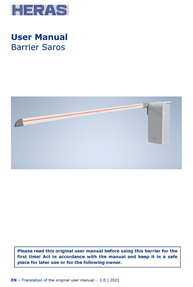
Heras 94 Series User manual

EN –Original user manual - 1.1 | 2022
User manual
Heras Crash Tested Barrier 94x Series
Please read this original user manual before using this barrier for
the first time. Act in accordance with the manual and keep it in a
safe place for later use or for the following owner.

EN –Original user manual - 1.1 | 2022
2

EN –Original user manual - 1.1 | 2022
3
CONTENTS
FOREWORD ............................................................................................................ 5
GENERAL .......................................................................................................... 6
MANUFACTURER /SUPPLIER ........................................................................... 6
1.2 SERVICE /MAINTENANCE................................................................................ 6
1.3 DEFINITIONS USER /OPERATOR /ENGINEER ...................................................... 6
1.4 PRESCIBED USE /APPLICATION........................................................................ 6
1.5CONFORMITY................................................................................................ 7
1.6 DELIVERY..................................................................................................... 7
1.7 ELECTRICAL CONNECTIONS............................................................................ 8
1.8 DELIVERY OF BARRIER ................................................................................... 8
2SAFETY............................................................................................................. 8
2.1 EXPLANATION OF THE SYMBOLS ...................................................................... 8
2.2 GENERAL SAFETY INSTRUCTIONS .................................................................... 9
2.3 SAFETY PROVISIONS.................................................................................... 10
2.4 INTENDED USE............................................................................................ 10
2.5 SAFETY DURING USE.................................................................................... 10
2.6 SAFETY DURING INSTALLATION, MAINTENANCE AND DISASSEMBLY ..................... 11
3OPERATION.................................................................................................... 11
3.1 OPENING /CLOSING BARRIER -NORMAL USE.................................................... 11
3.1 OPEN /CLOSE BARRIER MANUAL RELEASE ...................................................... 12
3.1.1 Barrier manual release .............................................................................. 12
4DESCRIPTION ................................................................................................ 14
4.1 94X SERIES................................................................................................. 14
4.2 LOOP DETECTION........................................................................................ 14
4.3 LASER SCANNER......................................................................................... 14
4.4 ACCESSORIES ............................................................................................ 15
4.4.1 Traffic lights (Optional) .............................................................................. 15
4.4.2 Flash light / beacon (Optional*) .................................................................... 15
4.4.3 Temperature kits (Optional) ........................................................................ 15
4.5 OPERATING MODES ..................................................................................... 15
4.5.1 Hold-to-run mode..................................................................................... 16
4.5.2 Automatic mode ...................................................................................... 16
5CONTROL UNIT............................................................................................... 17
5.1 TOTAL VIEW OF CONTROL PANEL ................................................................... 17
6COMMISSIONING ........................................................................................... 18
6.1 SELECTING CONTROL LOGICS ....................................................................... 18
6.1.1Automatic logic ....................................................................................... 19
6.1.2 Hold-to-run logic...................................................................................... 19

EN –Original user manual - 1.1 | 2022
4
6.2 AUTO-CLOSE TIMER..................................................................................... 20
6.3 ELECTRICAL LIMITS...................................................................................... 20
6.4 MECHANICAL LIMITS .................................................................................... 21
6.5 PRESSURE SETTING .................................................................................... 22
7EMERGENCY STOP .......................................................................................... 23
8MAINTENANCE ............................................................................................... 24
8.1 BARRIER MAINTENANCE ............................................................................... 24
8.2 CLEANING .................................................................................................. 26
9DECOMMISIONING AND REMOVAL ................................................................. 26
10 SPARE PARTS .............................................................................................. 26
11 TECHNICAL DATA ........................................................................................ 27
11.1 DIMENSIONS CABINET............................................................................... 27
11.2 OPERATING CONDITIONS AND SPECIFICATIONS............................................. 27
11.3 OPERATING TIME...................................................................................... 28
11.4 ELECTRICAL INFORMATION ........................................................................ 28
APPENDIX A: DECLARATIONS DOP / DOC ............................................................ 29
APPENDIX B: WIRING DIAGRAM ......................................................................... 37

EN –Original user manual - 1.1 | 2022
5
FOREWORD
This manual provides information on the operation and maintenance of the 94x
range of barriers. A separate manual is provided for installation. Although every
effort has been made to ensure that the information contained within this manual is
correct at the time of issue, no responsibility is accepted for any loss or damage
arising from incorrect information.
This manual forms no part whatsoever of any contract or agreement between He-
ras and others. In no circumstances will Heras be responsible or liable for any
costs, damage or injury whatsoever arising from the use of this Manual.
Should the barrier be tampered with and/or any non-approved equipment be fitted
to the barrier then any warranty will be considered void.
The Copyright of this Manual remains the property of Heras at all times. This Man-
ual may not be reproduced by any means without prior written permission from
Heras.

EN –Original user manual - 1.1 | 2022
6
GENERAL
MANUFACTURER / SUPPLIER
Manufacturer: Heras UK
Herons Way
DN4 8WA Doncaster
Tel.: +44(0) 1302 364 551
www.heras.com
Technical construction file: Manager Heras B.V. PD Department
1.2 SERVICE / MAINTENANCE
In the event of problems, failures or questions telephone contacts are as follows:
Heras Netherlands
Telephone
+31(0) 499 551 255
Heras Germany
Telephone
+49 (0)1805 437277
Heras UK
Telephone
+44(0) 1302 364 551
Heras France
Telephone
+33(0) 3 88 067 000
Heras Norway
Telephone
+47(-) 22 900 555
Heras Sweden
Telephone
+46(0) 77 1506050
1.3 DEFINITIONS USER / OPERATOR / ENGINEER
User: Anyone using the barrier.
Operator: A user who is familiar with all safety aspects dealt with in this manual.
Operators are not allowed to carry out any installation work on the
barrier unless explicitly specified.
Engineer: The engineer is a Heras fitter (or an engineer employed by the cus-
tomer who has been given explicit permission in writing from Heras)
who is qualified to perform technical interventions on the barrier.
1.4 PRESCIBED USE / APPLICATION
Only the correct installation and maintenance by an authorized/qualified company
or person in agreement with the user manual, logbook, check lists and mainte-
nance lists can ensure the safe operation of the system.

EN –Original user manual - 1.1 | 2022
7
A qualified person is, according to EN 12635, a person who has the required train-
ing, qualified knowledge and practical experience required to install, test and main-
tain a barrier system correctly and safely.
1.5 CONFORMITY
The installation complies with the following EU Directives/ regulations:
EU
2006/42/
EC
Machinerichtlijn
EU
2014/30
EU
EMC richtlijn (elektromagnetische compatibiliteit)
EU
305/2011
EC
Verordening bouwproducten (CPR)
UK
Supply of Machinery (Safety) Regulations 2008
UK
Electromagnetic Compatibility Regulations 2016
UK
Construction Products Regulations 2013
The design and production have been executed compliant with the applicable prod-
uct standard EN 13241 and EN 12453.
A Declaration of Performance (DoP) and Declaration of Conformity (DoC) are oblig-
atory for this product. The DoP and DoC are included in Appendix A.
The CE or UKCA mark is located on the cabinet of the barrier.
1.6 DELIVERY
The barrier, drive and control unit must be installed by a fitter or an engineer who
also connects and programs any accessories. The barrier control unit is adjusted to
the options/accessories agreed with the user. The relevant options are laid down
during hand-over.
Optional accessories can be installed afterwards, simply contact the supplier.
Barriers are always delivered fully tested.

EN –Original user manual - 1.1 | 2022
8
1.7 ELECTRICAL CONNECTIONS
Electrical connections must be made compliant with the supplied wiring diagram.
The system must be correctly earthed (Protective grounding in accordance with
DIN VDE).
Because EMC-related suppression components can leak current to the earth cable,
it is advisable that you do not protect the control unit with a Residual Current De-
vice. When switching on the system, a high starting current can be generated due
to the charging of the intermediate circuit.
If after measurement during commissioning it appears that the leakage current ex-
ceeds the permitted 3.5 mA, an additional grounding, in accordance with EN
60335-1 and IEC 30364-5-54, must be provided. Measurement is made according
to EN 60335-2-103. Consult your installer for this.
Take into account good shielding, for example an automatic circuit breaker 16A B
characteristic.
Ensure that the feeder cables are not carrying power during commissioning.
1.8 DELIVERY OF BARRIER
After installation and commissioning, by a Heras technician or a technician trained
by Heras, the cover of the barrier must be closed and locked. This is done to pre-
vent unauthorised access.
2SAFETY
2.1 EXPLANATION OF THE SYMBOLS
Caution! To prevent personal injury, observe the safety instructions
below.
Note! To prevent material damage, observe the safety instruc-
tion below.

EN –Original user manual - 1.1 | 2022
9
Information:Followed by further information or a reference to other
documents.
Warning: Risk of limbs getting crushed.
2.2 GENERAL SAFETY INSTRUCTIONS
•The operator must read the entire user manual before the barrier is used for
the first time. The instructions stated in the user manual must be observed
and complied with. All other forms of use can cause unexpected hazards and
are forbidden.
•Applying a third-party drive unit, motor and/or safety devices may affect
safety and will invalidate the CE mark.
•The barrier must only be put into use if all safety facilities are in place and
connected, and work properly.
•All faults which might present a source of danger to the user or to third per-
sons must be eliminated immediately.
•All warnings and safety notices on the equipment must be in place and clear-
ly legible at all times.
•It is not permitted to mount items to the barrier arm and / or housing other
than as prescribed by Heras. Think of traffic and other signs and such. This
can negatively affect the safe operation of the barrier.
•All alterations or extensions to the barrier must be carried out by qualified
personnel using parts which the manufacturer has defined as suitable for
such alterations or extensions. Any failure to comply with these instructions
will be considered as non-compliant behavior and will invalidate the manu-
facturer's guarantee, as a result of which the risk entirely transfers to the
user.
•Improper usage or servicing or ignoring the operating instructions can be a
source of danger for persons, and/or result in material damage.
•If the meaning of any part of these installation and operating instructions is
not clear, then please contact your supplier before you use the equipment.
•This manual must always be available at the location of use of the barrier.
This manual must be thoroughly read and applied by all persons responsible
for the operation, maintenance and repair of the barrier.

EN –Original user manual - 1.1 | 2022
10
2.3 SAFETY PROVISIONS
•To protect people and goods from injury or damage, the barrier is fitted with
safety provisions including safety loops and/or a laser scanner.
These serve as emergency provisions that immediately stop (and reverse)
the movement of the barrier. It is forbidden to use these provisions to stop
the barrier normally.
•For a barrier with hold-to-run control, the above-mentioned safety provisions
are not necessary and will therefore not be standard provisions.
With this type of operation, the barrier stops immediately as soon as the
switch is released.
2.4 INTENDED USE
Giving safe access for goods and vehicles accompanied or driven by persons in in-
dustrial, commercial or residential premises.
2.5 SAFETY DURING USE
Children or people with a disability must not operate the barrier. Parents
must supervise their children to prevent them playing with the barrier.
➔PARENTS ARE RESPONSIBLE FOR THEIR CHILDREN
•Keep a safe distance from the moving barrier. Warning icons to this effect
•have been installed in various locations
•Only pass through the barrier when it is completely open.
•The barrier must not be opened in windy conditions; wind force >12 Beau-
fort. The barrier arm can swing in a way that can result in damage to the
construction.
•When hold-to-run-control is employed, the barrier must only be operated if it
can be seen completely, directly and in real-time. Operation must be via a
permanently installed operating device, for instance a key switch or push
button. This operating device must be located in such a way that the opera-
tor’s position is safe. The barrier must stop immediately when the button or
key is released.
Other operating devices are not allowed.
•The barrier must be able to move freely without obstacles in the passage and
entire area where the barrier can move. Do not insert objects above or under
the barrier arm that could block the barrier arm.
•The barrier arm must always be free from snow, ice or dirt that might affect
its behaviour. In the event of frost, check this before commissioning the bar-

EN –Original user manual - 1.1 | 2022
11
rier. If the barrier arm is blocked, the barrier will not move at all or will not
complete its movement. Irregularities can damage the drive and / or trans-
mission.
•Climbing the barrier is strictly forbidden as people climbing the barrier could
get hurt if the barrier is started unexpectedly.
•Do not place any obstacles in the opening.
•Always lock the drive unit cabinet during use.
2.6 SAFETY DURING INSTALLATION, MAINTENANCE AND DISASSEMBLY
•When work is carried out or while cleaning the barrier, the power supply to
the system must be switched off and it must be ensured that it cannot be
switched on unexpectedly.
•To move the barrier manually, first switch the automatic fuse in the cabinet
to “off” and make sure it cannot be switched on again (e.g. by locking the
cabinet).
•The barrier is driven by means of a lever construction. This is located in the
cabinet. Beware of moving parts when carrying out maintenance in and near
the barrier cabinet.
•The EN 12453 and EN 13241 standard must be taken into consideration dur-
ing installation and maintenance. To achieve a good safety level, the above
standard and the national regulations must be taken into account in non-EC
countries.
•If the barrier is damaged, always contact the supplier for an inspection.
3OPERATION
3.1 OPENING / CLOSING BARRIER - NORMAL USE
The barrier can be operated using pulse operation, for instance via a button or key
switch. The location of the operating device depends on the customer's choice or
the operating mode.
•OPEN:
Press the “Open” button. The barrier opens to the next end position (85˚).
•CLOSE:
Press the "Close" button. The barrier closes completely.

EN –Original user manual - 1.1 | 2022
12
•STOP:
Press the "Stop" button. The barrier will stop immediately, irrespective of its
direction of travel. To restart the barrier press
“Open” or "Close".
3.1 OPEN / CLOSE BARRIER MANUAL RELEASE
In case of an emergency, the barrier can also be opened or closed manually. To do
this the cabinet must be opened.
Never attempt to raise/lower the barrier by pushing the barrier arm. This can
cause severe damage. Ensure whenever lowering the barrier that the area beneath
is free from people or any other obstacle.
3.1.1 Barrier manual release
•Unlock the cabinet via the locks on the back
•Lift the cover away from the cabinet
•Switch off the mains power, switch is located on the right hand site of the
cabinet
•Turn either raise/lower nipple fully clockwise depending on desired direction
of travel

EN –Original user manual - 1.1 | 2022
13
Figure 1: Manual release
•Locate the hand pump handle, which is stored below the door, into the hand
pump receptor
•Apply lateral movements to the pump handle. It takes a few movements to
begin raising or lowering as pressure builds
Ensure the nipple is released before powering up again. To release, turn it
counterclockwise.
hand pump handle
lower nipple
raise nipple
hand pump receptor

EN –Original user manual - 1.1 | 2022
14
4DESCRIPTION
4.1 94X SERIES
The Heras 94x series is a range of impact tested dual beam vehicle barriers used to
control vehicular access to any kind of high security controlled areas.
The dual beams integrated with the unique fibre system provide formidable me-
chanical characteristics and greater energy absorption on impact than a conven-
tional barrier system. The barrier is applicable for perimeter and interior site use
and can operate both indoors and outdoors. Various beam lengths are available
from up to 6 meters clear opening.
Figure 2: 94X barrier terms
4.2 LOOP DETECTION
A detection loop is an induction loop embedded in the road surface that, with the
assistance of electronics, can detect a vehicle. When the loop detects a vehicle, the
barrier will open and/or stay open. Detection loops do not detect people.
4.3 LASER SCANNER
A laser scanner is a motion and presence related detection device intended for de-
tecting objects in the detection zone. The laser scanner must read in a reference
point as part of the installation process. The barrier will no longer close without a
reference point. The laser scanner will ensure that the barrier does not close, or
stops during closing if an object is in the field.

EN –Original user manual - 1.1 | 2022
15
The laser scanner can also be set so that the barrier opens when a vehicle ap-
proaches.
4.4 ACCESSORIES
4.4.1 Traffic lights (Optional)
Red/green signal lights that indicate the open/closed position statuses. People are
only allowed to pass through the barrier opening when the green light is on.
4.4.2 Flash light / beacon (Optional*)
A flashing beacon to ensure extra attention before and while the barrier is open-
ing/closing.
* In some countries, a flash light is obligatory.
4.4.3 Temperature kits (Optional)
In climates with extreme temperatures, the addition of a heater and/or cooler kit
will be necessary to ensure the motor functions optimally. If temperatures regularly
fall below 0°C, a low temperature modification kit may be required. If temperatures
regularly exceed 40°C, a high temperature modification kit may be required.
Systems operating in such temperatures without the recommended temperature
kits may have operational issues.
4.5 OPERATING MODES
The control software is available to users in two possible operating modes:
•hold-to-run mode
•automatic mode

EN –Original user manual - 1.1 | 2022
16
4.5.1 Hold-to-run mode
The barrier drive can be operated in hold-to-run operating mode with limited com-
fort. In hold-to-run operating mode, the barrier does not require safety features.
The barrier will move as long as an OPEN or CLOSE key is pressed.
It shall only be possible to operate the manual actuators in such a position
that allows full, direct and permanent real-time view of the barrier during the
barrier movement and ensures that the person controlling the barrier is not in a
hazardous position. No controls other than manual actuators are to be installed.
The barrier shall stop when the manual actuators is released.
4.5.2 Automatic mode
If the safety facilities have been installed completely, the motor drive will usually
work in this automatic mode. The user can only use all barrier functions in auto-
matic mode. Total safety of the barrier is guaranteed here by the activated safety
facilities.
Opening or closing the barrier can be initiated in automatic mode by means of:
•hold-to-run buttons OPEN and CLOSE
•impulse buttons OPEN, STOP and CLOSE
Every movement command causes the full action that has been selected to be per-
formed (open barrier, close barrier etc.). Every action is stopped immediately by a
stop command or a signal from the safety facilities.

EN –Original user manual - 1.1 | 2022
17
5CONTROL UNIT
5.1 TOTAL VIEW OF CONTROL PANEL
The control panel for the barrier incorporates a PLC, a switch-mode power supply
unit and a set of field termination connectors/terminals.
Figure 3: View of control panel
free exit
loop
safety loop
field termi-
nals
field termi-
nals
switch-
mode PSU
inverter motor
speed controller
PLC control-
ler

EN –Original user manual - 1.1 | 2022
18
6COMMISSIONING
In this chapter we discuss commissioning the 94X barrier.
6.1 SELECTING CONTROL LOGICS
To select logic simply turn the two potentiometers to the relevant positions as
shown below:
Figure 4: PLC
Automatic Logic
Turn top potentiometer fully clockwise and bottom potentiometer fully counter-
clockwise.
Hold to Run(Open/Raise and Close/Lower)
Turn top potentiometer fully counter-clockwise and bottom potentiometer fully
clockwise.
potentiome-
ters
com port

EN –Original user manual - 1.1 | 2022
19
6.1.1 Automatic logic
Inputs
Stop button
Open
Close
Laser scan-
ner/loop
Open loop
(F exit)
Auto close
timer
Closed
No effect
Opens
No effect
No effect
Opens
Inactive
Closing
Stops
Stops and
reopens
No effect
Stops until
cleared
Stops and
reopens
Inactive
Open
No effect
No effect
Closes
Closes once
clear
Closes once
clear
Closes after 5-
30 seconds
(adjustable)
Opening
Stops
No effect
No effect
Closes once
clear and
fully open
Closes once
clear and
fully open
Inactive
Mid
position
No effect
Open
Closes
No effect
Opens
Inactive
6.1.2 Hold-to-run logic
Inputs
Stop button
Open
Close
Laser scan-
ner/loop
Open loop
(F exit)
Auto close
timer
Closed
No effect
Opens
No effect
No effect
Opens
Inactive
Closing
Stops
Stops and
reopens
No effect
Stops until
cleared
Stops and
reopens
Inactive
Open
No effect
No effect
Closes
No effect
No effect
Inactive
Opening
Stops
No effect
No effect
No effect
No effect
Inactive
Mid
position
No effect
Open
Closes
No effect
Opens
Inactive

EN –Original user manual - 1.1 | 2022
20
6.2 AUTO-CLOSE TIMER
When the barrier system is set to ‘automatic logic’ and an open signal is received
from either a push button or card reader the barrier will open, should no vehicle
drive through the barrier then the barrier arm will re-close after a set time.
Adjusting this timer is done by turning the bottom potentiometer. See Figure 4:
6.3 ELECTRICAL LIMITS
The travel of the barrier is governed by 4 proximity switches and can be adjusted
by loosening the lock nuts.
The proximity switches have a maximum read range of 4 mm and a mini-
mum read range of 2 mm. Stay within this range and make sure the lock
nuts are correct and tight
The open angle must not exceed 85˚ as illustrated on the drawing. The
slowdown activation position, is 15˚ short of full travel as shown on the
drawing. 15˚ measurement is for both up and down positions.
Other manuals for 94 Series
1
Table of contents
Other Heras Control System manuals