Aurora PVI-AEC-EVO User manual

aroruA-3.0.veR
BCB.00029.5
®is a trademark by Power-One - Product is subject to technical improvements
www.power-one.com
QUICK INSTALLATION GUIDE
Aurora®Power Service USA 877-261-1374
Aurora®Power Service France 00 800 00 28 76 72
Aurora®Power Service Germany 0800-2200211
Aurora®Power Service Italy 00 800 00 28 76 72
Aurora®Power Service Spain 00 800 00 28 76 72
Aurora®Power Service Middle East 00 800 00 28 76 72
Aurora®Power Service Australia +61 2 9735 3111
Aurora®Power Service China +86 755 2988 5888
Aurora®Power Service Singapore +65 6896 3363
Aurora®Power Service Malaysia +603-8025 9963
Model:
PVI-AEC-EVO
PVI-AEC-EVO-LIGHT

PVI-AEC-EVO
PVI-AEC-EVO LIGHT
Monitoring System
Note: Any changes / modification not approved by the responsible party could void the
user authority to operate the equipment.
12-07-2013REV. 3.0
Note: This document contains proprietary information of Power-One, Inc.
The contents of this document or any part thereof should not be reproduced or disclosed
to any third party whitout Power-One’s express written consent.
BCB.00029.5
QUICK INSTALLATION GUIDE
- USER MANUAL -
This manual contains important safety instruction that must be followed during the
installation and start-up of the device. It’s recommended to give special attention to the
installation instruction in order to reduce the risks pf electric shock and prevent damage
to the device.
SAVE THESE DOCUMENT IN A SAFE PLACE!
IMPORTANT SAFETY INSTRUCTION!

1-EN
CONTENTS
H. Configuration of the Analog Inputs 11
D. Pin-Outs of System Connectors 5
E. Power Supply Connections and System Start Up 6
F. Date andTime Settings 7
G. Connection of the RS485 Line and Inverter Acquisition Check 7
C. 4
User Interface and Use of the Display
B. Package Content 3
System Configuration for Connection to the LAN Network (Ethernet Port)
I. 14
Appendices
1) Sensor Connection Diagrams
2) RS485 Cable Features
3) Display flow-charts
4) Compliance Requirements
PVI-AEC-EVO / PVI-AEC-EVO LIGHT
QUICK INSTALLATION GUIDE
A. Prod
The PVI-AEC-EVO i
products. Inthe fol
thecharacteristicso
The product allows
centralinvertermo
The system is equip
or 62 55kW conve
communication po
withModbus comm
The system is equip
parameters: Power-
andwinddirection.
The system also has
areassociatedwiths
With respect to the
integratedwebserv
The initial system c
network parameter
detailed parameters
toaccessthepageso
ThePVI-AEC-EVOwo
abletocarryoutmo
ThewebportalAuro
Note: For PV
becon
PVI-2
PVI-3.
In the
param
PVI-1
(*): Com
21
Firmware UpdatingN.
L. Internal Webserver access 17
20
Mac Address IdentificationM.
A. Product Description 2

11
5
6
7
7
4
3
rt) 14
Monitoring System
2-EN
A. Product Description
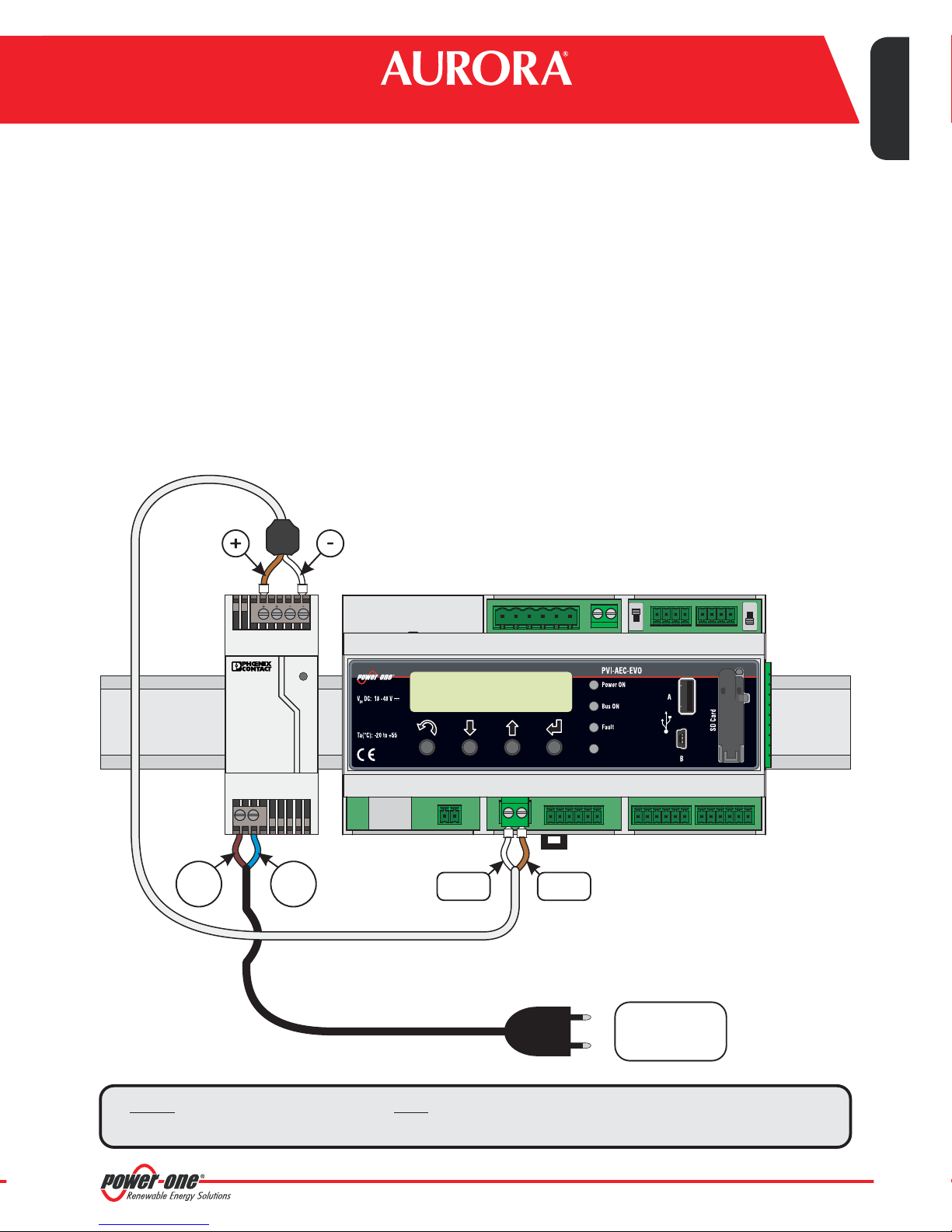
The PVI-AEC-EVO is a monitoring and checking system for photovoltaic systems made with Power-One Aurora
products. Inthe following pages we will make reference to the“system”meaning both versions of the product.Whereas
thecharacteristicsofproductaredifferent willbespecified.
The product allows to acquire parameters from the inverter and string-comb (in accordance with the design of the
centralinvertermonitoringsystem)throughthe RS485 linewith thePower-Oneproprietaryprotocol.
The system is equipped with two equivalent RS485 ports and each of them allows a maximum of 62 string inverters
or 62 55kW conversion modules (centralized modular inverters) to be acquired; It is also possible to use the
communication port RS485/1 (Ref.Par.D) to acquire parameters from power meters equipped
withModbus communicationinterface.
themodel
“ISKRAMECOMT831”
EN - ENGLISH
The system is equipped with three analog inputs for the connection of sensors for the measurement of environmental
parameters: Power-Oneoffersin its cataloguea completerangeofradiation sensor,cell and ambienttemperature,speed
andwinddirection.
The system also has six digital inputs for acquiring state signals (for example auxiliary contacts of power switches) which
areassociatedwithstatealarmconditions.
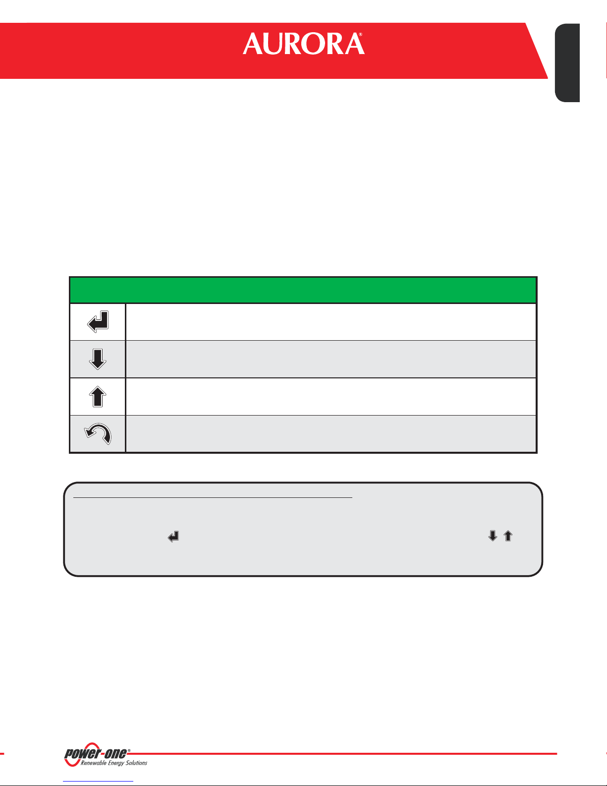
With respect to the user interface, the system is equipped with a 2x16 character display and four keys as well as an
integratedwebserverwithhtmlpageswhichareaccessiblethroughLANconnection.
The initial system configuration (check that the inverter parameters are acquired, analog inputs configuration, LAN
network parameters configuration) can be carried out completely through the display and keys; for displaying the
detailed parameters of the inverters and/or of the string-combs,as well as for the advanced configurations it is necessary
toaccessthepagesoftheintegratedwebserver.
ThePVI-AEC-EVOworksin conjunctionwiththeservicewebportalAuroraVision:byregisteringforthisserviceyouwill be
abletocarryoutmonitoringandremotemanagementofsystemsassociatedwithyouraccount.
ThewebportalAuroraVisionisavailableonthewebsite: www.Auroravision.net
Note: For PVI-AEC-EVO LIGHT,the max number of string inverter manageable by the system is 5,which can
beconnectedonlybyRS485/2(Ref.Par.D).Onlythefollowings(inalloftheirvariants)areallowed:
**
PVI-2000(-OUTD) UNO-2.0/2.5-I-OUTD PVI-3600
PVI-3.0/3.6/4.2-TL-OUTD PVI-3.8/4.6-I-OUTD PVI-5000/6000-TL-OUTD
*
In the PVI-AEC-EVO LIGHT the communication port RS485/1 (Ref. Par. D) can be used only to acquire
parametersfrom“ISKRAMECOMT831”powermetersequippedwithModbuscommunicationinterface.
PVI-10.0/12.5-TL-OUTD PVI-10.0/12.0-I-OUTD
(*): Compatibilityisalsoextendedtopreviousnationalversions(Ex:PVI-3.6-OUTD-UK)
21
17
20
2

C. User
Thesystemfeatures
Usingthe displayan
ofparameteracquis
For displaying the
configurationsitisn
Alistoffunctionsac
Accesstothe m
Toperformtheini
Press the 'ENTER'
change the value
menusofthesyste
'Ent
the
'Do
des
'Up
ord
'Esc
3-EN
B. Package content
Note: Checkthepackagecontentcorrespondstotheabovelist.
Pleasechecktheboxandeachsingleiteminsidehasnodefect.Incaseclaimstotheshippingcompany
andcommunicates quicklytotheassistanttechnicalserviceortotheCustomerserviceofPower-One.
1
2
3
AURORA PVI-AEC-EVO / PVI-AEC-EVO LIGHT
Power Supply 100-240Vac 50-60Hz / 24Vdc
Quick Installation Guide
Power Supply connection cable
SD Card (assembled)
I/O Terminal Blocks Counterparts (assembled)
RS485 Terminal Blocks Counterparts (assembled)
Relais Terminal Blocks Counterparts (assembled)
Power supply Terminal Blocks Counterparts
(assembled)
4
5
6
7
8
9
DC
OK
STEP POWER
L(+) N(-)
Input AC
100-240V
--++
Output DC
24V 0.75A
1 2 4
5 6 7 8 9
3
PVI-AEC-EVO / PVI-AEC-EVO LIGHT
QUICK INSTALLATION GUIDE

4-EN
C. User interface and use of the display
Thesystemfeaturesa2x16characterdisplay,fourbuttonsfornavigatingmenus,andthreeLEDstoindicatedevicestatus.
Usingthe displayandthe buttons on thefrontpanelit ispossible to perform the initialconfigurationofthe system (check
ofparameteracquisitionfrominverter,analoginputconfiguration,andconfigurationofLANnetworkparameters).
For displaying the detailed parameters of the inverters and/or of the string-combs, as well as for the advanced
configurationsitisnecessarytoaccesstheinternalwebserverfollowingtheproceduredescribedinparagraph“L”.
AlistoffunctionsaccessiblefromthedisplayisshowninthetableinAppendix3.
Accesstothe mainmenu withadministratorprivileges
Toperformtheinitialconfigurationitisnecessarytoaccessthevariousdisplaymenusasadministrator.
Press the 'ENTER' key ( ) and insert password : To insert the password press the arrow keys ( ) to
change the value and the 'ENTER' key to confirm the value. This password gives access to all the display setting sub-
menusofthesystem.
0010
'Enter' button. Used to confirm an action,to access the main menu or the sub-menu corresponding to
theselectedentry(indicatedbythe>symbol),ortogotothenextdigittochange.
'Down' button. Used to scroll down through the menu items, or to scroll the numerical scale in
descendingorder.
'Up' button. Used to scroll up through the menu items,or to scroll the numerical scale in ascending
order.
'Esc'button. Usedtoreturntothepreviousmenuortoreturntothepreviousdigittochange.
USE OF BUTTONS
ippingcompany
ceofPower-One.
4
8 9
Monitoring System
EN - ENGLISH

E. Powe
1. Connect the p
supply will ligh
supplyfromth
2. Connect the ou
polarity and us
3. Connect the po
during which t
The message“
bedisplayed.
5-EN
D. Pin-Out of System Connectors
Thediagrambelowshowsthepin-outoftheconnectorswhichallowthesystemconnection.
L(+)
PVI-AEC-EVO / PVI-AEC-EVO LIGHT
QUICK INSTALLATION GUIDE
*In the PVI-AEC-EVO LIGHT model the RS458/1 port (J17) is not available as inverter communication port,but can be used only to
acquireparametersfrom powermetersequippedwithModbuscommunicationinterface.ISKRAEMECO
Note: The sy
confo
J18
BATTERY IN
1) + Batt.
2) - Batt.
J7
LAN
IEEE802.3u
J8
Vin DC
1) + Vcc
2) - Vcc
J3
ANALOG INPUT
PT100/1000
1) PT_ALIM
2) PT_SENSE
3) PT_RTN
4) AIn_RTN
5) AIn 1
6) AIn 2
J20
DIGITAL I/O
1) DO_RTN_PWM1
2) DO_ _PWM2
3) DO_PWM 1
4) DO_PWM 2
5) DIn 1
6) DIn_RTN
RTN
J4
DIGITAL I/O
1) DIn 2
2) DIn 3
3) DIn 4
4) DIn_RTN
5) DIn 5 / CONT 2
6) DIn 6 / CONT 1
11122
3456123456 1234562
123456 12
3
41234
J12
GROUND
J17
RS485/1
1) RTN
2) - T/R
3) +T/R
4) +5V
*
J5
RELAY
1) RELAY1-C
2) RELAY 1 - N.O
3)
4)
5)
6)
RELAY2-C
RELAY 2 - N.O
RELAY3-C
RELAY 3 - N.O
J15
RS485/2
1) RTN
2) - T/R
3) +T/R
4) +5V
S2
120
RS485/1
ΩTERM.
S1
120
RS485/2
ΩTERM.
J9
EXPANSION
BUS
NOTE:
Only for dedicated
accessory
PVI-BATTERY-PACK
INPUT DC:
24 Vdc
0,3 A
(max. 48 Vdc)
NOTE:
Use the provided
power supply

6-EN
E. Power Supply Connections and System Start Up
1. Connect the power supply to the power supply network (100/240V 50/60Hz): the "Power" led on the power
supply will light up steadily.Check that the output voltage of the power supply is 24Vdc.Disconnect the power
supplyfromthepowersupplynetwork.
2. Connect the output of the power supply to the power supply terminal block of the PVI-AEC-EVO respecting the
polarity and usingthewiring provided.
3. Connect the power supply to the power supply network:After a first starting phase (lasting about 30 seconds)
during which the system is not able to receive any input from the user,the green "PowerOn" led will remain lit.
The message“PVI-AEC-EVO...." (in the first of the two lines) and date/time (in the second of the two lines) will
bedisplayed.
DC
OK
STEP POWER
L(+) N(-)
Input AC
100-240V
--++
Output DC
24V 0.75A
+Vcc-Vcc
L(+) N(-)
50-60 Hz
100-240 V~
12
Monitoring System
EN - ENGLISH
can be used only to Note: The system must be supplied with power supply and wiring provided; otherwise the CE
conformitywillnotbelongervalid.
ONLY
4
GITAL I/O
DIn 2
DIn 3
DIn 4
DIn_RTN
DIn 5 / CONT 2
DIn 6 / CONT 1
S1
120
RS485/2
ΩTERM.
J9
EXPANSION
BUS

Note: The m
conne
than6
them
In the
string
variat
PVI-3.
PVI-1
Note: When
towir
Thela
the12
string
Note: In cas
RS485
Note: For fu
resist
Note: All str
contin
For si
indica
7-EN
F. Date and time settings
1. Enterthemain menu asadministrator(Seepar.'C’).
2. Access the menu and then select the sub-menu. This enables to set the
correctdateinthe system.
3. Return to the menu and then select the sub-menu. This enables to set the correct time
inthe system.
'SETTINGS' > 'DATALOGGER' 'SET DATE'
'DATALOGGER' 'SET TIME'
>datalogger
io settings
>settings
change password ENTER ENTER
PVI-AEC-EVO ......
12.00.00 01/01/11
menu pin
0***
ENTER ENTER
>set date
set time
>set date
01/01/11
ENTER ENTER
>set time
network
>set time
12.00.00
ENTER ENTER
CHANGE VALUE NEXT
FIELD
CHANGE VALUE NEXT
FIELD
CHANGE VALUE NEXT
DIGIT
SET PIN TO 0010
G. Connection of the RS485 line and inverter acquisition
check
Theconnectionof the RS485linemust be carriedout respectingthepin-outs ofthe J15and/or J17connectors.
I
t is recommended to connect the RS485 line when all the equipment is switched off (both the monitoring system
andthe inverters)and tostart up themonitoringsystemfirstand then theinverters. Itis recommendedto:
Use a cable for RS485 applications with the following characteristics: 1 twisted pair+1conductor or two
twisted pairs,Screen and characteristic Impedance equal to 120 . For further information on the cable to be
usedrefertoAppendix2.
Makesurethe signalscorrespond.
Makesurethat allthreelines (+T/R,-T/R andRTN) are connectedaccordingtothe diagramsin pages9-10.
Make sure that each element in the chain (each inverter or each 55kW module) has a RS485 address that is
differentfromthe others.Thisaddress can besetvia the displayof the inverter.
Ω
l
l
l
l
l
Makesurethat thecommunicationline screen is groundedaccordingtothediagrams in pages9- 10).
Note: For PVI-AEC-EVO LIGHT, the only usable RS485 port for inverter monitoring is the RS485/2,
correspondenttoconnectorJ15.
Note: For P
addre
PVI-AEC-EVO / PVI-AEC-EVO LIGHT
QUICK INSTALLATION GUIDE
Note: The ce
with“
line in
theca

8-EN
Note: The maximum number of units (string inverters or/and 55kW conversion modules) that can be
connected to a RS485 port of the PVI-AEC-EVO is 62.In order to connect a number of units greater
than62 itis necessaryto use thesecondRS485/2 port respectingthe samewiring diagramused for
themainRS485/1port.
In the PVI-AEC-EVO LIGHT the number of inverters that can be acquired is limited to a maximum of 5
strings inverters which can be connected by RS485/2 (Ref.Par.D). Compatible models (in every their
variation) for the PVI-ACE-EVO LIGHT version are:PVI-2000(-OUTD); UNO-2.0/2.5-I-OUTD; PVI-3600;
PVI-3.0/3.6/4.2-TL-OUTD; PVI-3.8/4.6-I-OUTD; PVI-5000/6000-TL-OUTD; PVI-10.0/12.5-TL-OUTD;
PVI-10.0/12.0-I-OUTD.
Note: When connecting multiple units (string inverter or/and 55kW conversion modules) it is necessary
towiretheRS485communicationlineaccordingtothedaisy-chaindiagram(enter-exit).
Thelastinverterofthedaisy-chainmustbe'terminated'byactivatingtheterminationresistanceof
the120 communicationlinethroughswitchingthedip-switchlocatedonthe motherboardinthe
stringinverters,and insideeachframeworkofthecentralinverters.
Ω
Note: In case of mixed systems, the presence of both string inverters and central inverters on the same
RS485lineispermitted.Towirethislinefollowallthedirectionsabove.
Note: For further details on the wiring of the RS485 line and/or the activation of the termination
resistances,refertotheusermanualofstringinvertersandtotheusermanualofcentralinverters.
Note: All string inverters (except for models PVI-5000/6000-TL-OUTD) have a clamp that allows giving
continuitytothecableshieldoftheRS485line.
For single-phase inverters this clamp is indicated by the words LNK, for three-phase inverters it is
indicatedbySCLD.
senables to set the
set the correct time
ENTER
ENTER
ENTER
NEXT
FIELD
NEXT
FIELD
NEXT
DIGIT
0010
cquisition
7connectors.
monitoring system
mendedto:
conductor or two
non the cable to be
npages9-10.
485 address that is
es9 - 10).
is the RS485/2,
Note: For PVI-AEC-EVO LIGHT, the inverters must be set with addresses: 1,2, 3,4, 5.The configuration of
address1correspondsto"AUTO"settingsasinverteraddress.
Monitoring System
EN - ENGLISH
Note: The centralized inverters have a clamp, which is located in the signal terminal block and marked
with“X23”, that allows to link to ground the shield of each singular portion of the communication
line independently from the other portion of communication line.(must not be given continuity to
thecableshield).

120 TERM.
RESISTOR
Ω
ON
120 TERM.
RESISTOR
Ω
OFF
120 TERM.
RESISTOR
Ω
OFF
Note: Make sure that each
55 kW module in the chain
has a RS485 address that is
different from the others.
9-EN
AURORA
AURORA
AURORA
+T/R
-T/R
RTN
RS485
120
Ter m .
Resistor
Ω
OFF
ON
+T/R
-T/R
RTN
RS485
120
Ter m .
Resistor
Ω
OFF
ON
+T/R
-T/R
RTN
RS485
120
Ter m .
Resistor
Ω
OFF
ON
-T/R
RTN
+T/R
-T/R
+T/R
RTN
RS485
OFF
ON
RS485
OFF
ON
120 TERM.
RESISTOR
Ω120 TERM.
RESISTOR
Ω
-T/R
+T/R
RTN
RTN +T/R -T/R RTN +T/R -T/R
12
3
41234
120 TERM.
RESISTOR
Ω
ON
120 TERM.
RESISTOR
Ω
OFF
120 TERM.
RESISTOR
Ω
ON
PVI-AEC-EVO / PVI-AEC-EVO LIGHT
QUICK INSTALLATION GUIDE
Note: Make sure that each
inverter in the chain has a RS485
address that is different from the
others. For PVI-AEC-EVO LIGHT,
the inverters must be set with
addresses: 1, 2, 3, 4, 5. The
configuration of address 1
corresponds to "AUTO" settings as
inverteraddress.

10-EN
-T/R
RTN
+T/R
X20 X21 X22 X23 X24 X25 X26 X27
D
A
X20 X21 X22 X23 X24 X25 X26 X27
D
A
RTN +T/R -T/R
X20 X21 X22 X23 X24 X25 X26 X27
D
A
X20 X21 X22 X23 X24 X25 X26 X27
D
A
120 TERM.
RESISTOR
Ω
ON
120 TERM.
RESISTOR
Ω
OFF
120 TERM.
RESISTOR
Ω
OFF
X20 X21 X22 X23 X24 X25 X26 X27
D
A
RTN +T/R -T/R
12
3
41234
120 TERM.
RESISTOR
Ω
ON
Note: Make sure that each
55 kW module in the chain
has a RS485 address that is
different from the others.
RS485 RS485
RTN +T/R -T/R RTN +T/R -T/R
120 TERM.
RESISTOR
Ω
OFF
120 TERM.
RESISTOR
Ω
ON
Monitoring System
EN - ENGLISH

The measurement is
betweenthesetwos
The PT100/PT1000
furthersettings.
Regarding the conn
be taken directly fro
readingisthesame.
For the sensor conn
measuredatoneoft
Thegroundingof th
sensorrangeonlyin
After carrying out t
acquired:
1. Enterthemain
2. Accessthemen
3. Select the
selectedmodel
4. Select the
selectedmodel
“ANA
“ANA
PVI-AEC-E
12.00.00
>ANALOG I
ANALOG I
>settings
change p
>ANALOG I
PULSE IN
Note: Incas
clamp
11-EN
After carrying out these checks, start up first the monitoring system and then the inverters.The system automatically
carries out a scan of the RS485 bus and automatically detects the available inverters.The presence of the inverters can be
checkeddirectlyfromthedisplay.
1. Enterthemainmenuasadministrator(Seepar.'C’).
2. Accessthe menu(todisplaythestring inverters)and/or
(to display the 55kW conversion modules). The number of inverters detected during the scan will be
displayed;thelistofthe monitoredinvertersidentifiedbytheSerialNumber(S/N)canbedisplayedbyscrollingusing
thearrowkeys( ).
'CURRENTVALUES'> 'ENERGY INVERTERS' 'CURRENTVALUES' >
'ENERGY RACK'
H. Configuration of the Analog Inputs
Theconnectionoftheanaloguesensorsmustbecarriedoutrespectingthepin-outsoftheJ3connector.
Thesystemhastwo0-10VdcinputsandaPT100/1000input.
CHANGE VALUE NEXT
DIGIT
SET PIN TO 0010
PVI-AEC-EVO ......
12.00.00 01/01/11
>ENERGY INVERTERS
ENERGY RACK
menu pin
0***
30 INVERTERS
>INVERTER SN 123456
>CURRENT VALUE
SETTINGS
ENTER ENTER
ENTER
ENTER CHANGE
INVERTER
>ENERGY RACK
ENERGY PLANT
RACK N. 1
>RACK SN 123456
ENTER CHANGE
RACK
Note: The time necessary for the PVI-AEC-EVO to scan and acquire the inverters depends on the number of
inverterspresentonthesameline(sometimesseveralminutes).
Note: To each analogueinput (both0-10Vdcand PT100/1000 types)itis possibletoconnect onlyone analog
sensor. Itisthereforenotpossibletoconnectmultiplesensorsonthesameanaloginput.
With respect to the connection of the PT100/1000 sensors,the system is able to carry out the sensor reading through the
connectionofthree-wires:
l
l
l
Asensorpowersupplyline(PT_ALIM);
Areadingline(PT_SENSE);
Apowersupplyandreadingclosingline(PT_RTN).
PVI-AEC-EVO / PVI-AEC-EVO LIGHT
QUICK INSTALLATION GUIDE

12-EN
The measurement is carried out between PT_SENSE and PT_RTN,therefore the element to be measured must be wired
betweenthesetwosignals.
The PT100/PT1000 sensor is automatically recognised by the system and is therefore acquired without the need for
furthersettings.
Regarding the connection of the sensors with output range 0...10Vdc,these must be powered and the power supply can
be taken directly from the system power supply; the grounding of the power supply and the grounding of the signal
readingisthesame.
For the sensor connection,beside the power supply, it is necessary to connect the signal proportionally to the quantity
measuredatoneofthetwoanaloginputsavailable(Aln1/Aln2).
Thegroundingof thesignaltobe measured (if differentfromthegroundingof the powersupply– within thePower-One
sensorrangeonlyinthewindspeedsensorPVI-AEC-WIND-COMPACT)mustbeconnectedtotheAln_RTNclamp.
After carrying out the connections it is necessary to configure the sensor in the system so that the correct quantity is
acquired:
1. Enterthemainmenuasadministrator(Seepar.'C’).
2. Accessthemenu .
3. Select the item and then select the sensor model connected to the AIn1 input of the system (the
selectedmodelwillbeidentifiedwithanasterisk(*)).
4. Select the item and then select the sensor model connected to the AIn2 input of the system (the
selectedmodelwillbeidentifiedwithanasterisk(*)).
'SETTINGS'>'IOSETTINGS'
“ANALOG INPUT1”
“ANALOG INPUT2”
PVI-AEC-EVO ......
12.00.00 01/01/11
>io settings
UPGRADE FIRMWARE
menu pin
0***
>ANALOG INPUT1
ANALOG INPUT2
>settings
change password
ENTER ENTER
ENTER ENTER
ENTER ENTER
>ANALOG INPUT1
T1000-INTEGR *
CHANGE VALUE NEXT
DIGIT
SET PIN TO 0010
CHANGE
SENSORS
>ANALOG INPUT2
PULSE IN1 ENTER ENTER
>ANALOG INPUT2
RAD-13TC * CHANGE
SENSORS
Note: Incaseofconnecting PT100/1000 sensorswithonlytwoterminals,connect aterminaltothe PT_SENSE
clampandaterminaltothePT_RTNclamp,thenmakeajumperbetweenPT_ALIMandPT_SENSE.
ystem automatically
the inverters can be
ring the scan will be
edbyscrollingusing
'CURRENTVALUES'>
or.
NEXT
DIGIT
0010
ENTER
on the number of
tonlyoneanalog
t.
reading through the
Monitoring System
EN - ENGLISH

13-EN
To readthemeasurementsof thesensors andto check theiraccuracy followthe instructions below:
1. Enterthemain menu asadministrator(Seepar.'C’).
2. Access the menu . The quantity value will be displayed for each of the
analoginputs.
'CURRENT VALUES' > 'ANALOG VALUE'
PVI-AEC-EVO ......
12.00.00 01/01/11
>ANALOG VALUE
DIGITAL VALUE
menu pin
0***
>T1000-INTEGR AN1
20.0 DEGC
>CURRENT VALUE
SETTINGS
ENTER ENTER
ENTER ENTER
CHANGE
INPUT
CHANGE VALUE NEXT
DIGIT
SET PIN TO 0010
PVI-AEC-EVO / PVI-AEC-EVO LIGHT
QUICK INSTALLATION GUIDE
Note: In the following table it is reported a list of the sensor which are present in the catalogue“Power-one”.
Fortheconnectionofthesesensors,pleasemakereferencetodiagramsshowninAppendix1.
Note: The system is predisposed for the connection to other sensors available: ZippZonen Pyranometer 0-
1600W/m and
2Pyranometer0-2000W/m .
2
I. System
Netwo
The connection to t
bothdevicestoa lo
Incase ofdirect con
thenetworkparam
Incaseofconnectio
which have to be c
networkadministra
In order to change
: the n
CHANGEOFPCNETW
Connections”
“LocalAreaConnec
Select “Internet Pr
“Properties”.
Note: The IP
theym
The su
MODELL TYPE
PVI-AEC-IRR Radiation sensor (W/m --> V)
2
PVI-AEC-IRR-T Radiation sensor with integrated cell
temperature sensor (W/m --> V)
2/°C
PVI-AEC-T1000-INTEGR
PVI-AEC-T100-ADH
PVI-AEC-T1000-BOX
PVI-AEC-WIND-COMPACT
PVI-AEC-WIND-DIR
PVI-AEC-PYR-1300 Pyranometer ( --> V)W/m2
OPERATIVE
RANGE
0-1200 W/m
2
0-1200 W/m
2
-20 to +80 °C
-50 to +50 °C
-50 to +150 °C
-50 to +50 °C
0-50m/s
0 - 360°
0-1300 W/m
2
PVI-AEC-RAD-13TC
PVI-AEC-RAD-13TC-T
DISPLAY
IDENTIFICATION CODE
IRR
IRR-T_Irr /
IRR-T_Temp
T1000-INTEGR
T100-ADH
T1000-BOX
WIND-COMPACT
WIND-DIR
Pirano_0-20mA
RAD-13TC
RAD-13-TC-T_Irr /
RAD-13-TC-T_Temp
0-1300 W/m
-25 to +90 °C
2
0-1300 W/m
2
SENSORS WITH ANALOG OUTPUTS COMPATIBLE WITH PVI-AEC-EVO (POWER-ONE CATALOGUE)
Radiation sensor (W/m --> V)
2
Radiation sensor with integrated cell
temperature sensor (W/m --> V)
2/°C
Adhesive module temperature sensor
(back cell) PT100
Ambient temperature sensor connected to
PT100/0...10Vdc converter (°C --> V)
Ambient temperature sensor PT100
Wind direction sensor (° --> V)
Wind speed sensor (m/s --> V)

14-EN
w:
yed for each of the
ENTER
NEXT
DIGIT
0010
Monitoring System
EN - ENGLISH
gue“Power-one”.
endix1.
Pyranometer 0-
I. System Configuration for connection to the LAN
Network (Ethernet Port)
The connection to the PC of PVI-AEC-EVO can be made through direct connection via Ethernet cable,or connecting
bothdevicestoa local networkLAN (viarouter,hubor switch).
Incase ofdirect connection,it isenough toconnectthe twodevicesbetween them throughaEthernet cable andset
thenetworkparametersof PVI-AEC-EVOand ofthe PCtomakesuretheyarecompatiblebetweenthem.
Incaseofconnectiontoapre-existinglocalnetworkLAN,itisnecessarytoassigntoPVI-AEC-EVOthenetworkparameters
which have to be compatible with the local network to which the PVI-AEC-EVO is connected. Make reference to the
networkadministratortoobtainthecorrectparametersofthenetwork.
In order to change pc network parameters, please select and then click on
: the new window will show the network connections; with the right button of your mouse click on
andselect ;as shownin the followingfigure.
CHANGEOFPCNETWORKPARAMETERS
“Start” “Control Panel”, “Network
Connections”
“LocalAreaConnection” “Properties”
Select (or in Windows 7/8) and click on“Internet Protocol (TCP/IP)” “Internet Protocol Version 4 (TCP/IPv4)”
“Properties”.
Note: The IP address of the PC and the IP address of the PVI-AEC-EVO must belong to the same group but
they ,forinstance:
20.200.200.
20.200.200.
mustnotbeidentical
PC IP ADDRESS:
PVI-AEC-EVO IP ADDRESS:
1
24
The subnet mask must be the same for both devices,for instance: 255.0.0.0
Windows XP Windows 7/8
OPERATIVE
RANGE
0-1200 W/m
2
0-1200 W/m
2
-20 to +80 °C
-50 to +50 °C
-50 to +150 °C
-50 to +50 °C
0-50m/s
0 - 360°
0-1300 W/m
2
E
0-1300 W/m
-25 to +90 °C
2
0-1300 W/m
2
CATALOGUE)

CHANGETHEPVI-AE
:inordertochanget
1.
2.
3. Access the me
4. At the end of t
makethesetti
Poweronthes
Enterthemain
Subnet mask,G
systemforcon
PVI-AEC-E
12.00.00
>NETWORK
SET DATA
>settings
change p
>IP metho
ip setti
>IP SETTI
SUBNET M
>SUBNET M
ip gatew
>IP gatew
ip metho
15-EN
PVI-AEC-EVO / PVI-AEC-EVO LIGHT
QUICK INSTALLATION GUIDE
Select the option and insert the network parameters (IP address, Subnet Mask,
Gateway)compatiblewith thenetworkparameterssetin the PVI-AEC-EVO.
DNSparametersfields can beletempty.
“Use the following IP address”
Note: In case of direct connection between PVI-AEC-EVO and PC we suggest not to set “Gateway”
parameters.
Note: Thistypeofprocedureistobeconsideredonlyanexampleforthemostpopularoperatingsystems.

CHANGETHEPVI-AEC-EVONETWORKPARAMETERS
:inordertochangethePVI-AEC-EVOnetworkparameters,please followtheprocedurebelow:
1.
2.
3. Access the menu .
4. At the end of the setting operations, return to the main screen, then switch off and switch on the system to
makethesettings take effect.
Poweron the systemand waitforthe start up phasetocomplete(Ref.Par.'E’).
Enterthemain menu asadministrator(Ref.Par.'C’).
The parameters for connection to the LAN network (IP address,
Subnet mask,Gateway) may be modified using the items of the menu.This allows to configure the
systemforconnection to the LANnetworkand/orfor direct connectiontoa PC.
“SETTINGS” > “NETWORK”
"NETWORK"
PVI-AEC-EVO ......
12.00.00 01/01/11
>datalogger
io settings
>IP method
manual
menu pin
0***
>NETWORK
SET DATA
>settings
change password
>IP method
ip setting
ENTER ENTER
ENTER ENTER
ENTER
ENTER ENTER
CHANGE VALUE NEXT
DIGIT
SET PIN TO 0010
>IP SETTING
XXX.XXX.XXX.XXX
>IP SETTING
SUBNET MASK ENTER ENTER
CHANGE VALUE NEXT
DIGIT
>subnet mask
XXX.XXX.XXX.XXX
>SUBNET MASK
ip gateway ENTER ENTER
CHANGE VALUE NEXT
DIGIT
>IP gateway
XXX.XXX.XXX.XXX
>IP gateway
ip method ENTER ENTER
CHANGE VALUE NEXT
DIGIT
CHANGE
METHOD
16-EN
Monitoring System
EN - ENGLISH
ress, Subnet Mask,
oset “Gateway”
ratingsystems.

Note: To mak
to the
graphi
essent
connec
PVI-AE
Inorder to allowth
(CONFIG) of the ne
thereis theIPaddre
Note: If the
above
(ON-O
17-EN
Latitude
Longitude
Latitude
Longitude
Indicator Degrees Point Degrees (Hundredths of degree)
Degrees Indicator Minutes Quotation Mark Seconds Double quotation mark*
N43.33
E11.35
43N50’20”
11E23’30”
43
11
N
E
50
23
‘
‘
20
30
“
“
N43 . 33
E11. 35
*
The Double Quotation Mark ( ”) symbol must be inserted by entering twice the quotation mark(')symbol.
In order to access to the Webserver pages of the system, after having done the connection of the system to the local
network LAN or direct connection to the PC, open an internet browser (e.g. Internet Explorer) and type into the
addressbar thefollowingaddress:
http://<system IP address>
After having done the access to the internal Webserver, go to the configuration page (CONFIG) of the system
(PLANT) andinserttheinstallationGPS coordinatesaccordingto one ofthefollowingformats:
Note: TosettheGPSparameterismandatorytoassuretheproperworkingofmonitoringsystem.
PVI-AEC-EVO / PVI-AEC-EVO LIGHT
QUICK INSTALLATION GUIDE
L. Internal Webserver access
Note: Toaccessthewebserverpagesitisnecessarytoinsertausernameandapassword:
USERNAME: admin PASSWORD: admin

18-EN
Note: To make the system fully functioning it is essential that the same system is constantly connected
to the internet so that it is able to communicate with the Power-One server. This is essential to
graphically shows the data on web pages as well as for sending alarm and/or report messages.It is
essential that the LAN network in which the PVI-AEC-EVO is wired is such that it allows the
connection to the IP address 63.236.63.180 to be reached through port 80, so that the
PVI-AEC-EVO isabletocommunicatewiththeportalmanagementserver.
Inorder to allowthe PVI-AEC-EVOto communicatewith theAuroraVision webportal,accessthe configurationpage
(CONFIG) of the network (NETWORK) and check that in section 'DATA TRANSFER', under item 'IP Address Portal'
thereis theIPaddress .63.236.63.180
Note: If the setting 'IP Portal Address' does not correspond to 63.236.63.180, change it by entering the
above-mentioned address and press 'Confirm' to activate it.After this operation,reset the system
(ON-OFF).
Monitoring System
EN - ENGLISH
Hundredths of degree)
ouble quotation mark*
“
“
33
35
system to the local
and type into the
FIG) of the system
system.
This manual suits for next models
1
Table of contents
Languages:
Other Aurora Inverter manuals
Popular Inverter manuals by other brands

Samlexpower
Samlexpower SSW-350-12A owner's manual

MULTIQUIP
MULTIQUIP DA7000SSA1 Specifications

Zeversolar
Zeversolar Evershine TLC4000 Installation and operating instructions

Nice
Nice Solemyo SYKCE Installation and use instructions and warnings

Fuji Electric
Fuji Electric FRENIC5000G11S Series Connection manual

Nord Drivesystems
Nord Drivesystems SK 200E Series user manual