Aus3D RUMBA32 V1.1 User manual

RUMBA32 V1.1 User Manual – Rev A Page 1
RUMBA32 V1.1 Reference Manual
Revision A

RUMBA32 V1.1 User Manual – Rev A Page 2
1INTRODUCTION
1.1 OVERVIEW
This is a user/reference manual for the Aus3D RUMBA32 V1.1 3D printer control board.
Sections of this manual may be relevant to other versions of RUMBA32. However, there are some
differences between versions, and may even be differences between boards of the same version when
produced by other manufacturers, so it is recommended to always ensure that you are using
documentation that matches the board you have.
Where this manual describes specifications and ratings (for instance, current ratings) these are based
on the components used in the genuine Aus3D RUMBA32 boards, and on analysis and tests of the
performance of these boards. Most manufacturers will likely use components with the same or similar
ratings. However, it is always possible that components may be substituted with parts that have
different ratings, whether that be for reasons of availability, cost, and so on. Always defer to
documentation provided by the specific manufacturer/supplier, and, if none is available, approach the
ratings in this document with a margin of safety.
1.2 RELEVANT LINKS
An up-to-date copy of the documentation should always be available at the following links:
•RUMBA32 on GitHub: https://github.com/Aus3D/RUMBA32
•RUMBA32 on Aus3D: https://aus3d.com.au/RUMBA32
1.3 DISCLAIMER
This document is provided for reference only. While the author has made every effort, no warranty or
guarantee is provided regarding the accuracy or reliability of the content presented.
Electricity, 3D printers, motors, and heating elements all have the potential to cause significant harm
if used incorrectly or in the event of a fault. The correct operation of your 3D printer is dependent not
only on RUMBA32, but on many other factors, including that the wiring is done correctly, and that the
firmware is configured appropriately. These factors, and many others which may impact the safety of
your device, are outside of the author’s control. As such, the author assumes no liability for damages
of any sort that may arise from the use of RUMBA32, this documentation, or the information
contained therein.
If you have purchased a board from Aus3D, and believe it has a fault, we provide a one-year warranty
1.4 DOCUMENT CHANGELOG
Rev
Date
Author
Notes
A
5/07/2020
Chris Barr
Initial issue

RUMBA32 V1.1 User Manual – Rev A Page 3
2TABLE OF CONTENTS
1 Introduction .................................................................................................................................... 2
1.1 Overview .................................................................................................................................2
1.2 Relevant Links ......................................................................................................................... 2
1.3 Disclaimer................................................................................................................................ 2
1.4 Document Changelog.............................................................................................................. 2
2 Table of Contents............................................................................................................................ 3
3 Specifications .................................................................................................................................. 4
4 Power ..............................................................................................................................................5
4.1 Power Input............................................................................................................................. 5
4.2 Power Rails..............................................................................................................................6
5 MOSFET Outputs............................................................................................................................. 7
5.1 Overview .................................................................................................................................7
5.2 Remapping Outputs ................................................................................................................ 8
6 Endstop Connectors........................................................................................................................9
7 Thermistor Connectors .................................................................................................................10
8 I2C Connectors..............................................................................................................................11
9 Servo Connector............................................................................................................................12
10 USB Interface ............................................................................................................................13
11 EXP1 and EXP2 – LCD Connectors .............................................................................................14
12 EXP3 – General Expansion Header............................................................................................15
12.1 Overview ...............................................................................................................................15
12.2 EXP3 Modules .......................................................................................................................15
12.2.1 RUMBA WiFi Adaptor.................................................................................................... 15
12.2.2 RUMBA MKS-TFT Adaptor............................................................................................. 15
13 Stepper Drivers ......................................................................................................................... 16
13.1 Overview ...............................................................................................................................16
13.2 Diagnostic Input (StallGuard)................................................................................................17
13.2.1 Conflict with Endstop Signal ......................................................................................... 17
13.3 Stepper Driver Jumper Examples..........................................................................................18
14 Configuration Jumpers..............................................................................................................21
14.1 STEPPER_DRIVER_LOGIC Jumper..........................................................................................21
14.2 ENDSTOP_VOLTAGE Jumper.................................................................................................21
15 Entering Bootloader Mode ....................................................................................................... 22
16 Pinout........................................................................................................................................ 23
17 Dimensions................................................................................................................................ 24

RUMBA32 V1.1 User Manual – Rev A Page 4
3SPECIFICATIONS
The main specifications for RUMBA32 V1.1 are as follows:
•Microcontroller: STM32F446VET6
oCore Frequency: 180MHz
oFlash Memory: 512kB
oSRAM: 128kB
•EEPROM: 8kB I2C EEPROM
•Stepper Drivers: 6
oSPI Communication Supported
oUART Communication Supported
oTMC DIAG (sensorless homing) Supported
•MOSFET Outputs: 6
o3 Heaters – Maximum Current: 5A
o2 Fans – Maximum Current: 2A
o1 Bed – Maximum Current: 20A
•Thermistor Connections: 5
•Endstop Connections: 6
•Power Supply
oInput Voltage (Recommended): 12-24V
oInput Voltage (Absolute Limits): 6-35V
o12V Rail (max. current 4A)
o5V Rail (max. current 2A)
o3.3V Rail (max. current 600mA)
•Dimensions: 135 x 75mm

RUMBA32 V1.1 User Manual – Rev A Page 5
4POWER
4.1 POWER INPUT
Power is supplied to the board through two screw terminals, MAIN-PWR and HB-PWR. HB-PWR is the
input for the power supply for the heated bed. The heated bed should be connected to HB-OUT.
Figure 1: Main Power Terminals
MAIN-PWR supplies power to the entire board, excluding the heated bed. MAIN-PWR passes through
fuse holder F2. It is required to install a fuse before power is supplied to the board. It is recommended
to use one of the included 10A fuses for F2.
HB-PWR supplies power to the heated bed. HB-PWR passes through fuse holder F1. It is required to
install a fuse before power is supplied to the heated bed. It is recommended to use one of the included
20A fuses for F1.
It is not recommended to use a fuse larger than 20A on either MAIN-PWR or HB-PWR, as doing so may
exceed the current rating of the screw terminals and risks damaging the board.
In the event of a short circuit or overcurrent event on either the MAIN-PWR or HB-PWR rails, the
fuse(s) may blow to protect the board.
MAIN-PWR and HB-PWR are protected against reverse power supply polarity. In the event of the
power supply being connected in reverse, the fuse(s) will blow to protect the board.
In the event of a blown fuse, the fuse will need to be replaced to restore the board to correct
operation. Spare fuses are included with RUMBA32 boards sold by Aus3D.

RUMBA32 V1.1 User Manual – Rev A Page 6
4.2 POWER RAILS
RUMBA32 has the following power rails:
•VIN1
oPower supply as input on MAIN-PWR screw terminal
oMaximum current draw limited by fuse F2
oRecommended voltage is 12/24V
oMaximum voltage must not exceed 35V or board will be damaged
•VIN2
oPower supply as input on HB-PWR screw terminal
oMaximum current draw limited by fuse F1
oRecommended voltage is 12/24V
oMaximum voltage must not exceed 35V or board will be damaged
•12V
oInternal 12V rail generated from VIN1
oUses Buck Regulator – AOZ1284
oOnly present when board is powered from > 12V (i.e. 24V PSU)
oMaximum current draw of 4A
oCan be used to supply HE2, FAN0, FAN1
•5V_DCDC
oInternal 5V rail generated from VIN1
oUses Buck Regulator – AP63205
oOnly present when MAIN-PWR is supplied
oMaximum current draw of 2A
•5V
oInternal 5V rail fed from 5V_DCDC and USB
oMaximum current draw of 2A (if MAIN-PWR is connected) or 200mA (if only USB
power)
•3.3V
oInternal 3.3V rail generated from 5V
oUses Linear Regulator – AP2112K-3.3
oMaximum current draw of 600mA

RUMBA32 V1.1 User Manual – Rev A Page 7
5MOSFET OUTPUTS
5.1 OVERVIEW
RUMBA32 has six controllable outputs for driving powered loads. These outputs use low-side N-
Channel MOSFETs to switch power to the load on and off.
These outputs can be driven by PWM signals from the microcontroller if desired.
These are grouped as follows:
•Heated Bed (HB):
oMaximum current draw: 20A
•Heaters (H0, H1, H2)
oMaximum current draw: 5A
•Fans (F0, F1)
oMaximum current draw: 2A
HB draws power from the HB-PWR connector.
H0 and H1 draw power from the MAIN-PWR connector.
H2, F0 and F1 can be independently configured via jumper to draw power from either the MAIN-PWR
connector, or from the internal 12V regulator. Note that when drawing from the 12V regulator, the
combined current draw across H2, F0 and F1 should not exceed the rating of the 12V regulator (4A).
Figure 2: RUMBA32 MOSFET outputs (HB output not shown)
RUMBA32 V1.1 User Manual – Rev A Page 8
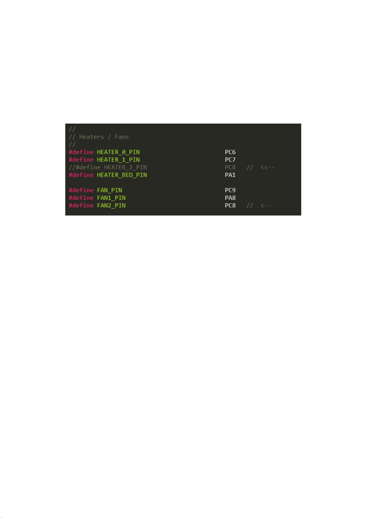
5.2 REMAPPING OUTPUTS
Note that it is usually possible to re-map the outputs as required in firmware. For instance, if you only
need two heater outputs, and want three fans, HE2 can be repurposed as a third fan output.
Steps to do this vary by firmware. When using Marlin, one solution is to edit the
pins_RUMBA32_common.h file, comment out the entry for HEATER_2, and add an extra entry for a
third fan to replace it. This is shown in Figure 3.
Figure 3: Adding a third fan in Marlin

RUMBA32 V1.1 User Manual – Rev A Page 9
6ENDSTOP CONNECTORS
RUMBA32 has six endstop inputs, designated X-MIN, X-MAX, Y-MIN, Y-MAX, Z-MIN and Z-MAX.
Most bed sensors / z-probes may also be connected through one of these connectors. It is fairly
common to use the Z-MIN connector for this (specific details will vary by sensor type and firmware
configuration).
Each endstop connector has a power pin, ground pin, and signal pin.
The power pins are supplied by the 3.3V rail by default. They can be set to supply 5V by modifying the
board jumpers (see Configuration Jumpers).
Figure 4: Endstop Connectors
Each signal pin is pulled-up to 3.3V (or 5V) by a 4.7K resistor. Additionally, each endstop signal passes
through an RC filter, consisting of a 10K resistor and a 2.2nF capacitor. As this 10K resistor limits the
current that the microcontroller will sink in the event of an overvoltage, the endstop signal pins can
be safely connected to 12/24V without damaging the board. However, it is not recommended to
operate the board in this condition.
Note: It is recommended to disable endstop pull-up resistors in your firmware. The hardware pull-up
resistors accomplish this, and the internal pull-ups enabled by firmware will form a divider with the
series resistor and may prevent correct reading under some circumstances.
Note: The endstop signals can also be controlled by attached stepper drivers if they feature a
diagnostic output pin (such as TMC drivers with StallGuard detection). If a stepper driver with this pin
is connected, it may override the connected endstop and prevent correct detection. Refer to
Diagnostic Input (StallGuard) for more information.
RUMBA32 V1.1 User Manual – Rev A Page 10
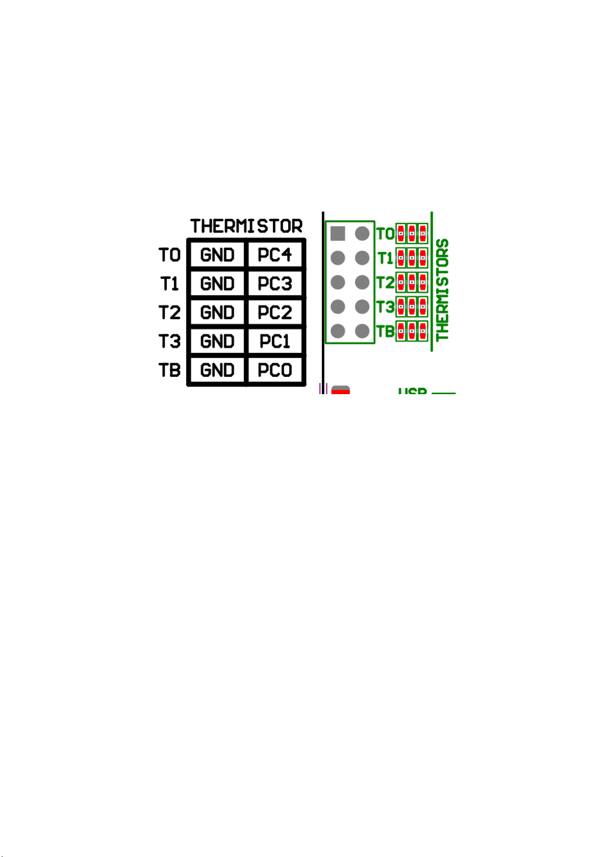
7THERMISTOR CONNECTORS
RUMBA32 has five thermistor inputs, designated T0, T1, T2, T3 and TB.
Each thermistor signal passes through an RC filter, consisting of a 10K resistor and a 1uF capacitor.
Thermistors are not polarised – it does not matter which wire connects to ground, and which to the
signal pin.
Figure 5: Thermistor Connectors

RUMBA32 V1.1 User Manual – Rev A Page 12
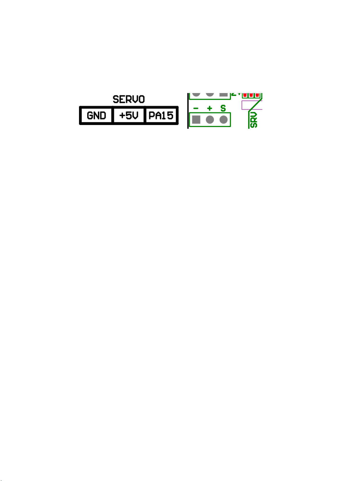
9SERVO CONNECTOR
RUMBA32 has one dedicated connector for RC servo motors. This connector provides 5V power, along
with a control signal from the microcontroller.
Figure 7: Servo Connector
RUMBA32 V1.1 User Manual – Rev A Page 13
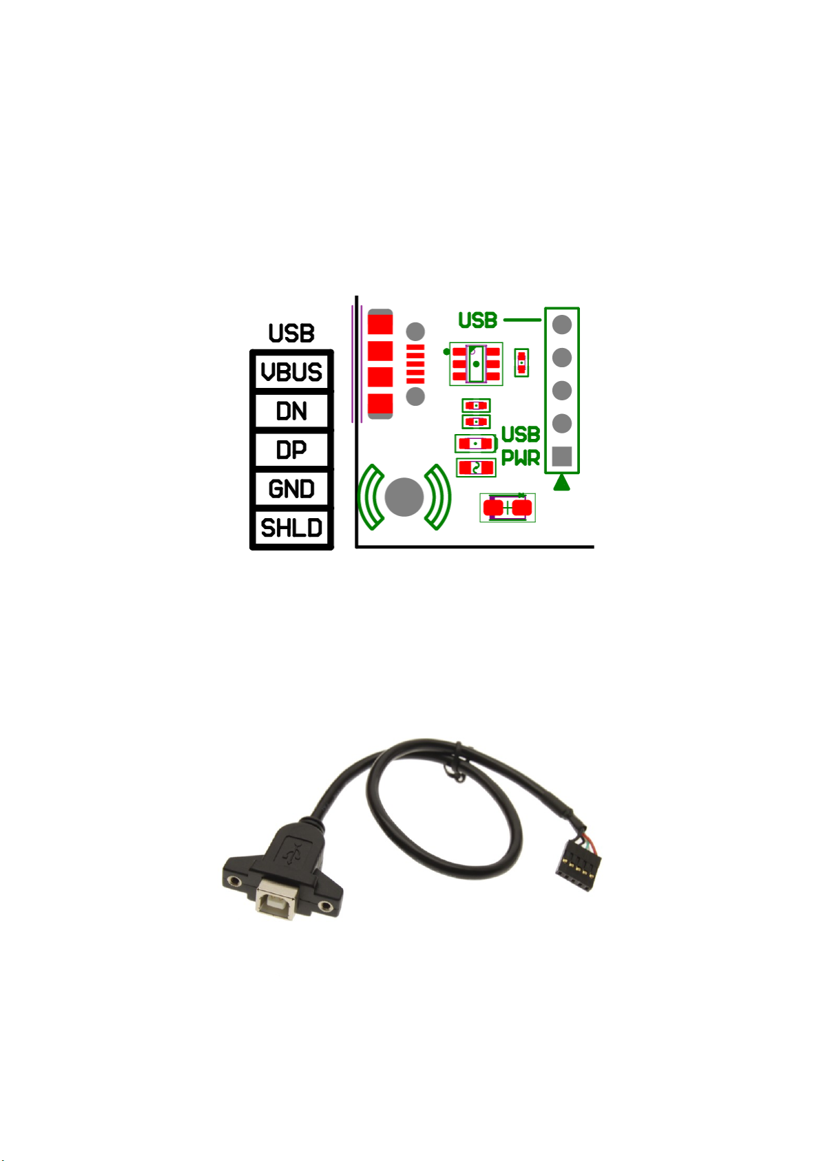
10 USB INTERFACE
USB connection to RUMBA32 is via a standard Micro-USB socket. This can be used to provide 5V power
to the board, to communicate over USB serial, and to upload firmware to the board.
There is a 200mA PTC resettable fuse in line with the power from the USB connector. This prevents
RUMBA32 from drawing excessive current and potentially damaging the host device if there is a short
circuit or other wiring problem.
Figure 8: USB Connector
The USB pin header provides additional access to the USB signals. It matches the internal USB pinout
used by ATX motherboards and can be used to connect external USB connectors – such as a panel
mount connector, as shown in Figure 9.
Figure 9: Example USB Panel-Mount Connector

RUMBA32 V1.1 User Manual – Rev A Page 14
11 EXP1 AND EXP2 –LCD CONNECTORS
EXP1 and EXP2 can be used to connect a variety of displays that use this common pinout.
Figure 10: EXP1 and EXP2 Connectors
Examples of displays that use this pinout include the RRD Graphic Smart Controller or the RRD LCD
Smart Controller (see Figure 11). Both types of displays shown have been tested with RUMBA32 and
work correctly. Most displays that use these connectors are similar and should also work, but it is
possible that some displays will not work correctly with the 3.3V logic levels.
Note that any display connected will require enabling/configuring in firmware before it can be used.
Figure 11: RRD Graphic Smart Controller (left) and RRD Character Smart Controller (right)
RUMBA32 V1.1 User Manual – Rev A Page 15
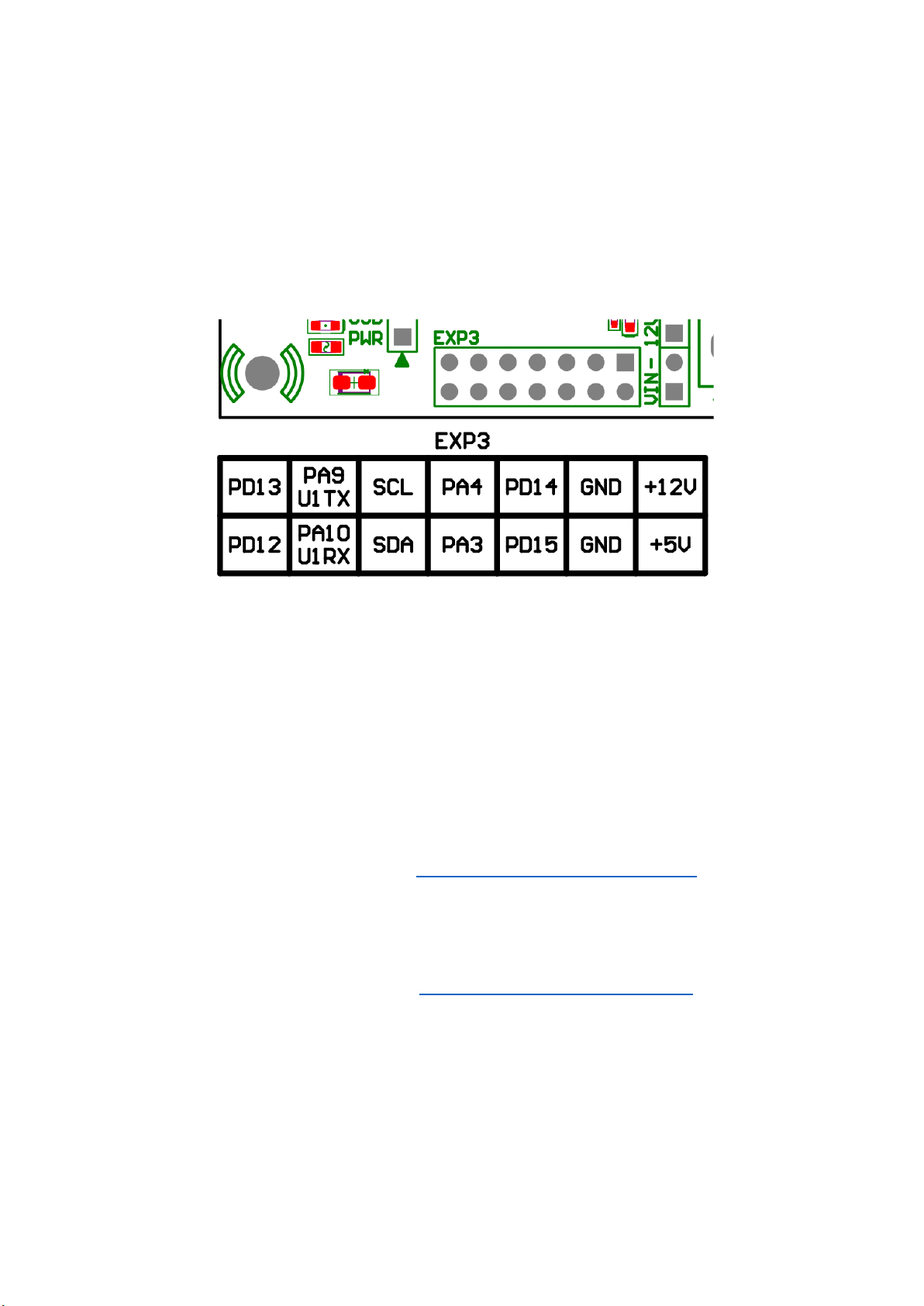
12 EXP3 –GENERAL EXPANSION HEADER
12.1 OVERVIEW
EXP3 is an expansion header consisting of two rows of seven pins. The EXP3 header is a consistent
header pinout that has been present on all RUMBA32, RUMBA+ and RUMBA boards.
EXP3 provides access to power from the 5V and 12V rails, along with several IO, including PWM
outputs, analog inputs, I2C and UART.
Figure 12: EXP3 Connector
12.2 EXP3 MODULES
EXP3 is a convenient way to attach add-on modules to the RUMBA family of boards. There are
currently two EXP3 modules developed by Aus3D.
12.2.1 RUMBA WiFi Adaptor
This module integrates an ESP8266 WiFi module into a plug-and-play module that can be connected
directly to RUMBA boards, without the need for any additional wiring. It can be used to access and
control the printer using a web interface over WiFi. The printer firmware needs to be configured to
support this (typically be enabling serial on USART1).
For more information on this adaptor, visit: https://github.com/Aus3D/RUMBA-WIFI
12.2.2 RUMBA MKS-TFT Adaptor
This is an adaptor that makes it possible to connect a range of TFT displays from Makerbase. The
printer firmware needs to be configured to support this (typically be enabling serial on USART1).
For more information on this adaptor, visit: https://github.com/Aus3D/RUMBA-TFT
RUMBA32 V1.1 User Manual – Rev A Page 16
13 STEPPER DRIVERS
13.1 OVERVIEW
RUMBA32 has sockets for up to six stepper drivers, designated X, Y, Z, E0, E1 and E2.
Note that the purpose of these stepper drivers can typically be remapped in firmware – for instance,
Marlin firmware will allow the use of E0/E1/E2 as a second Z axis stepper driver.
Each stepper driver socket can be individually set to control a stepper driver in the following modes:
•Traditional – configure the stepper driver by setting the MS1, MS2 and MS3 jumpers.
•SPI – configure the stepper driver using the SPI interface.
•UART – configure the stepper driver using the UART interface.
Note that not all stepper drivers from all manufacturers and suppliers use the same pinout for SPI and
UART modes. Some stepper drivers may offer multiple pinouts as selected by solder jumpers and may
be set differently by default by different suppliers.
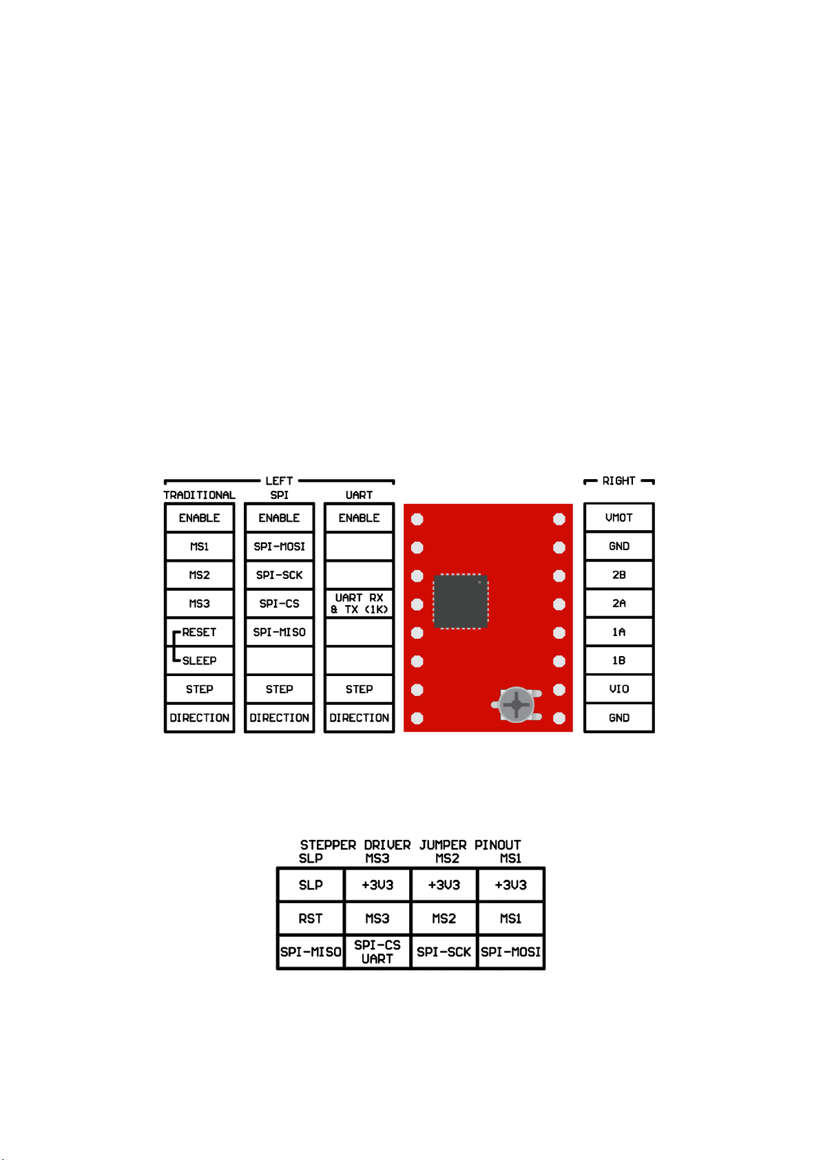
RUMBA32 has been designed to work with the following stepper driver pinouts:
Figure 13: Stepper Driver Socket Pinout
The jumpers underneath each stepper driver are used to configure the mode. They have the following
pinout:
Figure 14: Stepper Driver Jumper Pinout
Example jumper configurations for common stepper drivers are given in Stepper Driver Jumper
Examples.
RUMBA32 V1.1 User Manual – Rev A Page 17
13.2 DIAGNOSTIC INPUT (STALLGUARD)
RUMBA32 provides an easy way to connect stepper drivers to the endstop pins. This can be useful
when using TMC stepper drivers with StallGuard detection, in order to implement sensorless homing.
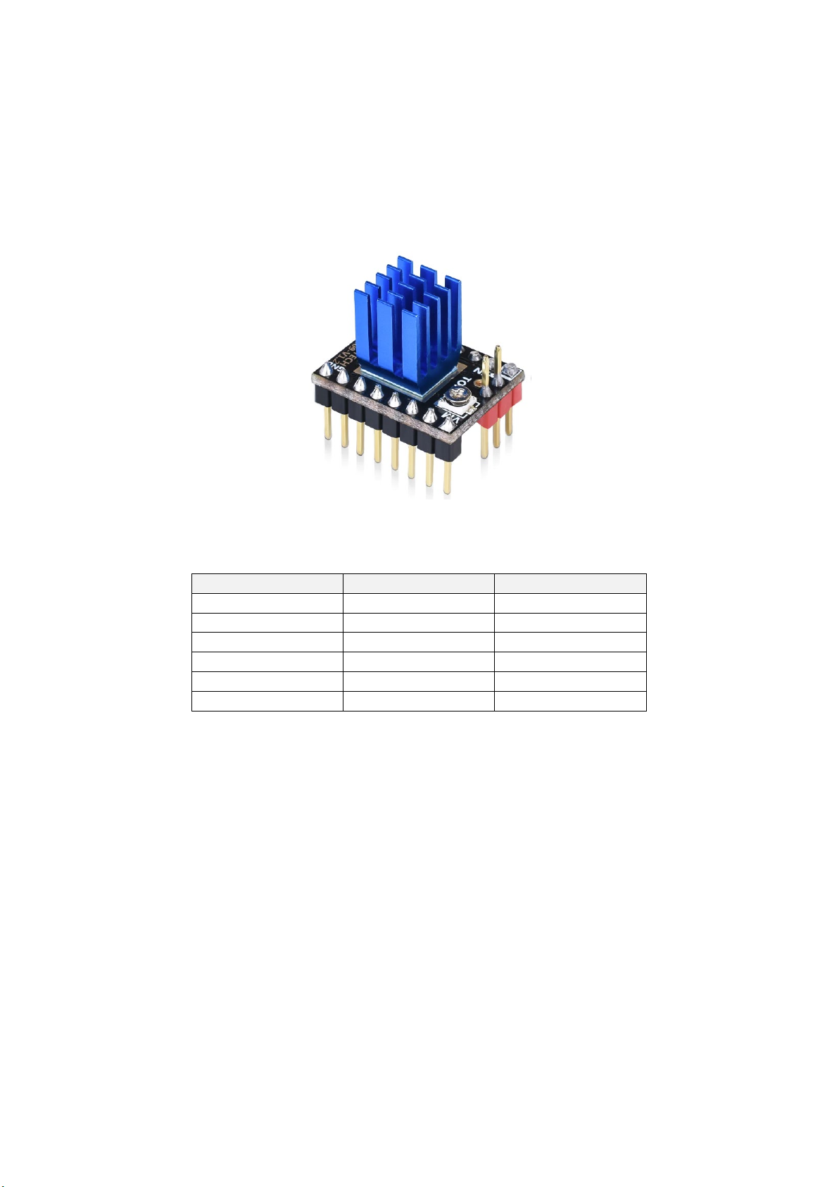
Each stepper driver socket features a pin that can connect the stepper driver to an associated endstop
input. This requires the stepper driver to have the DIAG pin installed. An example of such a driver is
shown in Figure 15.
Figure 15: TMC2209 with DIAG pin (red pin, third from edge) installed
The drivers and endstops are matched as follows:
Stepper Driver
Endstop Signal
Microcontroller Pin
X
X-MIN
PB12
Y
Y-MIN
PB15
Z
Z-MIN
PD9
E0
X-MAX
PB13
E1
Y-MAX
PD8
E2
Z-MAX
PD10
For TMC stepper drivers that have this DIAG pin, sensorless homing can be enabled in firmware
without requiring any additional wiring.
13.2.1 Conflict with Endstop Signal
When connecting stepper drivers with the DIAG pin installed, the stepper driver’s DIAG signal may
override any connected endstop and prevent it from being detected by the firmware.
If you are using a stepper driver with the DIAG pin, but do not require StallGuard and intend to use
the associated endstop, it is recommended to ensure that the DIAG signal is not connected. This can
be achieved the following ways:
•Remove (desolder or trim away) the DIAG pin from the stepper driver
•Remove (desolder or trim away) the DIAG connector in the driver socket on RUMBA32
•Bend the DIAG connector on RUMBA32 so that the driver DIAG pin does not enter it
•Desolder the resistor on RUMBA32 immediately below the DIAG connector

RUMBA32 V1.1 User Manual – Rev A Page 18
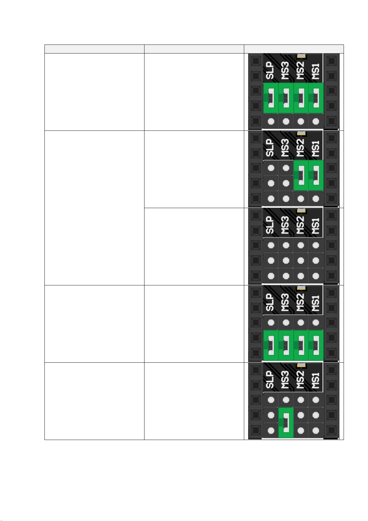
13.3 STEPPER DRIVER JUMPER EXAMPLES
Stepper Driver
Desired Mode
Jumper Positions
A4988
Microstepping = 1x
Microstepping = 2x
Microstepping = 4x
Microstepping = 8x
Microstepping = 16x

RUMBA32 V1.1 User Manual – Rev A Page 19
Stepper Driver
Desired Mode
Jumper Positions
DRV8825
Microstepping = 1x
Microstepping = 2x
Microstepping = 4x
Microstepping = 8x
Microstepping = 16x
RUMBA32 V1.1 User Manual – Rev A Page 20
Stepper Driver
Desired Mode
Jumper Positions
Microstepping = 32x
TMC2100
Mode = SpreadCycle
Microstepping = 16x
Mode = StealthChop
Microstepping = 16x
Interpolation = 256x
TMC2130
TMC2160
TMC5160
TMC5161
SPI Communication
TMC2208
TMC2209 UART Communication
Table of contents


