E-2
Note:
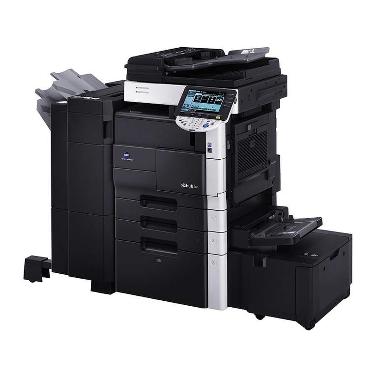
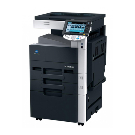
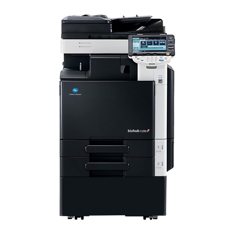
• This manual provides the illustrations of the
accessory parts and machine that may be
slightly different in shape from yours. In that
case, instead of the illustrations, use the
appearance of your machine to follow the
installation procedure. This does not cause any
significant change or problem with the proce-
dure.
<C554e/C454e/C364e/C284e/C224e/C554/C454/
C364/C284/C224/554e/454e/364e/284e/224e>
• The contents of this manual are for the unit with
the Authentication Unit installed AU-201S/AU-
201.
• To use this product, the Authentication Unit
AU-201S/AU-201 is required.
• For information on the procedure for attaching
the Authentication Unit AU-201S/AU-201 to the
Working table, see the installation manual of
Authentication Unit AU-201S/AU-201.
<C368/C308/C258>
• The contents of this manual are for the unit with
the Authentication Unit installed AU-201S.
• To use this product, the Authentication Unit
AU-201S is required.
• For information on the procedure for attaching
the Authentication Unit AU-201S to the Working
table, see the installation manual of Authentica-
tion Unit AU-201S.
<C287/C227/367/287/227>
• The contents of this manual are for the unit with
the Authentication Unit installed AU-201S.
• To use this product, the Authentication unit AU-
201S and the Local Interface Kit EK-609/EK-
608 are required.
• For information on the procedure for attaching
the Authentication unit AU-201S to the Working
table, see the installation manual of Authentica-
tion unit AU-201S.
• When mounting the Upgrade Kit UK-212 at the
same time, mount the Upgrade Kit UK-212 first.
2. Installation procedures
<Installations to models C554e/C454e/C364e/
C284e/C224e/C554/C454/C364/C284/C224/554e/
454e/364e/284e/224e>
(1) Turn OFF the power switch and unplug the
power cord from the power outlet.
(2) Attach the ferrite core supplied with the Authenti-
cation Unit AU-201S/AU-201 to the Authentica-
tion Unit AU-201S/AU-201 at the position shown
in the illustration.
Note:
• Place the ferrite core such that the cable is
wound twice around the ferrite core.
• Place the ferrite core approximately 60 mm
away from the authentication unit.
<Installations to models C554e/C454e/C364e/
C284e/C224e/C554/C454/C364/C284/C224/554e/
454e/364e/284e/224e>
Follow the installation procedures starting on page
E-2.
<Installations to models C368/C308/C258>
Follow the installation procedures starting on page
E-6.
<Installations to models C287/C227/367/287/227>
Follow the installation procedures starting on page
E-10.
