AussieCarHoists YL5000 User manual

1 / 32
jj YL5000
Wheel Alignment Four Post Lift
Capacity 5000Kg
USER’S MANUAL

2 / 32
Index
Chapter 1 General Information..................................................................................................4
1.1
Manual Keeping ...........................................................................................................4
1.2
Obligation in case of malfunction.................................................................................4
1.3
Cautions for the safety of the operator..........................................................................5
1.4
Warnings ......................................................................................................................5
Chapter 2 Product Identification..............................................................................................6
2.1
Warranty.......................................................................................................................6
2.2
Technical Service.........................................................................................................6
Chapter 3 Packing, Transport and Storage...........................................................................7
3.1 Packing..........................................................................................................................7
3.2 Lifting and Handling.....................................................................................................7
3.3 Storage and Stacking of the Package ............................................................................7
3.4 Delivery and check of packages....................................................................................7
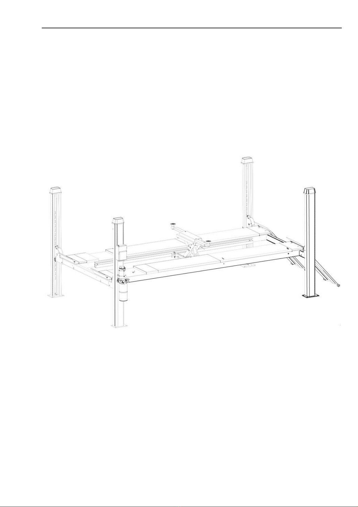
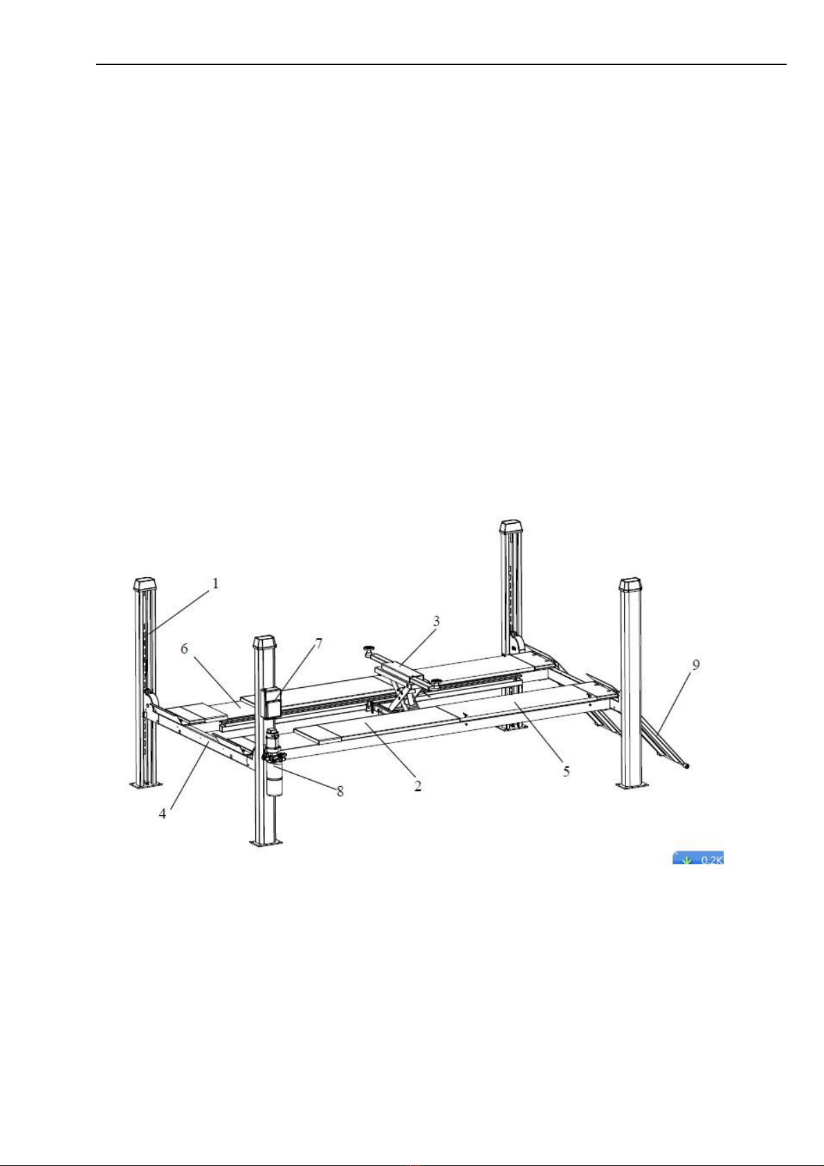
Chapter 4 Product Description.................................................................................................8
Chapter 5 Technical Specification...........................................................................................9
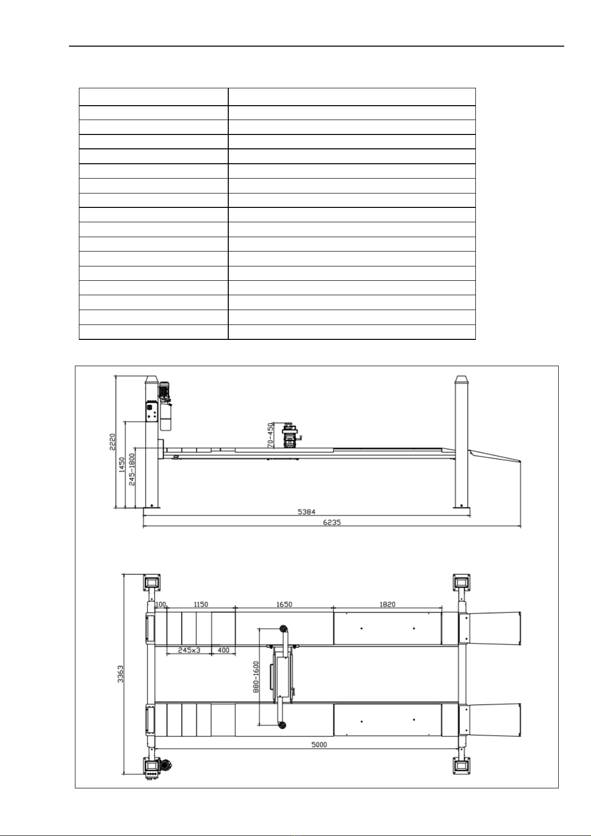
5.1 Technical Data................................................................................................................9
5.2 Lift Dimension Rough Drawing.....................................................................................9
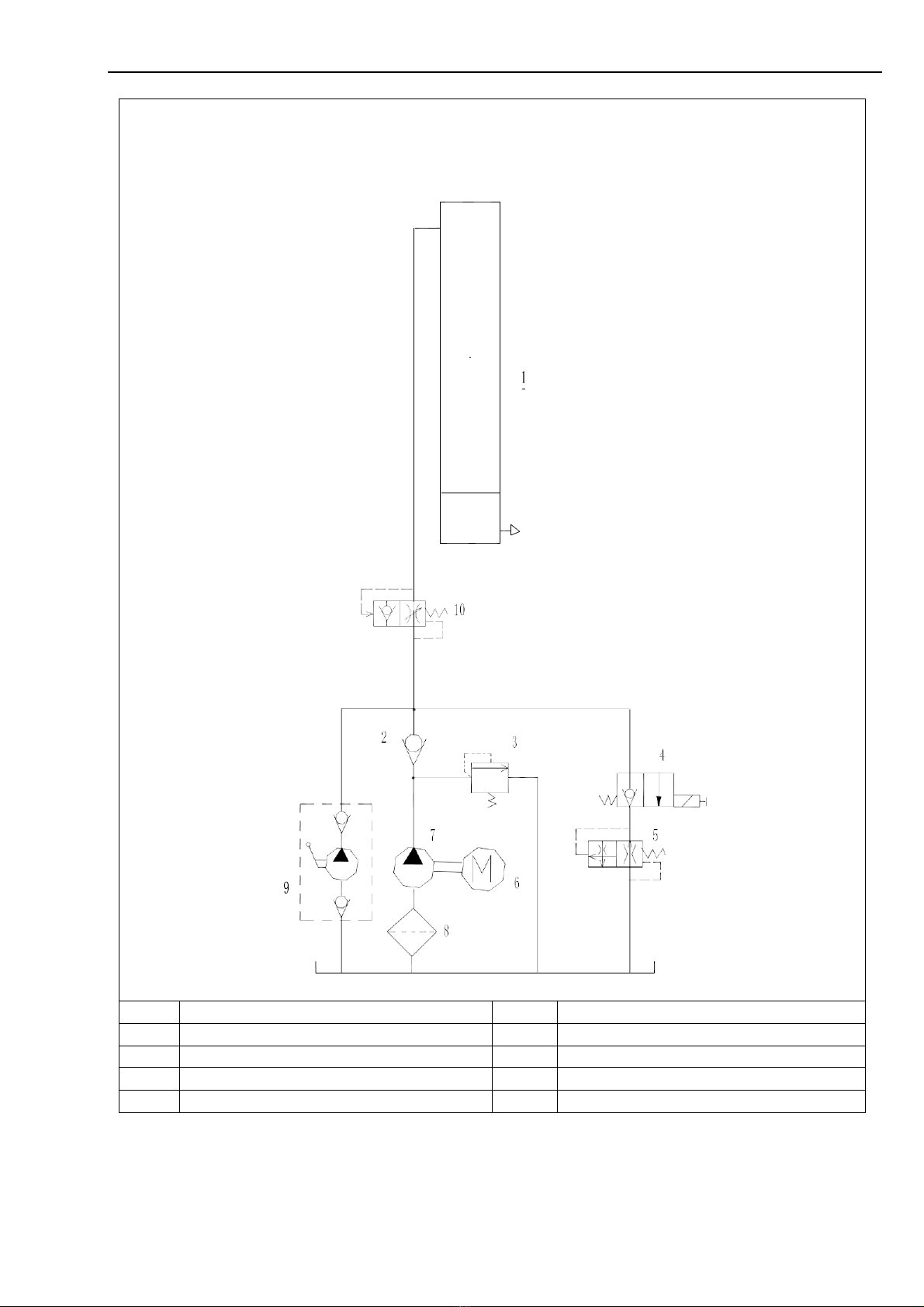
5.3 Hydraulic Drawing.......................................................................................................11
5.4 Electrical Drawing (380V/400V-3Ph) .........................................................................12
5.5 Wiring Diagram............................................................................................................13
5.6 Pneumatic Drawing......................................................................................................15
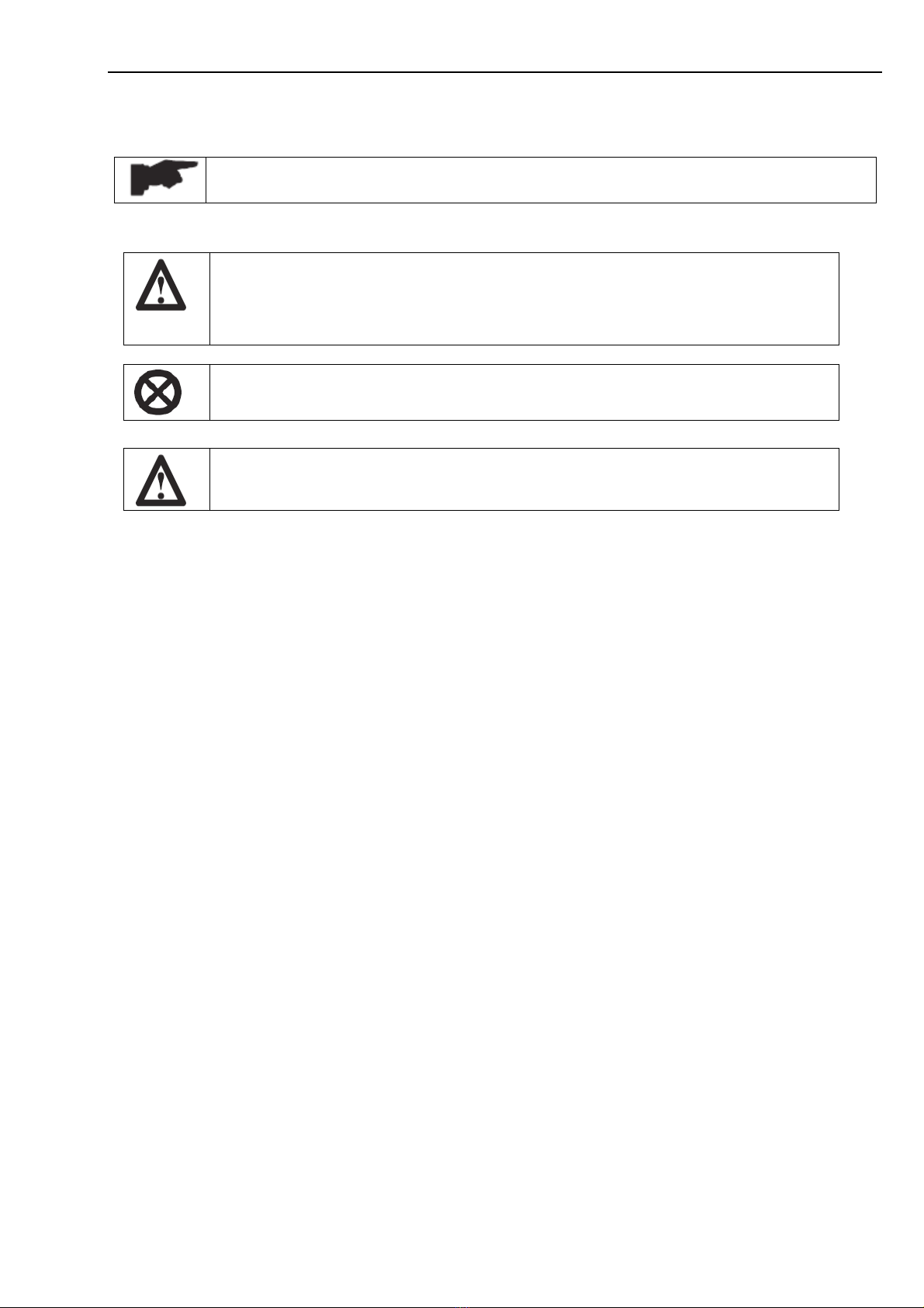
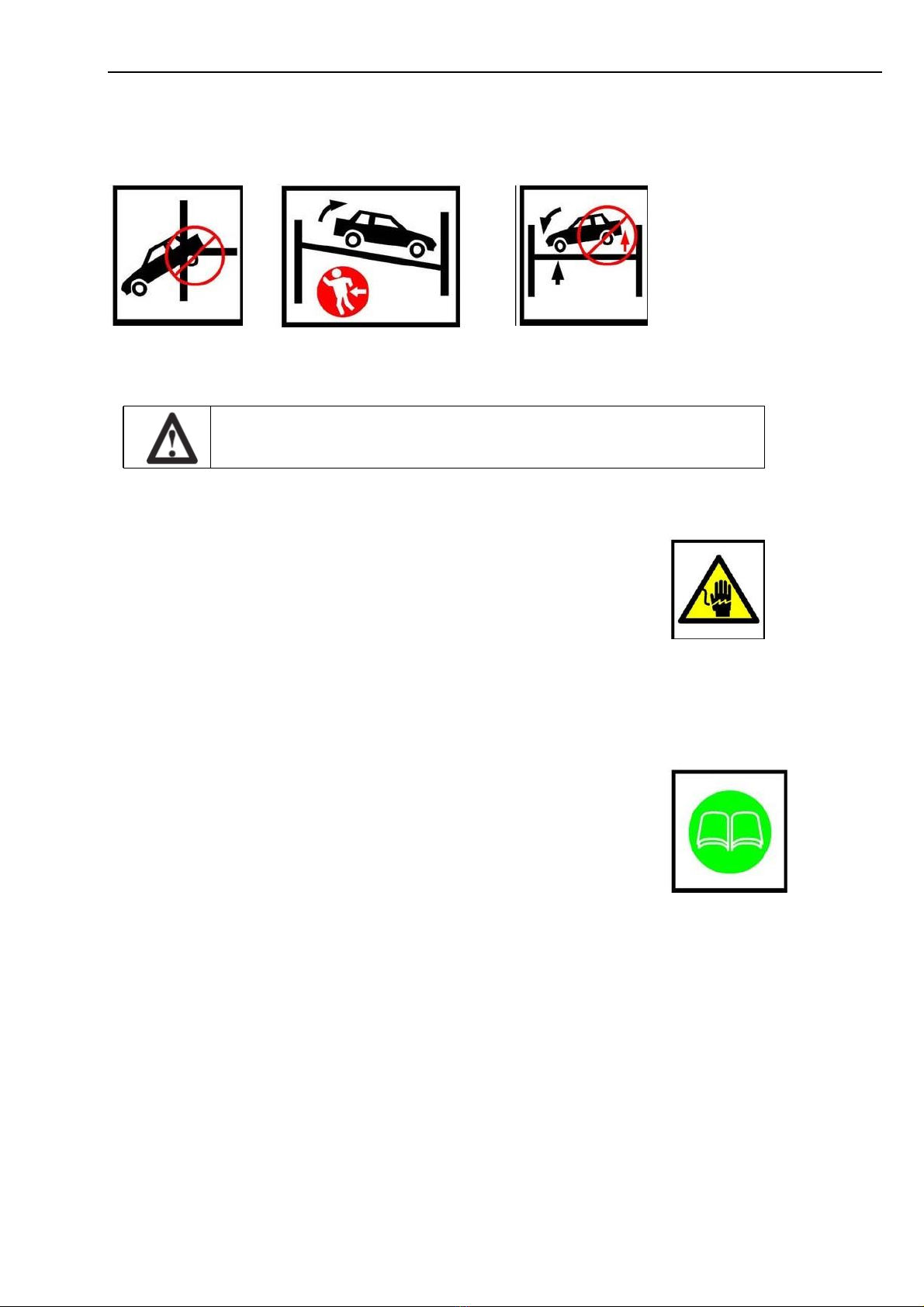
Chapter 6 Safety.........................................................................................................................16
6.1 General Warnings.......................................................................................................16
6.2 Risk for the people .....................................................................................................16
6.3 Personnel Crushing Risks...........................................................................................16
6.4 Risk of the Vehicle falling from the lift.....................................................................17
6.5 Slipping Risk..............................................................................................................17
6.6 Electrocution Risk......................................................................................................17
6.7 Risk Resulting from improper lighting ......................................................................17
6.8 Risk of breaking component during operation...........................................................17
6.9 Risk for unauthorized uses.........................................................................................18
6.10 Risk during vehicle lifting and working.....................................................................18
Chapter 7 Installation................................................................................................................19
7.1 Tools for installation ..................................................................................................19
7.2 Checking for room suitability ....................................................................................19
7.3 Lighting......................................................................................................................19
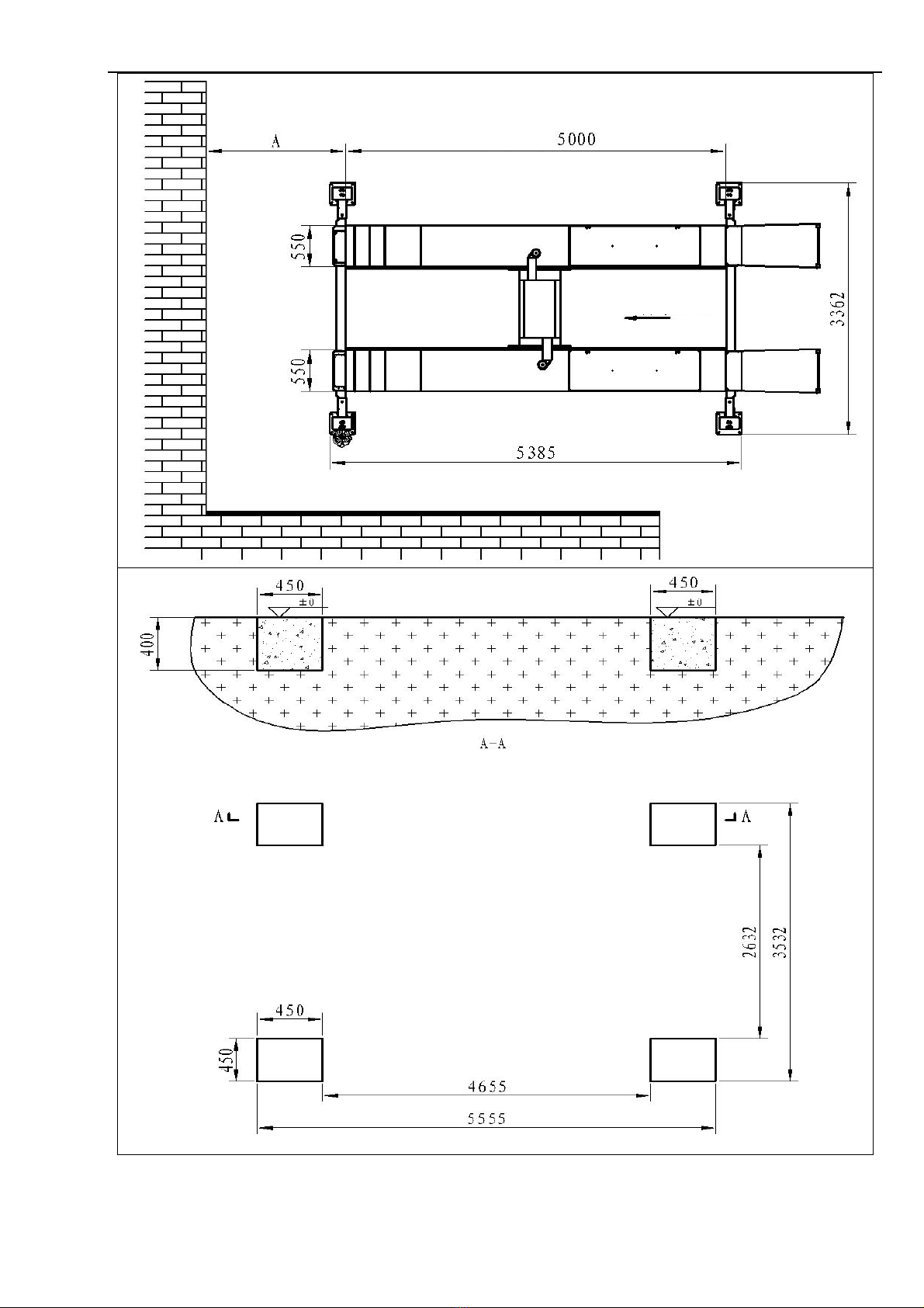
7.4 Installation surface .....................................................................................................19
7.5 Site Layout .................................................................................................................19
7.6 Installation of runways and transverse beans.............................................................20
7.7 Steel Cable Routing Plan (Very Important)...............................................................21
7.8 Installation of safety Lock..........................................................................................23
7.9 Installation of the columns.........................................................................................24
7.10 Anchoring the columns ..............................................................................................24
7.11 Hydraulic system connection......................................................................................25
7.12 Installation of Jack......................................................................................................25
7.13 Pneumatic system connection ....................................................................................26
7.14 Make the electrical hookup to the power unit............................................................26
7.15 Start up .......................................................................................................................26
7.16 Check and adjustment ................................................................................................27
7.17 Limit switch installation.............................................................................................27
7.18 Accessories Installation..............................................................................................28
7.19 Check with load..........................................................................................................28
Chapter 8 Operation and Use..................................................................................................29

3 / 32
8.1 Controls......................................................................................................................29
8.2 To raise the lift ...........................................................................................................30
8.3 To lower the lift..........................................................................................................30
8.4 Jack Operation............................................................................................................30
Chapter 9 Maintenance.............................................................................................................30
9.1 Ordinary Maintenance................................................................................................30
9.2 Periodic Maintenance.................................................................................................30
Chapter 10 Troubleshooting....................................................................................................31

4 / 32
Chapter 1 General Information
This chapter contains warning instructions to operate the lift properly and prevent injury to operators
or objects.
This manual has been written to be used by shop technicians in charge of the lift (operator)
and routine maintenance technician (maintenance operator).
The operating instructions are considered to be an integral part of the machine and must remain with
it for its whole useful life.
Read every section of this manual carefully before operating the lift and unpacking it since it
gives helpful information about:
-SAFETY OF PEOPLE
-SAFETY OF THE LIFT
-SAFETY OF LIFTED VEHICLES
The company is not liable for possible problems, damage, accidents, etc. resulting from failure to
follow the instructions contained in this manual.
Only skilled technicians of Authorized dealers or service centers authorized by the manufacturer
shall be allowed to carry out lifting, transport, assembling, installation, adjustment, calibration,
settings, extraordinary maintenance, repairs, overhauling and dismantling of the lift.
THE MANUFACTURER IS NOT RESPONSIBLE FOR POSSIBLE DAMAGE TO PEOPLE, VEHICLES OR
OBJECTS
IF SAID OPERATIONS ARE CARRIED OUT BY UNAUTHORIZED PERSONNEL OR THE LIFT IS
IMPROPERLY
USED.
Any use of the machine made by operators who are not familiar with the instructions and
procedures contained herein shall be forbidden.
1.1
Manual Keeping
For a proper use of this manual, the following is recommended:
•
Keep the manual near the lift, in an easily accessible place.
•
Keep the manual in an area protected from the damp.
•
Use this manual properly without damaging it.
•
Any use of the machine made by operators who are not familiar with the instructions
and procedures contained herein shall be forbidden.
This manual is an integral part of the lift: it shall be given to the new owner if and when the lift
is resold.
1.2
Obligation in case of malfunction
In case of machine malfunction, follow the instructions contained in the following
chapters.

5 / 32
1.3
Cautions for the safety of the operator
Operators must not be under the influence of sedatives, drugs or alcohol when operating the
machine.
Before operating the lift, operators must be familiar with the position and function of all
controls, as well as the machine features shown in the chapter “Operation and use”
1.4
Warnings
Unauthorized changes and/or modifications to the machine relieve the
manufacturer of any liability for possible damages to objects or people. Do not
remove or make inoperative the safety devices, this would cause a violation of
safety at work laws and regulations.
Any other use which differs from that provided for by the manufacturer of the
machine is strictly forbidden.
The use of non genuine parts may cause damage to people or objects
DECLARATION OF WARRANTY AND LIMITATION OF LIABILITY
The manufacturer has paid proper attention to the preparation of this manual. However, nothing
contained herein modifies or alters, in any way, the terms and conditions of manufacturer
agreement by which this lift was acquired, nor increase, in any way, manufacturer’s liability to the
customer.
TO THE READER
Every effort has been made to ensure that the information contained in this manual is correct,
complete and up-to date. The manufacturer is not liable for any mistakes made when drawing up
this manual and reserves the right to make any changes due the development of the product, at any
time.

6 / 32
Chapter 2 Product Identification
The identification data of the machine are shown in the label placed on the machine.
Below is a blank sample for reference. For the real place please check on the machine.
Four Post Lift CE
Model No.
Power Supply
Lift Capacity(Kg)
Min Height (mm)
Jack Capacity(Kg)
Max Height (mm)
Serial No.
Manufacture Date
Made in China for XXXX
Use the above data both to order spare parts and when getting in touch with the
manufacturer (inquiry). The removal of this label is strictly forbidden.
Machines may be updated or slightly modified from an aesthetic point of view and, as a
consequence, they may present different features from these shown, this without prejudicing what
has been described herein.
2.1
Warranty
The warranty is valid for a period of 12 months starting from the date of the purchase invoice.
The warranty will come immediately to an end when unauthorized modifications to the machine
or parts of it are carried out.
The presence of defects in workmanship must be verified by the Manufacturer’s personnel in charge.
2.2
Technical Service
For all servicing and maintenance operations not specified or shown in these instructions,
contact your dealer where the machine has been bought or the Manufacturer’s Sales Department.
Only skilled personnel who are familiar with the lift and this manual shall be allowed to carry
out packing, lifting, handling, transport and unpacking operations.

7 / 32
Chapter 3 Packing, Transport and Storage
3.1 Packing
The packing of the lift is delivered in following components:
⚫columns wrapped up in non-scratch material sealed with 2 straps, each 2 columns packed in one
package
⚫runways each wrapped up in non-scratch material
⚫transverse beams each wrapped in non-scratch material
⚫jack wrapped up in non-scratch material
⚫power unit and the control panel and other accessories packed in a plywood box
⚫ramps wrapped in non-scratch material
(If customer has special request the packing will also be changed accordingly).
3.2 Lifting and Handling
When loading/unloading or transporting the equipment to the site, be sure to use suitable loading
(e.g. cranes, trucks) and hoisting means. Be sure also to hoist and transport the components
securely so that they cannot drop, taking into consideration the package’s size, weight and centre
of gravity and it’s fragile parts.
Hoist and handle only one package at a time
3.3 Storage and Stacking of the Package
Packages must be stored in a covered place, out of direct sunlight and in low humidity, at a
temperature between 10°C and +40°C. Stacking is not recommended: the package’s narrow base,
as well as its considerable weight and size make it difficult and hazardous.
3.4 Delivery and check of packages
When the lift is delivered, check for possible damages due to transport and storage; verify that what
is specified in the manufacturer’s confirmation of order is included. In case of damage in transit, the
customer must immediately inform the carrier of the problem.
Packages must be opened paying attention not to cause damage to people
(Keep a safe distance when opening straps) and parts of the lift (be careful the objects do not
drop from the package when opening).

8 / 32
Chapter 4 Product Description
Four Post Lift Rough Description
This four post lift has been designed for the lifting of motor-vehicles for wheel alignment
and normal maintenance.
The maximum lifting weight is as specified on the serial plate.
Most of mechanical parts such as runway, transverse beams have been built in steel plate to make
the lift stiff and strong while keeping a low weight.
The electro-hydraulic operation is described in details in chapter 8.
This chapter describes the lift’s principal elements, allowing the user to be familiar with the machine.
As shown in below picture, the lift is composed of below parts:
1) Column, 4pcs
2) Platform, 2pcs
3) Pneumatic-hydraulic jack, 1pcs, Optional 2pcs
4) Transverse beam, 2pcs
5) Rear slipping plates, 2pcs
6) Groove for the turntable, 2pcs
7) Control panel, 1pcs
8) Hydraulic power unit, 1pcs
9) Drive-on ramp, 2pcc

9 / 32
Chapter 5 Technical Specification
5.1 Technical Data
Lift Capacity
5000kg
Jack Capacity
2500kg
Maximum Lifting Height
1800mm
Minimum Height
215mm
Jack raised height
450mm
Runway length
5100mm
Runway width
508mm
Free width between runways
850-1050mm
Width between two columns
2750mm
Overall length
5460mm
Overall height
2200mm
Overall width
3362mm
Raised time
60s
Noise level
80 dB(A)/1m
Rated pneumatic pressure
6bar –8bar
Working temperature
-10 °C - 40 °C
Average weight of package
1800kg
5.2 Lift Dimension Rough Drawing

10 / 32

11 / 32
5.3 Hydraulic Drawing
1
Main hydraulic cylinder
6
Motor
2
Non return valve
7
Gear pump
3
Maximum pressure valve
8
Oil filter
4
Lowering solenoid valve
9
Emergency hand pump - optional
5
Lowering control valve
10
Parachute valve - optional

12 / 32
5.4 Electrical Drawing (380V/400V-3Ph)

13 / 32
5.5 Wiring Diagram

14 / 32

15 / 32
5.6 Pneumatic Drawing
Pneumatic cylinders
Solenoid air valve
Water separator and lubricator
Compressed air supply

16 / 32
Chapter 6 Safety
Read this chapter carefully and completely because it contains important information for the safety
of the operator and the person in charge of maintenance.
The lift has been designed and built for lifting vehicles and making them stand
above level in a closed area. Any other use is forbidden.
The manufacturer is not liable for possible damages to people, vehicles or objects
resulting from an improper or unauthorized use of the lift.
For operator and people safety, a safety area at least 1m free away from the lift must be
vacated during lifting and lowering. The lift must be operated only from the operator’s control
site in this safety area.
Operator’s presence under the vehicle, during working, is only admitted when the vehicle is lifted
and runways are not running.
Never use the lift when safety devices are off-line. People, the lift and the
vehicles lifted can be seriously damaged if these instructions are not followed.
6.1 General Warnings
The operator and the person in charge of maintenance must follow accident-prevention laws and
rules in force in the country where the lift is installed
They also must carry out the following:
•
neither remove nor disconnect hydraulic, electric or other safety devices;
•
carefully follow the safety indications applied on the machine and included in the manual;
•
observe the safety area during lifting;
•
be sure the motor of the vehicle is off, the gear engaged and the parking brake put on;
•
be sure only authorized vehicles are lifted without exceeding the maximum lifting capacity;
•
Verify that no one is on the runways during lifting or standing.
Any use of the lift other than that herein specified can cause serious accidents to
people in close proximity of the machine.
6.2 Risk for the people
All risks the personnel could run, due to an improper use of the lift, are described in this section.
6.3 Personnel Crushing Risks
During lowering of runways and vehicles, personnel must not be within the area covered by the
lowering trajectory. The operator must be sure no one is in danger before operating the lift.

17 / 32
6.4 Risk of the Vehicle falling from the lift
Vehicle falling from the lift can be caused when the vehicle is improperly placed on platforms, and
when its dimensions are incompatible with the lift or by excessive movement of the vehicle.
In this case, keep immediately away from the working area.
6.5 Slipping Risk
The risk of slipping can be caused by oil or dirt on the floor near the lift.
Keep the area under and around the lift clean. Remove all oil spills.
6.6 Electrocution Risk
Avoid use of water, steam, and solvent, varnish jets in the lift area
where electric cables are placed and, in particular, next to the electric
panel.
6.7 Risk Resulting from improper lighting
Make sure all areas next to the lift are well and uniformly lit, according to local
regulations.
6.8 Risk of breaking component during operation
Materials and procedures, suitable for the designed parameters of the
lift, have been used by the manufacturer to build a safe and reliable
product. Operate the lift only for the use it has been designed for
and follow the maintenance schedule shown in the chapter
“Maintenance”.

18 / 32
6.9 Risk for unauthorized uses
The presence of unauthorized persons next to the lift and on the
platforms is strictly forbidden during lifting as well as when the vehicle
has been already lifted
6.10 Risk during vehicle lifting and working
To avoid overloading and possible breaking during lifting and working, the following safety
devices have been used:
•
A maximum pressure valve placed inside the hydraulic unit to prevent excessive weight.
The maximum pressure valve has been preset by the manufacturer to a
proper pressure. Do not try to adjust it to overrun the rated lifting capacity.
•
A special design of the safety mechanism
built in each column to prevent the lift
from sudden lowering in case of the cable
failure.
It is strictly forbidden to modify any safety device. Always ensure the safety
device for proper operation during the service.

19 / 32
Chapter 7 Installation
Only skilled technicians, appointed by the manufacturer, or by authorized
dealers, must be allowed to carry out installation. Serious damage to people
and to the lift can be caused if installations are made by unskilled personnel.
Always refer to the exploded views attached during installation.
7.1 Tools for installation
✟Rotary Hammer Drill ¢16 ✟Hex-Key/Allen Wrench Set
✟Masonry Bit ✟Crow Bar for Shim Installation
✟Hammer ✟Chalk Line
✟Level ✟Medium Cross Screwdriver
✟Open-End Wrench Set ✟Medium Flat Screwdriver
✟Medium Crescent Wrench ✟Tape Measure
7.2 Checking for room suitability
The lift has been designed to be used in covered and sheltered places.
The place of installation must not be next to washing areas, painting workbenches, solvent or
varnish deposits. The installation near to rooms, where a dangerous situation of explosion can
occur, is strictly forbidden. The relevant standards of the local Health and Safety at Work
regulations, for instance, with respect to minimum distance to wall or other equipment, must be
observed.
7.3 Lighting
Lighting must be carried out according to the effective regulations of the place of installation.
All areas next to the lift must be well and uniformly lit.
7.4 Installation surface
The lift must be placed concrete surface sufficiently resistant. The surface must be suitable
for bearing maximum stress values, also in unfavorable working conditions. New concrete
must be adequately cured by at least 10 days minimum. For installations on raised surface,
compliance with the maximum carrying capacity of the surface is recommended.
A level floor is suggested for proper installation. Small differences in floor
slope may be compensated for by proper shimming. Any major slope change will
affect the level lifting performance. If a floor is of questionable slope please
consider to pour the new concrete slab.
7.5 Site Layout
•
Determine which end of the lift will be approach side.
•
Determine which side the power-side runway (with the hydraulic cylinder attached) will
be located on. Remember that the power-side runway must be installed on the same side
as the power-side column.
•
For 4-post lift please do not make foundation hole for fixing bolt before you set up the lift and
adjust it well. Normally people firstly get lift, set it up, adjust then fix the post. If you prepare
the bolt hole in the foundation before lift arrival it is not a good idea.
Below drawing is for reference only.

20 / 32
Table of contents
Other AussieCarHoists Lifting System manuals
Popular Lifting System manuals by other brands

JLG
JLG DVL Series Operation and safety manual

Terex
Terex Genie Superlift Advantage SL-5 Parts and service manual

Böcker
Böcker LMX 500 Operating and maintenance instructions

Snorkel
Snorkel MHP13AT Operation manual

LGMG
LGMG SR0818D Maintenance manual

Nussbaum
Nussbaum HL 2.30 NT Operating Instruction and Documentation