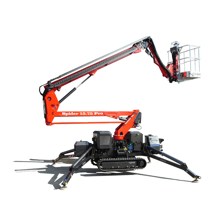
002
003
Dear Clients,
Platform Basket thanks you for your choice
Your new access equipment is the result of an innovative approach and the pursuit of quality. It has been designed
to be functional, safe, comfortable and durable with style and excellent operating features.
When your machine requires maintenance, only the spare parts supplied by us must be used in order to ensure
reliability and suitability.
INTRODUCTION
The purpose of this manual is to provide the users with the essential knowledge for carrying out the procedures nec-
essary for the proper working of the machine and for the purposes for which it is intended. All the information contained
in this manual must be READ and ASSIMILATED before undertaking any attempt to operate the machine.
THE OWNER’S MANUAL is the most important instrument. Keep it in the machine. Remember that NO EQUIP-
MENT IS SAFE if the operator does not observe the safety precautions.
Since the manufacturer has no direct control over the operation and applications of the machine, the appropriate
safety procedures are entrusted to the responsibility of the user and the user’s personnel.
All the instructions contained in this manual are based on the use of the machine when it is working CORRECTLY,
without alterations and/or modifications to the original model. Any alteration and/or modification to the machine is SE-
VERELY PROHIBITED, without the prior authorization of Platform Basket.
This “SAFETY SYMBOL” is used to call attention to potential dangers which may cause injury or death if they
are underestimated.
The safety of personnel and the appropriate operation of the machine must be the main concern. DANGER,
BEWARE, CAUTION, IMPORTANT, etc. signs are included in everywhere in this manual in order to highlight
the danger areas. They are defined as follows:
DANGER
Indicates a situation of imminent danger which will cause serious injury or death if not avoided.
BEWARE
Indicates a potentially dangerous situation which may cause minor or moderate injuries if not avoid-
ed.
This sign may also be used as a warning against dangerous practices.
WARNING
WARNING or INSTRUCTIONS indicates a procedure indispensable for safe operating conditions and if
not followed may cause a malfunction or damage to the machine.
PURPOSE OF THE MANUAL


