[F
[P
[F
[P
[F
[F
[P
i
:
a
Ihermcd lndicotion
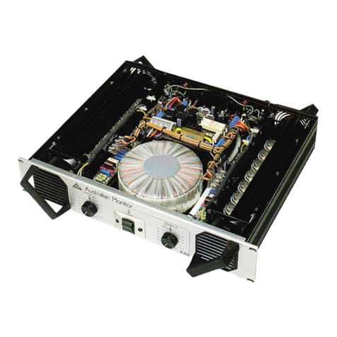
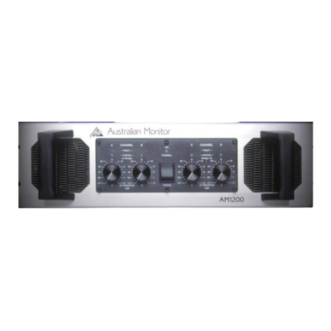
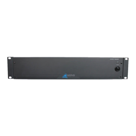
The only indicator not duplicated is the THERMAL LED. This LED is found in
the centre of the amplifier (aboue the POWER switch). When switching the
amplifier on, the light will flash red indicating correct operation of the Mains In-
Rush Suppression circuit. This light will not illuminate in normal use.
This LED will glow Red when the amplifier has shutdown due to excessive heat
build up - in this situation all indicators will extinguish and only the fans remain
operational on the unit. The unit will then automatically restart when the
internal temperatures return to a safe operating level.
PowerOn lndicolion
(Refer to Dingram aboue)
The LEDs closest to the mains switch glow Green when on. The first indicates the
amplifier is oN. (It actually indicates the 15 volt preamp supply is present - the
left hand side display shows -15v, and the right hand side shows the +lbv).
The next LED outwards is also a supply indicator and also shows power on. (It
indicates that the Positive High Tension Power Supply to the output stage is
present - on the corresponding channel).
level lndicotion
Each channel features a variable 10 segment display showing actual power level
before clipping, (taking mains supply and load into account).
The display is colour coded, and calibrated in 3dB increments.
As seen in the diagram, the first of these is the -2?dB T.FID, and this is the only
one not labelled on the unit. The 10 LEDs are ; Green, -27d8 to -21d8;
Yellow, -18d8 to -6dB; Red, -3d8, and two CLIP LEDs.
Fqull lndicolion
A FAIILT LED is located above each ATTENUATOR. This LED will light orange
in the event of a short circuit on the amplifre/s Output or speaker lines. The same
LED will light orange when the Rear Panel Negative RAIL F{.ISE of the
conesponding channel has failed. (Both these conditions require signal).
Olher Foull lndicqtions
[F When a Rear Panel Positive RAIL FUSE has failed, the entire level meter
for that particular channel will light up, and the High rension Green LED
will extinguish (this is thz second Green LED in frcm the powE? switch).
lF If the Output load is to low in impedance, or the output is driven into heavy
clipping, then the FAULT LED will glow dimly with the signal.
lP If the THERMAL LED remains on after turn on, and/or pulsates brightly
with applied signal, you must switch the amplifier OFF immediately! The
amplifier Slow Start Cireuitry needs servicing.
[F AC Mains Supply
U is the same Voltage as written on the amplifrer back panel.
? is adequate for the amplifier (recommended at
15 amp 220/240 volt, 25 amp 110/120 volts).
3/ Earth is always connected.
Amplifier is kept away from water or moisture.
The amplifier Outputs are not plugged back into its Inputs.
The signal source of the amplifier Iniuts should come from the same Earth
point as the amplifier.
The amplifier should be the I"AST item in a system to be turned ON,
and the FIR.ST to be turned OFF.
When replacing the Supply RAIL FttSEs, use correctly rated fuses.
ATIENUATORs are set at -10d8 or above, forfull amplifier Output.
The Red CLIP LEDs are not on continuously, as this will greatly
reduce speaker life.
tu
A.dil,S. Page 5
