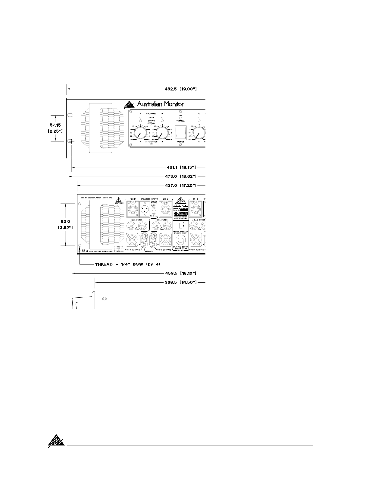
Front Panel
Figure 1 shows the panel layout of the AM1200. The
functionsofthecontrolsandindicatorsareasfollows:
1.Attenuator
Levelcontrol foryouramplifierisprovidedbya21
positiondetentedpotentiometerandindicatesgain
reduction in decibels from the 0 dB position
(maximumgain,noattenuation).
2. Status Indicator
ThisisadualcolourLEDwhichdisplaysthestatus
of the output stage and displays three levels of
operation.
Theselevelsare:
Below-20dB (unlit)
-20dBandabove (green)
1dBbelowactualclipping (red)
The LED will turn green once the output voltage
exceedsthe -20dBpoint (3.5volts).
The LED will change to red once the output ex-
ceeds the -1dB point before actual clipping of the
amplifier’soutputstage.Thethresholdofthe-1dB
point is referred to the amplifier supply rails and
alterswith changes in the mainssupply, changes
in the load and duty cycle fluctuations.
Theattackanddecaytime(ballistics),ofthestatus
circuit are those of a Peak Programme Meter
(P.P.M.)
NOTE:Theamplifierisnotdamagedbyrunninginto
clipping,butspeakersmaybe.Tomaximisethelife
of your speakers, try to keep clipping infrequent.
3. Fault Indicator
ThisamberLEDwillilluminatewhenafaultcondition
exists.
The fault detection circuit monitors the difference
betweendriveandoutputinyouramplifier.
Ifyouhaveashortonthespeakeroutput(orablown
negativerailfuse)theLEDwillflashbrightlyinsync
with the programme. This LED will also flash with
programmepeaksforgrossoverloadsoriftheload
is 2 ohms or less.
The circuit has two stages of operation:
1.Itwillprovideindication(e.g.grossoverload)but
does not affect the input signal (a faint flash).
2. It will indicate and mute the input signal (e.g.
shorted output) (brightly flashing or permanently
on).
4. Power Switch
PresstheswitchDOWNfor powerON and UP for
power OFF. At start-up (turn-on) the input to the
amplifier is muted by 30dB for approximately two
seconds.
5. On / Thermal Indicator
Whenswitching theamplifier on, thisred LEDwill
momentarilyflashRed,indicatingcorrectoperation
oftheMainsIn-RushCurrentSuppressioncircuit.
After establishment of the Inrush Current
SuppressioncircuittheLEDwill change to Green
indicatingtheunitisonandreceivingmainspower.
In the advent of a thermal overload this LED will
illuminateredindicatingthattheinternaloperating
temperature of one or all amplifier channels has
exceededasafelevelofoperationandthe amplifier
willbeshutdown.Thefanswillcontinuetorunand
oncetheamplifierhascooleddownsufficiently,the
amplifierwillstartupautomaticallyprovidingInrush
CurrentSuppressionandinputsignalmutinguntil
establishment of the amplifier after which it will
returntonormaloperatingmode.
NOTE:Youshouldalwaysensurethatthefangrille
iskeptcleanandfreefromthebuildupofdustand
lint.Thiswillensurelongeroperationofyouramplifier
and reduce the possibility of it prematurely going
intothermalshutdownmode.
6. Bridge Mode Indicator
This LED will illuminate yellow when the relative
pairsofchannelsoftheamplifierhavebeenselected
tooperateina "BRIDGE"modeofoperation.
Selection of the bridge mode is accomplished by
engagingtherearpanel"PUSHTOBRIDGE"Switch.
See section 5 (page 15) for more information on
Bridgemodeoperation.
Controls & Connectors 7