Dea Green Energy kit Product manual

GREEN
ENERGY KIT
Kit pannello solare
Istruzioni d’uso ed avvertenze
Solar panel kit
Operating instructions and warnings
Kit panneau solaire
Notice d’emploi et avertissements
Kit panel solar
Instrucciones de uso y advertencias
Kit de painel solar
Instruções para utilização e advertências
Zestaw zasilania energiąsłoneczną
Instrukcja montażu i użytkowania
I81003 Rev. 05 (28-11-2022)

GREEN ENERGY
7
EN
GREEN ENERGY
Solar panel kit
Instructions and warnings
Index
1Warnings Summary 75Installation and Assembly 10
2Product Description 86Electrical connections 11
3Technical data 87Maintenance 12
4Limits 88Product disposal 12
1 WARNINGS SUMMARY
WARNING! IMPORTANT SAFETY INSTRUCTIONS. CAREFULLY READ AND FOLLOW ALL WARNINGS AND INSTRUC-
TIONS THAT ACCOMPANY THE PRODUCT SINCE INCORRECT INSTALLATION COULD CAUSE HARM TO PEOPLE, ANIMALS
OR OBJECTS. WARNINGS AND INSTRUCTIONS PROVIDE IMPORTANT INFORMATION REGARDING SAFETY, INSTALLA-
TION, USE AND MAINTENANCE. KEEP THE INSTRUCTIONS TOGETHER WITH THE TECHNICAL DOCUMENTATION AND FOR
FUTURE REFERENCE.
WARNING Do not allow children to play with the appliance. The device may be used
by children of not less than 8 years of age, people with reduced physical, mental or
sensory impairment, or generally anyone without experience or, in any case, the required
experience provided the device is used under surveillance or that users have received
proper training on safe use of the device and are aware of the dangers related to its use.
WARNING All installation, maintenance, cleaning or repair operations on any part of
the system must be performed exclusively by qualified personnel with the power
supply disconnected working in strict compliance with the electrical standards and
regulations in force in the nation of installation.
Cleaning and maintenance destined to be performed by the user must not be performed
by unsupervised children.
WARNING Under no circumstances use the device in an explosive atmosphere or in
areas that may be corrosive or could damage product parts. Check that the
temperatures at the installation site are suitable and comply with the temperatures
declared on the product label.
WARNING In compliance with EU Directive 2012/19/EG on waste electrical and electronic
equipment (WEEE), this electrical product should not be treated as municipal mixed
waste. Please dispose of the product and bring it to the collection for an appropriate local
municipal recycling.
EVERYTHING THAT IS NOT EXPRESSLY PROVIDED FOR IN THE INSTALLATION MANUAL IS NOT ALLOWED. CORRECT
OPERATOR OPERATION IS ONLY ENSURED WHEN THE REPORTED DATA IS RESPECTED. THE COMPANY DOES NOT
TAKE RESPONSIBILITY FOR DAMAGE CAUSED BY FAILURE TO COMPLY WITH THE INSTRUCTIONS CONTAINED IN THIS
MANUAL. WITHOUT AFFECTING THE ESSENTIAL FEATURES OF THE PRODUCT, THE COMPANY RESERVES THE RIGHT
TO MAKE ANY CHANGES DEEMED APPROPRIATE AND AT ANY TIME IN ORDER TO TECHNICALLY, STRUCTURALLY AND
COMMERCIALLY IMPROVE THE PRODUCT WITHOUT BEING REQUIRED TO UPDATE THIS DOCUMENT.

GREEN ENERGY
8
2 PRODUCT DESCRIPTION
Green Energy is a solar power device for DEA System automatic gate operators. The panel converts solar energy into electrical energy, sto-
red in the accumulator. This provides power to the installation at any time of day (or night), including bad weather; it is particularly suitable
for automation located away from the fixed electricity.
The Green Energy kit consists of:
• n°1 Energy accumulator consisting of 2 rechargeable batteries and a 12V Solar Battery Charger PCB.
Inspect the contents of the package by comparing Fig. 1;
• n°1 Battery charger (art. Charger).
3 TECHNICAL DATA
ACCUMULATOR
Rated voltage 24 V
Maximum sink current 10 A
Battery capacity 18 Ah
Protection degree IP44
Operating temperature (°C) -20°C ÷ +50°C
Complete recharge time About 24 hours (by using fixed power supply)
Dimensions 585 x 245 x 185
Weight 16 Kg
PANEL (not supplied)
Rated voltage 24 V
Peak power 30 Wp
Operating temperature (°C) -40°C ÷ +85°C
Dimensions 660 x 390 x 25
Weight 3,7 Kg
4 LIMITS
Before installing Green Energy determine the actual installation power supply possibility. Then proceed taking into account the following
constraints:
• Ensure that the space surrounding the installation is sufficient;
• Consider the maximum length of the photovoltaic panel power supply cable panel (4 m) and the power supply cable of the automation
(4 m);
• Identify an area constantly illuminated by the sun all day long and all year round;
• Ensure that the area chosen for the assembly is in a location protected from impact damage;
• Make sure the surface chosen for the installation is made of solid material to ensure a stable fixation;
• The selected area should be away from vegetation, walls or other obstacles that could cast a shadow on the sensitive surface of the
photovoltaic panel;
Warning: Partial shade (also small), significantly reduces the energy capacity of the panel.
• Keep small distances between the accumulator and the operator to optimize the performance and durability;
• Adequately protect the battery from both high and low temperatures.
The battery tends to reduce significantly the yield at low temperatures while on the other hand, accelerates the decay of the parts at
high temperatures.
• Check the maximum number of operations/day executable, using the following formula:
Operations/day
where:

GREEN ENERGY
9
EN
Rggmm = Daily solar radiation - monthly average “expres-
sed in” Wh/m². “Indicates the amount of solar
radiation “available” in a day on average, in a
certain place. “Table 1” shows this value for lo-
cations located at a latitude of 45 degrees North
and 45° South, for each month of the year.
These values allow a rough calculation for other
latitudes. However, it is advisable to see the re-
lated “maps of solar radiation”, usually available
on the web, for places in very different latitudes
Table 1 “DAILY SOLAR RADIATION - MONTHLY AVERAGE” (Rggmm)
(Latitude 45°)
MONTH
(NORTH Emisphere)
Rggmm
“Wh/m²”
MONTH
(SUD Emisphere)
January 3034 July
February 3837 August
March 4703 September
April 4972 October
May 5268 November
June 5456 December
July 5616 January
August 5268 February
September 4750 March
October 3729 April
November 2993 May
Dicember 2314 June
I = Total current drawn by the installation expressed
in “A”. “Table 2” shows the approximate values
of absorption for each DEA System operator and
for accessories commonly used in a standard
installation.
Table 2 “OPERATORS ABSORPTION VALUES
FOR A TYPICAL INSTALLATION”
OPERATOR
ABSORPTION (A)
Gate loading
Minimum Medium Maximum
LIVI 6/24N 1,5 3 4,5
LIVI 9/24N 246
REV 24 2,5 3,5 5
902/24 1,5 3 5
LOOK - MAC - STING 0,8 2 3,5
GHOST/24 1,5 3 6
500 - 502 1 2,5 5
ANGOLO - GEKO 0,8 2 3
PASS N 24 2,5 3 3,5
STOP N 24 2,5 3,5 5
ACCESSORIES
MINILUX - 104 - 105 0,04
LINEAR 0,05
AURA N 0,1
t = Manoeuvres total time, expressed in seconds (s).

GREEN ENERGY
10
Example:
Automation for a swing gate with control panel art. NET24N based in Vicenza (latitude 45° 32’)
• 2 x LOOK operators;
• 1 pair of photocells art. LINEAR
• 1 flashing light art. AURA N
• leaf weight: medium
• period considered: April
N° operations/day
(from Table 1)
(from Table 2)
If the number of operations is not sufficient, you can connect the accumulator to one or more additional panels (up to 2 max). The various
panels will be connected in parallel using the “diode” provided.
In this case, the calculation of the number of operations must be carried out by multiplying the value of RGGMM by the number of panels
used.
5 INSTALLATION AND ASSEMBLY
For a satisfactory installation of the product is important:
• Define the correct orientation of the panel on the horizontal plane according to the following assessments:
a) For countries at NORTH of the equator , panel should be oriented exactly at SOUTH;
b) For countries at SOUTH of the equator the panel should be oriented exactly at NORTH;
• Determine the correct angle on the vertical plane of the panel according to the following assessments:
To obtain maximum efficiency from the solar panel when daylight hours are less (winter), you must tilt the cover so that the sun’s rays
hit the same perpendicular. Tilt the panel by an amount equal to the degree of the latitude of the place designated for the assembly (the
value can be obtained at any map).
Example: Madrid = 40 ° - Milan = 45 ° - London = 51 ° (see Picture 3).
Defined and satisfied these prerequisites, proceed to the assembly:
FIXING OF SOLAR PANEL (Pic. 2)
• Assemble the side brackets;
• Install the support bracket without tightening the screws;
• Fix the support bracket in the installation place, making sure to have appropriate channels;
• Tilt the panel according to estimates previously made;
ACCUMULATOR MOUNTING
• Mount the omega to the wall in a position close to the automation to be powered (Pic. 4);
• Hook the battery to the omega.

GREEN ENERGY
11
EN
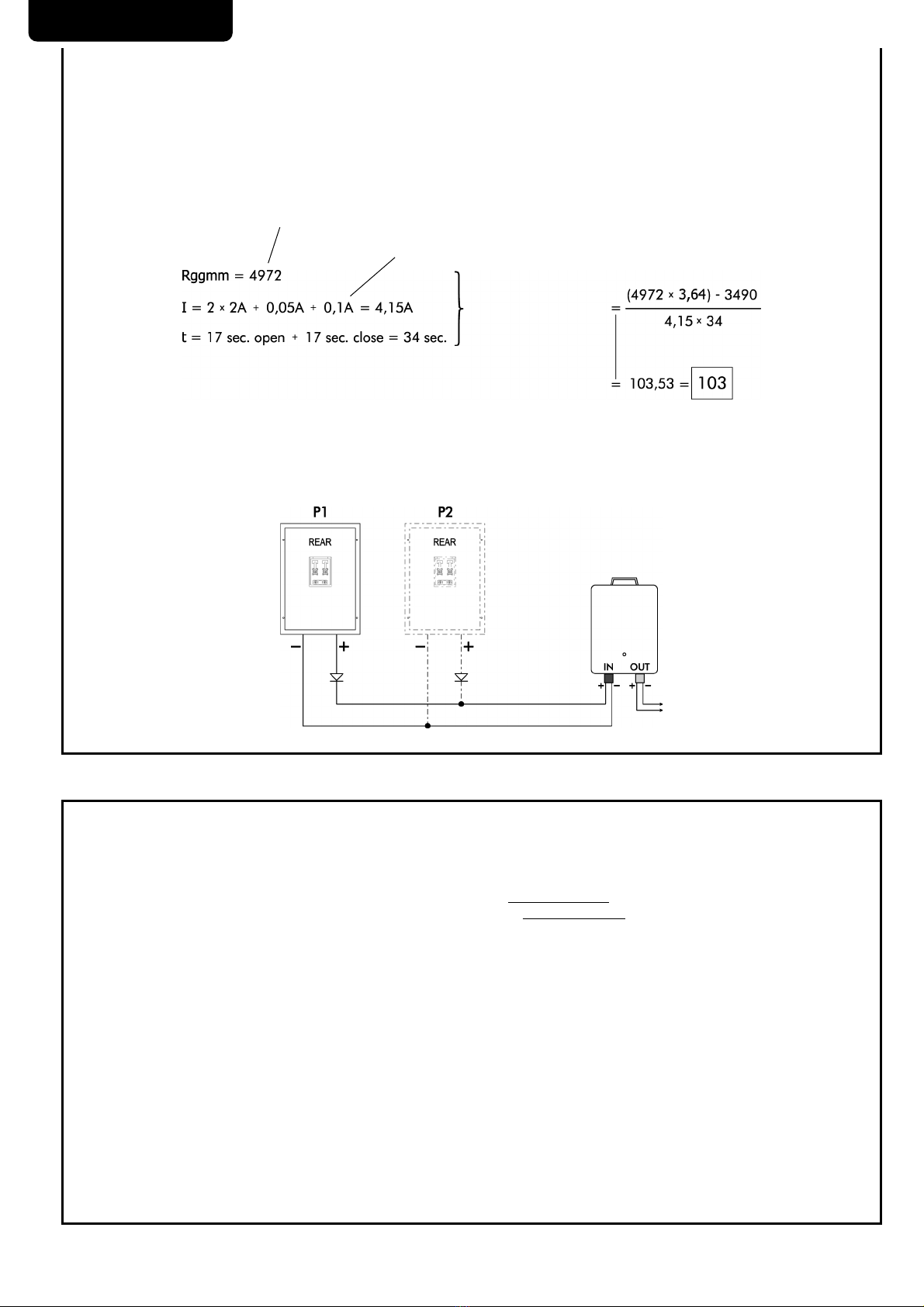
6 ELECTRICAL CONNECTIONS
WARNING Wire the photocells of the plant as shown and make sure that parameter P061 (for NET series boards) or EX.10 (for
EVO series boards) is set to 001.
If used with other control boards, it could not grant an adequate number of cycles.
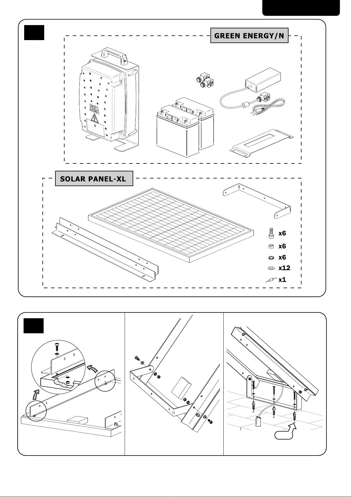
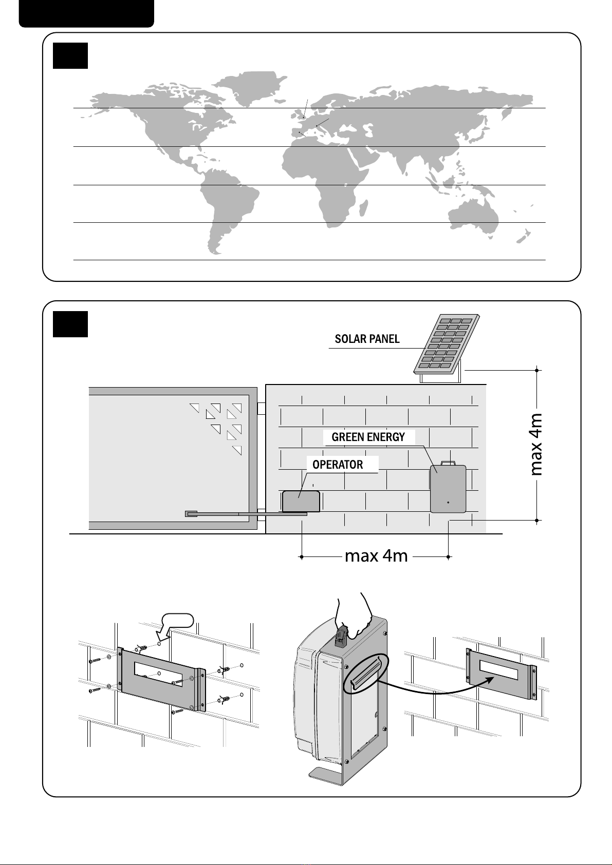
After attaching the panel and the battery, you will need to continue passing the panel cable (External standard 2x1mm² cable not sup-
plied. See Pic. 10) through the stem of protection to the accumulator. Similarly, you will have to pass the automation power cable (Art
CA/24 not supplied) to the accumulator by forcing it through any channel or conduit.
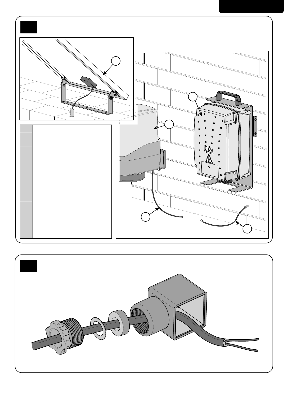
Passed the cables, you should proceed with the installation of the “L socket” in this way:
• Check that the cables length is adequate. If too long, adjust them;
• Insert the “L socket” components inside the cable as shown on Picture 6;
• Wire connectors (BLACK for the panel (Pic. 7.a) and GRAY for the operator (Pic. 7.b)) paying attention to polarity. The black connector
has a jumper that must NOT be removed;
• Finally, place the sealing ring on the connector and tighten the connector clamp.
After this, first connect the BLACK connector to the “IN” socket on the accumulator, securing it with the supplied screw and only then con-
nect the GREY connector to the “OUT” socket on the accumulator and secure it with the screw included (Pic. 9).
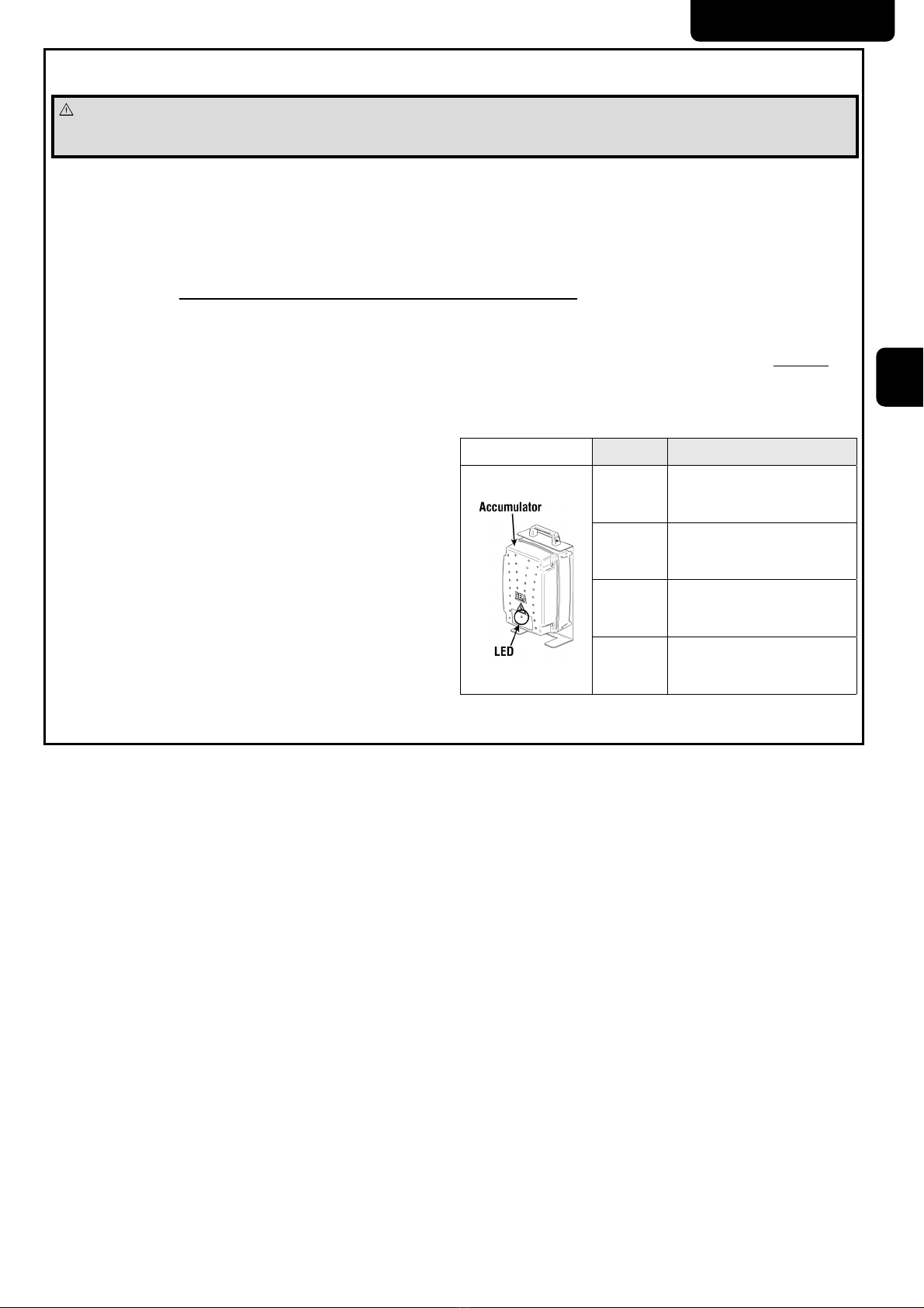
To avoid self-discharge of the accumulator, if the same is not con-
nected to solar panel, the output is automatically disconnected and
is therefore not possible to connect any load. In this case the LED
is off.
If the LED should remain off even after the connection to the solar
panel, this indicates that the battery is fully discharged (this condi-
tion is due to the long time in storage batteries).
In this case, you can:
• Wait until the panel charges the battery (the output is automa-
tically reconnected once achieved the required charge level for the
correct operation of the installation);
• Make a fast recharge by connecting the AC char-
ger (art. Charger) to the black connector “IN”. Wait
for the message fully charged battery (1 flash).
It is however advisable to perform a full charge before the installa-
tion in such a way as to ensure maximum efficiency.
Warning: If the batteries are very low, the LED on the accumulator
remains off until the battery voltage reaches the threshold for mini-
mum voltage to activate the electronic circuits.
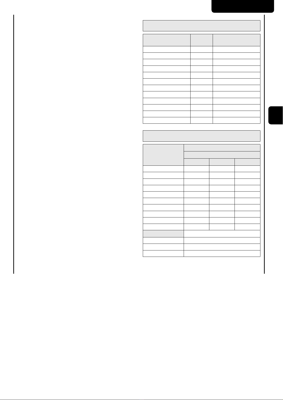
LED Battery status
Off Batteries fully discharged or con-
nector “IN” unplugged
3
Flashes
Battery discharged. The output
maybe disconnected automatically
2
Flashes Sufficient battery
1
Flashes Fully charged batteries

GREEN ENERGY
12
7 MAINTENANCE
The Green Energy photovoltaic panel requires no special precautions, you need to check its good condition and clean the surface. To ensu-
re an adequate level of efficiency, it is advisable to make such inspections at intervals not exceeding 6 months.
Replace the battery when, due to aging, does not guarantee the proper autonomy of the system.
In case of failure you can refer to the table “TROUBLESHOOTING GUIDE”. If the advice given does not lead to the solution contacting DEA
System.
TROUBLESHOOTING GUIDE
Description Possible solution
The control panel does not turn on
- The operator is not properly fed, check the connections and the conditions of the
power cable and eventually provide for their replacement / repair.
- Check that the battery charge level is sufficient to power the installation. If the
battery is fully discharged, make a quick charge using art. Charger or wait until the
panel charged the battery enough.
Batteries discharge too fast
- Check the good condition of the accumulator and if necessary replace it.
- Check that the number of operations performed by the installation per day falls
in the value given by the formula for the calculation of cycles in Chapter 3.
Batteries don’t charge
- Check the photovoltaic panel is correctly installed.
- Check the connections and conditions of the power cable and eventually provide
for their replacement / repair.
- Check the good condition of the accumulator and if necessary replace it.
8 PRODUCT DISPOSAL
Green Energy is composed of materials of different types, some of these can be recycled, others will be discarded.
Proceed as follows:
• Remove the accessory from the power supply and disassembly in reverse order from that described in “Installation”;
• Remove the electronic components;
• Sorting and disposing of various materials in strict accordance with the rules in force in the Country of sale.
WARNING In line with EU Directive 2012/19/EG for waste electrical and electronic equipment (WEEE), this electrical product must
not be disposed of as unsorted municipal waste. Please dispose of this product by returning it to your local municipal collection
point for recycling.

GREEN ENERGY
37
1
3x Ø6
2

GREEN ENERGY
38
0°
30°
60°
30°
60°
0°
30°
60°
30°
60°
51° (London)
40° (Madrid)
45° (Milan)
3
4x Ø6
4

GREEN ENERGY
39
5
2
3
4
1
1Pannello - Panel - Panneau - Painel
2Accumulatore - Accumulator - Accu-
mulateur - Acumulador - Akumulator
3
Motoriduttore - Operator - Moto-
réducteur - Motorreductor - Opera-
dor - Motoreduktor
4
Cavo alimentazione pannello - Pa-
nel power supply cable - Câble d’ali-
mentation panneau - Cable alimen-
tación panel - Cabo de alimentação
do painel solar - Przewód ]DVLODMĉF\
panel
5
Cavo alimentazione motoriduttore
- Operator power supply cable - Câ-
ble d’alimentation moto-réducteur
- Cable alimentación motorreductor
- Cabo de alimentação do operador
- PrzeZyG]DVLODMĉF\Potoreduktor
5
6

GREEN ENERGY
40
P2
P2. Punto di riferimento connettore
Reference point connector
Point de référence du connecteur
Punto de referencia conector
Ligador ponto de referencia
3XQNWRGQLHVLHQLD]áąF]D
8
OUT
IN
9
Spelare il cavo seguendo le misure dell’immagine
Split the cable according to the image size
Dénudez le câble en suivant les dimensions de l’image
Pelar el cable siguiendo la medida de la imagen
Dividir o cabo de acordo com o tamanho
3U]\VWRVRZDüSU]HZyG]JRGQLH]Z\PLDUDPL
podanymi na rysunku
-
+
P1
P1. Ponticello - Jumper - Pont - Puente
Jumper - Mostek
P2. Punto di riferimento connettore
Reference point connector
Point de référence du connecteur
Punto de referencia conector
Ligador ponto de referencia
3XQNWRGQLHVLHQLD]áąF]D
P2
7a
-
+
Spelare il cavo seguendo le misure dell’immagine
Split the cable according to the image size
Dénudez le câble en suivant les dimensions de l’image
Pelar el cable siguiendo la medida de la imagen
Dividir o cabo de acordo com o tamanho
3U]\VWRVRZDüSU]HZyG]JRGQLH]Z\PLDUDPL
podanymi na rysunku
P2. Punto di riferimento connettore
Reference point connector
Point de référence du connecteur
Punto de referencia conector
Ligador ponto de referencia
3XQNWRGQLHVLHQLD]áąF]D
P2
7b

GREEN ENERGY
41
Cablare le fotocellule dell'impianto come indicato e assicurarsi che il parametro P061 (per schede serie NET) o
EX.10 (per schede serie EVO) sia impostato a 001 - Wire the photocells of the plant as shown and make sure that
parameter P061 (for NET series boards) or EX.10 (for EVO series boards) is set to 001 - Câblez les photocellules
de l'installation comme indiqué et assurez-vous que le paramètre P061 (pour les cartes de la série NET) ou EX.10
(pour les cartes de la série EVO) est réglé sur 001 - Conecte las fotocélulas de la planta como se muestra y
asegúrese de que el parámetro P061 (para tarjetas de la serie NET) o EX.10 (para tarjetas de la serie EVO) esté
configurado en 001 - Conecte as fotocélulas da planta como mostrado e verifique se o parâmetro P061 (para
placas da série NET) ou EX.10 (para as placas da série EVO) está definido para 001 - 3RâĉF] fotokomórki
LQVWDODFMLWDNMDNSRND]DQRLXSHZQLMVLĘŮHSDUDPHWU3GODNDUWVHULL1(7OXE(;GODNDUWVHULL(92MHVW
ustawiony na 001.
Control Board 24V_ST
NET24N n°2
n°1
NET724N
NET724N XL
n°15
n°14
NET724 EVO n°10
n°11
11
1 2
3
10

EU Declaration of Conformity (DoC)
Company name: DEA SYSTEM S.p.A.
Postal address: Via Della Tecnica, 6
Postcode and City: 36013 Piovene Rocchette (VI) - ITALY
Telephone number: +39 0445 550789
declare that the DoC is issued under our sole responsibility and belongs to the following product:
Apparatus model/Product: GREEN ENERGY KIT
Type: Solar panel kit
Batch: See the label on the back of the user manual
The object of the declaration described above is in conformity with the relevant Union harmonisation legislation:
2011/65/EU (RoHS)
2014/30/EU (EMC)
2014/35/EU (LVD)
The following harmonised standards and technical specifications have been applied:
Title: Date of standard/specification
EN 63000 2018
EN 60335-1 2012 + AC:2014 + A11:2014 + A13:2017 + A1:2019 + A2:2019 + A14:2019
EN 61000-6-2 2005 + AC:2005
EN 61000-6-3 2007 + A1:2011 + AC:2012
EN 62233 2008
Additional information
Signed for and on behalf of:
Revision: Place and date of issue: Name, function, signature
00 Piovene Rocchette (VI)
25/11/2022
Tiziano Lievore
(Administrator)

DEA SYSTEM S.p.A.
Via Della Tecnica, 6 - 36013 PIOVENE ROCCHETTE (VI) - ITALY
tel: +39 0445 550789 - fax: +39 0445 550265
Internet: http:\\www.deasystem.com - E-mail: deasystem@deasystem.com
BATCH
Table of contents
Popular Solar Panel manuals by other brands

Grape Solar
Grape Solar CS-S-175-DJ Installation & user manual

solarwatt
solarwatt Panel vision AM 3.0 installation instructions

Nature Power
Nature Power 55120 user manual

Furrion
Furrion FURRIONNET-ZERO FSFP10MW-BL instruction manual

Improvements
Improvements 340029 quick guide

Energizer
Energizer HardCase Sunpack 80W user guide