auto maskin DCU 305 R3 LT User manual

Auto-Maskin
Installation Manual
DCU 305 R3
DCU 305 R3 LT
Diesel Engine Control Unit

About this manual •ii

Page 3 (44)
Content
Document information.........................................................................5
Introduction ..........................................................................................6
A
BOUT THIS MANUAL
.......................................................................................................................6
A
BOUT THE
DCU
305
R3
AND
DCU
305
R3
LT ...............................................................................6
C
LASSIFIED SYSTEM
.......................................................................................................................7
S
YSTEM
O
VERVIEW
........................................................................................................................8
C
ONFIGURATION OVERVIEW
.............................................................................................................9
T
ECHNICAL
S
PECIFICATIONS
............................................................................................................9
Cable connection ...............................................................................11
I
N GENERAL
.................................................................................................................................11
G
ROUNDING
................................................................................................................................11
C
ONNECTION ORDER
....................................................................................................................11
P
OWER SUPPLY
...........................................................................................................................13
S
TART
-
AND
S
TOP
R
ELAY
O
UTPUTS
...............................................................................................13
P
ICKUP SENSORS
.........................................................................................................................14
S
WITCH
I
NPUT
C
HANNELS
.............................................................................................................14
A
NALOGUE
I
NPUT
C
HANNELS
........................................................................................................16
J1939
CAN
CONNECTIONS
...........................................................................................................18
M
ISCELLANEOUS CONNECTIONS
.....................................................................................................20
T
HE AUTOMATIC FUSES ON THE
RK-66
MODULE
..............................................................................21
B
ACKUP SYSTEM CONFIGURATION
..................................................................................................22
B
UILT
-
IN
A
LARMS
.........................................................................................................................24
A
DJUSTING THE
LCD
SCREEN
.......................................................................................................25
O
VERSPEED TEST
........................................................................................................................26
Optional expansion modules ............................................................27
R
ELAY UNIT
MK-14 ......................................................................................................................27
A
NALOGUE UNIT
AK-6 ..................................................................................................................30
Communication ..................................................................................32
P
ROTOCOL AND PIN
-
CONFIGURATION
..............................................................................................32
M
ULTIDROP COMMUNICATION
........................................................................................................33
R
ETRIEVE THE LOG TO A
PC..........................................................................................................34
Schematic Drawings ..........................................................................35

Page 4 (44)
S
AMPLE
S
CHEMATIC
P
AGE
1 .........................................................................................................35
S
AMPLE
S
CHEMATIC
P
AGE
2 .........................................................................................................36
O
PTIONAL
R
ELAY
U
NIT
MK-14 ......................................................................................................37
O
PTIONAL
A
NALOGUE
U
NIT
AK-6 ..................................................................................................38
C
ABLE
S
PECIFICATION
..................................................................................................................38
Wire Terminal Tables .........................................................................40
RK-66
WIRE TERMINAL UNIT
..........................................................................................................40
R
ELAY UNIT
MK-14 ......................................................................................................................42
A
NALOGUE UNIT
AK-6 ..................................................................................................................43

Page 5 (44)
Document information
Document revisions
Date Revision
July 2005 Created
November 2007
July 2014
Minor adaptations for firmware 6.53 and onwards, because a new
menu layout.
DCU 305 R3 LT included, picture updates
Copyright © Auto-Maskin AS, 2014
Information given in this document may change without prior notice. This document
should not be copied without written permission from Auto-Maskin.
All trademarks acknowledged.
Related documents
DCU 305 R3 & R3 LT User’s Manual
DCU 305 R3 & R3 LT Communication Manual.
RSP 305 Remote Panel.
Rudolf R3 User’s Manual.
Rudolf R3 PC Configuration Software.

Page 6 (44)
Introduction
About this manual
This manual has been published primarily for professionals and
qualified personnel. A person using this material is assumed to have
basic knowledge in marine systems, and be able to carry out related
electrical work.
Work on the boats low-tension circuit should only be carried out by
qualified and experienced persons. Installation or work on the shore
power equipment must only be carried out by electricians authorised
to work with such installations.
It is the sole responsibility of the installer to ensure that the
installation work is carried out in a satisfactorily manner, that it is
operationally in good order, that the approved material and
accessories are used and that the installation meet all applicable rules
and regulations.
Note: Auto-Maskin continuously upgrades its products and reserves the
right to make changes and improvements without prior notice.
All information in this manual is based upon information at the time of
printing.
For updated information, please contact your dealer.
Assumptions
This document describes the DCU 305 R3 and DU 305 R3 LT, and it
will commonly be referred to as the DCU or the Control Unit.
When referring to voltages, we always assume DC-voltages. When
referring to AC-voltages it will be mentioned explicitly.
About the DCU 305 R3 and DCU 305 R3 LT
In general
The DCU 305 R3 is an electronic control unit for control and
monitoring of diesel engines used as propulsion engines or gensets.
Switches and senders from the engines are connected to the control
unit on the wire terminal card RK-66.

Page 7 (44)
The DCU 305 R3 can be connected directly to a printer for output of
all alarms and events, or it can be connected to a remote panel in a
network of control units.
Each project is unique, and the DCU 305 R3 is configured using a
configuration tool for Windows®, the Rudolf R3™ software.
DCU 305 R3 LT
The DCU 305 R3 LT is identical to the DCU 305 R3 with the
exception that the LT version is without CAN bus capability.
The DCU 305 R3 LT has the physical CAN bus port, but there is no
support for CAN bus internally.
Classified system
The DCU 305 R3 is classified by the following classification societies
with their respective certificate number as follows:
Classification Society Certificate Number
Det norske Veritas, DnV
Lloyd’s Register of Shipping, LR
Germanischer Lloyds, GL
Bureau Veritas, BV
Russian Maritime Register of Shipping, RS
Registro Italiano Navale, RINA
American Bureau of Shipping, ABS
Other certificates and approvals may exist.
Please see www.auto-maskin.com for latest update.
Page 8 (44)
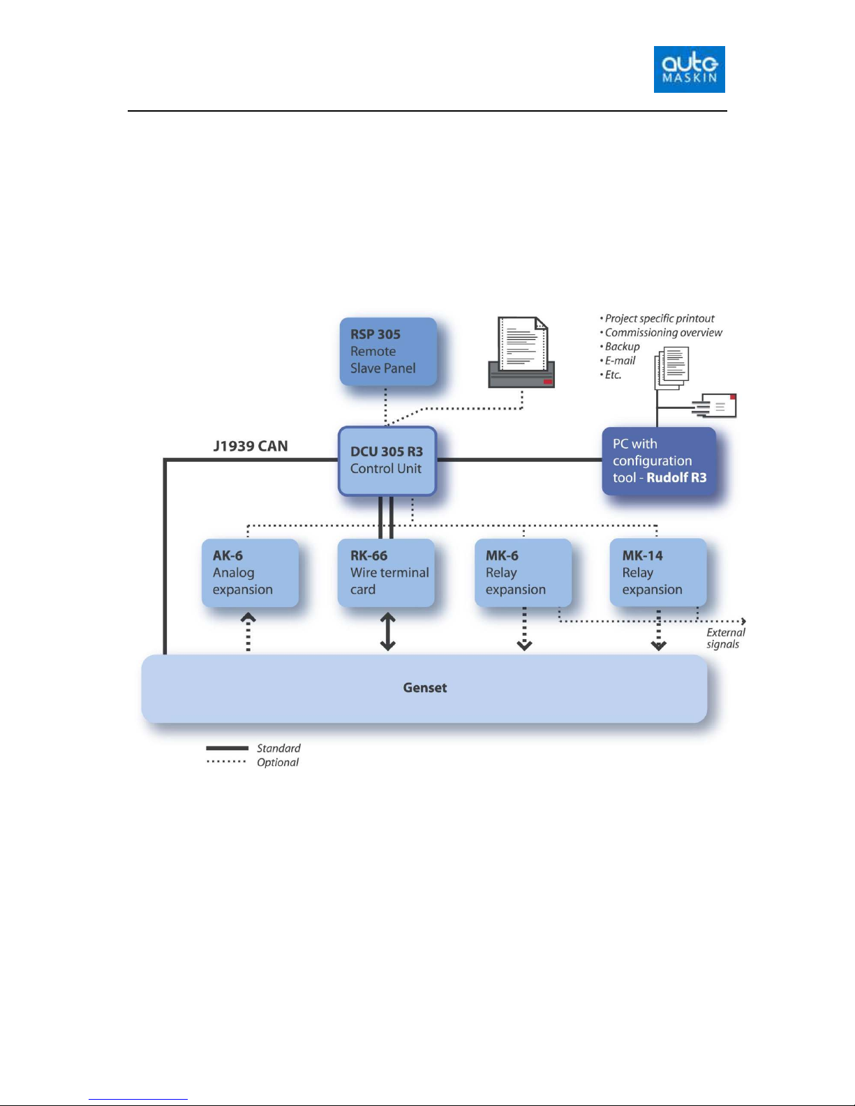
System Overview
The control unit and the wire terminal card with cables make a
complete genset monitoring system. Optional analogue cards and
relay cards may be added to further enhance the functionality and
flexibility.
The control unit is configured using a laptop PC with the
configuration software Rudolf™ installed. The configuration can be
printed and stored on disk.
Standard system
The DCU 305 and the RK-66 is part of the standard delivery that
makes a complete system. The other items are optional.
Remote panel
The optional RSP 305 Remote Panel can be added any time, as it
communicates directly towards the DCU 305 R3, and is self-
configuring.

Page 9 (44)
The RSP 305 Remote Panel configures itself automatically when
connected to one to four DCU 305 units, and as such requires no extra
configuration.
Configuration overview
The control unit is fully customised using the Rudolf™ configuration
program. For safety reasons, no parameters are adjustable without
using the configuration tool Rudolf.
No settings are necessary in the DCU 305 R3, nor in Rudolf, to
connect and use the Rudolf program. Just connect the cable between
your laptop PC and port P3 on the control unit.
Discussion of the Rudolf configuration software is beyond the scope
of this manual. For more information, please see the Rudolf R3 User’s
Manual.
Technical Specifications
Part Value
Overall dimensions (1) 160 x 260 x 35mm (6.3 x 10.2 x 1.4”) [H x W x D]
Cut-out dimensions 146 x 230mm (5.8 x 9.1”) [H x W]
Overall depth inc. cables 105mm
Supply voltage (2) 24V smoothed, (18– 32VDC)
Power consumption (3) Typical: 500mA @ 24V DC
Maximum: 700mA @ 24VDC
A PC with the Rudolf ™ parameter program is used to customize
the DCU 305 R3.

Page 10 (44)
Part Value
Weight Control unit: 1250g
Protection level Front panel:
Back panel:
IP54
IP30
Ambient temperature Operation:
Storage:
0-70°C
-20-70°C
Air humidity Operation:
Storage:
<90%
Dry
Analogue alarm latency Built-in
channels:
Expansion card
AK-6:
~1 sec
~5 sec
RK-66 relays
120VAC
24VDC
1A
1A
Notes
(1) The cables on the backpanel add to the overall depth.
(2) LCD backlight disappears if primary supply is below 18 volts, and
reappears when primary supply is above 20 volts.
(3) Display brightness full, 5 x 50% (12mA) analogue inputs.

Page 11 (44)
Cable connection
In general
To protect against EMC noise, we recommend that all cables are
shielded.
The shield of all cables shall be connected to ground, not to 0V!
Some cables are to be grounded in one end only, others in both ends.
Some cables shall be separate – for instance pickup signal and power
supply. Others signals can be in a multi-cable with shield.
See the example schematics and cable specification for details.
Grounding
Please keep ground and 0V separated!
Please observe the
difference between ground
and 0 volt!
Ground and 0V should not be connected together. In a ship installation,
the hull is the “ground” whilst the battery negative is the 0V.
In the DCU 305 R3 system, +24V and 0V are filtered to ground using
special filter components. This is done to avoid noise in the system. If
ground and 0V is connected together, these filters do not work properly.
In general, all switches should be referenced to 0V.
Connection order
All connections are made on the RK-66 terminal unit. The only
exception is communication cables, and analogue/relay expansion
cables, which are connected directly on the back-panel.
Start by connecting the ground cable to terminal 60 on the RK-66
terminal unit.
Note! Terminal 60 is connected to the ground plane (not to 0V) on
the RK-66 unit.
Page 12 (44)
The RK-66 wire terminal unit
Now, connect the rest of the wires and complete the installation by
connecting power to the supply inputs.
Terminals 1 and 2 are for the start battery supply, and terminals 3 and
4 are from the auxiliary supply.
Switch setting
By removing the rubber lid on the front of the RK-66, four dip-
switches numbered 1-4 will appear.
Switch Purpose Factory setting
1 When ON, start is enabled. This is the same as
connecting a jumper over terminals 39 and 40.
When OFF, no starts are possible!
A jumper between terminals 39 and 40 will
enable start.
ON
2 When ON, bypasses the return path diode to
start-battery negative (terminal 2), which in
some installations may reduce noise
interference.
Increases the measured battery voltage by 0.3V.
OFF
3 Noise filter between terminal 1 and 3 to ground.
Set the switch to ON to enable the filter.
OFF
4 Noise filter between terminal 2 and 4 to ground.
Set the switch to ON to enable the filter.
OFF
Connect the
two cables
between the
RK-66 and the
control unit.

Page 13 (44)
Power supply
24V supply
Use a twisted pair wire to minimize the effect of electrical
disturbances on the cable.
The start battery power shall be connected to terminals 1 and 2.
This is the primary supply.
The secondary (or auxiliary) supply shall be connected to terminal 3
and 4.
Note: In a classified system, a redundant supply must be connected to
terminals 3 and 4.
The control unit uses the highest voltage available from the two
supplies.
The primary voltage is constantly monitored and displayed on the
LCD. The control unit alarms if the primary supply is below the
configured value, or when the secondary supply is below 12V (fixed
setpoint).
The LCD light disappears if the primary voltage drops below 18V,
and reappear when the primary voltage rises above 20V.
12V supply installations
The DCU 305 R3 is a 24V system, but can be used in 12V systems
using an external DC/DC converter. The configuration in Rudolf must
be switched to fit a 12V system.
Connect the start battery to the primary input at terminal 1 and 2 as
above. This voltage is not high enough to make the control panel
work, but it measures the battery voltage.
Connect a 12/24V DC/DC converter to the 12V start battery, and
connect the 24V output to the secondary input, terminal 3 and 4.
Start- and Stop Relay Outputs
Connect auxiliary relays for Start (cranking), Stop, Run solenoid and
Shutdown solenoid.
Observe polarity if the relay coils are fitted with voltage suppressor
diodes.
Coil resistance on auxiliary relays must be in the range 250 ohm - 2
kohm.

Page 14 (44)
Pickup sensors
Connect the pickup 1 between terminal 5 and 6. Please verify that the
signal strength is between 2.5-30Vpp.
Note: The pickup cable must be shielded to ground, not to 0V.
Two pickups
If two pickups are being used, connect the second pickup to terminal
65 and 66. If the rpm differs >100rpm for 20 seconds, there will be an
alarm on the pickup with the lowest rpm.
The signal from pickup 1 has precedence, unless the frequency from
pickup 2 is >100rpm higher than pickup 1, where pickup 2 will be
used.
Note: Two Pickups must be enabled in Rudolf before it can be used.
Switch Input Channels
The control unit has 12 on/off input channels. All 12 channels can be
fully customised with text, delays and instructions to give a Warning,
Alarm or Shutdown.
Channel 1
2
3
4
5
6
7
8
9
10
11
12
Terminal # 7
8
9
10
11
12
13
14
15
16
17
18
Switch Input Channels and their corresponding wire terminal number on the RK-66
wire terminal card.
Inputs are connected to the Wire Terminal Card RK-66 as in the
above table.
The six first switch input channels can detect a broken wire situation,
and utilizes a backup system for shutdown purposes. See page 22 for
more information on the backup system.
Note: In a classified system, all shutdown switches must be connected to
switch inputs 1-6.
The following table illustrates the capabilities of the switch input
channels.

Page 15 (44)
Channel Broken Wire
Detection possibility
Backup on
Shutdown
channels
Warning, Alarm and
Shutdown possibility
1-6 Yes Yes Yes
7-12 No No Yes
Note: Do not connect +24V to the switch inputs! All input switches
must be connected via its corresponding wire terminal to 0V, not to
ground. Please see the schematic drawing page 35.
Connecting the Switches
Connect the warning, alarm and/or shutdown switches according to
the project documentation and drawings. All switches must be
connected between a wire terminal (7-18) and 0V.
An open (not connected) input is pulled ‘high’ internally. The
external switch must pull the input ‘low’ (0V).
Example: Switch channel 1 might be the Oil Pressure Low Shutdown.
The switch is then connected between Terminal 7 and 0V.
Wire break detection
Channel 1-6 has the ability to detect wire break. This is useful in
conjunction with the channel being used as a shutdown channel.
A 10k resistor (10 000 ohm) must be connected in parallel with the
switch. The resistor must withstand 1/8W (0.125W) or more.
Note: The Wire Break Detection feature must be enabled in Rudolf for
each of the channels 1
-
6 that are being used. Otherwise, there will not be
a Broken Wire alarm.
The control panel will now issue a “Broken Wire” alarm if the wire
into the control panel is broken. The alarm is delayed 5 seconds (fixed
time).
An alarm is displayed as:
* Broken Wire [T9]
Here, there is a broken wire on T9, terminal 9. Terminal 9 is switch
channel 3.
Considerations when using wire break detection
Make sure the return-path from the switch is connected to 0V
(terminal 29) at the connection card RK-66, not at the engine

Page 16 (44)
Example: a wire break detection installation on switch channel 1
should have a switch connected between terminal 7 (channel 1) and
terminal 29 (0V reference)
The 10k resistor must be connected across the switch, not across the
terminals 7 and 29.
Analogue Input Channels
The control unit has five industrial-standard 4-20mA inputs. These
may or may not be used, and – if used – are displayed on the LCD as
horizontal bars.
Note: An optional expansion card, the AK-6, is available to expand
the number of analogue inputs from 5 to 11. Please see page 27 for
details.
Using Rudolf, all 11 analogue channels can be configured as a 0
-
20mA or 4
-
20mA type.
Channel 1 can be configured as 0-10V.
Note: If channel 1 is used as 0-10V, use a separate shielded cable for
this signal as the 0-10V signal is highly susceptible to noise.
All analogue channels can be customised with text and delays and
whether to issue a Warning, Alarm or Shutdown.
Page 17 (44)
Note: Analogue channel one only, can be configured as a 0
-
10V
channel. The dipswitch J12 inside the unit must be set as follows:
0-20mA / 4-20mA
0-10V
Please note that this is applicable for analogue channel one only!
Default setting is 0
-
20mA / 4-20mA.
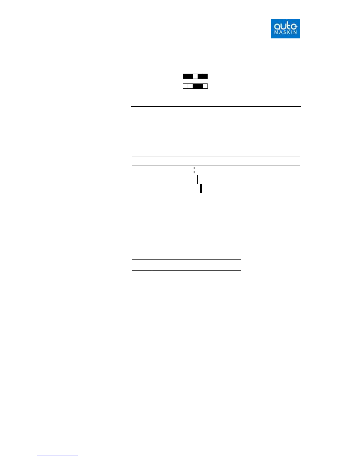
Analogue channel setpoints
In the display, the following markers are used to distinguish between
different types of setpoints:
None No setpoint
Warning Dashed line
Alarm Single line
Shutdown Double line
Analogue Sensor Failure
The alarm Analogue Sensor Failure appears if an enabled analogue
input is not connected, or if the signal strength is too low (<2mA).
Instead of a numeric value to the right of the bargraph, the sign “----“
will be displayed, for instance like this:
Oil Pressure OP1
---- Bar
Note! If 0-10V or 0-20mA is selected, the Analogue Sensor Failure
alarm will not appear.
Connecting the Analogue Sensors
Connect the sensors according to the project documentation and
drawings. All five analogue input channels are 0/4-20mA or 0-10V
(channel 1 only).
For PT100 and PT1000 sensors, an appropriate signal converter must
be used.

Page 18 (44)
RK-66 terminal number
Analogue
Channel
+24V supply to
sensor
Analogue input
1 19 20
2 21 22
3 23 24
4 25 26
5 27 28
Analogue Input Channels and the corresponding wire
terminal number on RK-66
Terminal 19, 21, 23, 25 and 27 are all +24V supply outputs. These
outputs are fused with a common, internal, automatic fuse (F3). The
fuse is located on the RK-66 card.
The fuse will automatically reset when the overload or short circuit is
removed. An alarm is given if the fuse blows and the alarm stays
activated as long as the short circuit is present.
For fuse sizes and characteristics, please see page 21.
Example: Analogue channel 1 might be the Oil Pressure sensor. The
sensor is then connected between terminal 19 (+24V supply) and
terminal 20 (4-20mA input).
J1939 CAN connections
The CAN bus cable
The CAN bus is a high speed data transmission network and requires
more from the cable installation than many other signal types.
The bus consists of two wires: CAN_H and CAN_L. Between units,
these wires should be connected CAN_H to CAN_H and CAN_L to
CAN_L, ie they should not be crossed.
Maximum cable length for the entire cable is 250m (820 feet).
The cable must be a twisted pair with shield. Minimum wire thickness
is 0.5mm^2 (20AWG) and maximum wire thickness is 0.8mm^2
(18AWG). The cable should be certified for CAN/J1939 use.
Minimum cable curve is 8x the cable diameter (ie it should not be
bent too sharp). It must not be deformed in any way.
On the DCU 305 R3 port P10, CAN_H is pin 7 and CAN_L is pin 2.
No other pins should be connected. The shield should normally be
connected at one end only, but in certain installations with a long
cable it may be favorable to connect it at both ends.

Page 19 (44)
Terminating Resistors
A CAN bus cable can connect many units. At each end of the bus, a
120ohm terminating resistor must be connected. If only two modules
are connected to the bus (which is common), each should have a
120ohm resistor connected at the end.
The DCU 305 R3 has a 120ohm resistor internally. If the DCU is not
at the end of the bus, a “CAN-card without J1” must be ordered and
fitted. Alternatively, the jumper J1 on the CAN-card can be removed
by competent personnel.
Note! The CAN bus might work even if there is a terminating resistor
too much or if one is missing, but it will not work if both terminating
resistors are missing.
If by accident, a 24VDC signal has been connected into the CAN bus,
the terminating resistor might be destroyed, and the CAN-card must
be sent in for repair.
Cable ducts
The CAN-cable can be strapped together with other communication
cables.
We recommend that the CAN-cable is not strapped together with
cables carrying high voltages, high currents, or cables connected to
inductive loads (power relays coil, electric engines, etc). Shielded
cables typically reduce the rub-off effect by 20dB, but do not remove
the problems completely.
In general, if the installation has cables carrying PWM-signals (high
frequency magnetic fields around the cable) for instance from a
frequency converter, these cables should be routed separately and in
good physical distance (5cm/2”) from parallel signal cables.
Distance between Engine ECM and DCU 305
If the CAN bus is routed to a different room/area on the ship that
might have a supply voltage different from the supply on the engine,
we strongly recommend using a CAN-repeater unit. The CAN-
repeater will be a galvanic isolation.
If using the same power supply as on the engine, a CAN-repeater is
not necessary.
The CAN bus in star network topologies
The CAN bus must not be connected in a star network. If this is
necessary, a CAN-repeater must be used. Maximum distance for the
branch is 30cm at 1Mbit/s.
The CAN-repeater and shield
When utilizing CAN-repeaters, the shields must not be connected
over to the new cable.

Page 20 (44)
Miscellaneous connections
Please also refer to the schematics, page 35, for the following
connections.
Remote Start
Remote Start works as the local Start Button.
Connect terminal 31 to terminal 30 to engage.
Remote Stop
Remote Stop works as the local Stop Button, except it is immediate
Connect terminal 32 to terminal 30 to engage.
Note: For safety reasons, local and remote Start and Stop works
regardless of the Manual and Standby setting.
Remote Reset (Acknowledge)
Connect terminal 37 to terminal 36 to activate Remote Reset.
This works as the local reset button on the front-panel, and reset all
the current alarms.
Blackout Start
When the control unit is set to Standby and receives this signal, it will
initiate the Automatic Start procedure. The number of start attempts is
configured in Rudolf.
Connect terminal 34 to terminal 33 to activate. See the schematics on
page 35.
When the engine has started, the signal can be removed. The engine
will not stop if the signal is removed.
Note: If Blackout Start and Delayed Stop are connected simultaneously,
Blackout Start is given priority.
The Delayed Stop signal has no effect if the Blackout Start signal is
present.
Delayed Stop
When the control unit receives the Delayed Stop signal, it will
disconnect the gen. breaker and run the genset for the predefined
cooling time before stopping.
Connect terminal 35 to terminal 33 to engage. Also, see schematic
page 35.
This manual suits for next models
1
Table of contents
Other auto maskin Control Unit manuals


