auto maskin Marine Pro DCU 210E User manual

Manual# 1006495
Installation Manual
200E Series
DCU 210E/208E –Engine Panel
RP 210E/220E –Remote Panel

Installation Manual
for the
Marine Pro 200E Series
~~~
DCU 210E/208E Diesel Engine Control Unit
RP 210E/220E Remote Panel
Revision
1.6
Revised
September 27, 2017
Revision history:
Rev.
Date
Description
1.0
2.9.2015
Initial release.
1.1
4.9.2015
Corrected thermistor terminals on page 6.
1.2
9.2.2016
Updated the connector pinout description page 6.
1.3
15.2.2016
Added connections drawing page 12.
1.4
18.3.2016
Thermistor 2, 3 and 4-wire drawings.
1.5
25.11.2016
RP 220E added.
1.6
25.09.2017
Added installation notes released to Ethernet and switches. Added
voltage sensor inputs. Updated to SW 3.6. Communication I/O link
updated.
Copyright © 2017 by Auto-Maskin AS.
All rights reserved. No part of this document may be reproduced or transmitted in any form or by any means,
electronic, mechanical, photocopying, recording, or otherwise, without the prior written permission of Auto-Maskin AS.

Installation Manual –200E Series Page iii
Table of Content
DOCUMENT INFORMATION ................................ 1
ABOUT THIS MANUAL .............................................. 1
Responsibilities .............................................. 1
MATCHING FIRMWARE ............................................ 1
ORDERING INFORMATION......................................... 1
OVERVIEW OF THE 200 SERIES .................................. 2
DCU 210E Engine Panel ................................. 2
DCU 208E Engine Panel ................................. 2
Configuration................................................. 2
RP 210E/220E Remote Panel......................... 2
Ethernet Switch ............................................. 3
Expansion ...................................................... 3
INSTALLATION..................................................... 4
PANEL LOCATION .................................................... 4
DCU 210E....................................................... 4
DCU 208E....................................................... 4
RP 210E/220E ................................................ 4
Compatible panel series ................................ 4
General .......................................................... 4
Panel Cut-out................................................. 5
Mounting bracket.......................................... 5
CONNECTORS......................................................... 5
Connector kit ................................................. 5
Connector pinout –DCU 210E and 208E ...... 6
Connector pinout –RP 210E/220E................ 7
WIRING CONNECTIONS ............................................ 8
General .......................................................... 8
Grounding...................................................... 8
Power Supply [C1P11 –C1P12]...................... 8
RIO Link [C1P5 –C1P6] .................................. 9
J1939 CANbus [C1P7 –C1P9 and C2P10 –
C2P11] ........................................................... 9
All Faults Relay [C2P1 –C2P3] ....................... 9
Relay #1 [C2P4 –C2P6].................................. 9
Relay #2 [C2P7 –C2P9].................................. 9
Magnetic Pickup, MPU [C4P1 –C4P2]........... 9
Modbus RS-485 [C4P3 –C4P5] ...................... 9
Thermistor Input [C4P6 –C4P11] ................ 10
Flexible I/O [I/O #1 –I/O #19] ..................... 10
Other Interfaces........................................... 11
FIRST POWER-ON................................................. 11
Preparations ................................................ 11
First Power-On Wizard ................................ 11
APPENDIX A....................................................... 12
Typical sensor connections DCU 210E ......... 12
Installation Manual –200E Series Page 1
Document
Information
About this manual
This manual has been published
primarily for professionals and
qualified personnel.
The user of this material is assumed to
have basic knowledge in marine
systems, and must be able to carry out
related electrical work.
Work on the low-voltage circuit should
only be carried out by qualified and
experienced personnel.
Installation or work on the shore
power equipment
must only
be carried
out by electricians authorized to work
with such installations.
Responsibilities
It is the
sole responsibility of the
installer
to ensure that the installation
work is carried out in a satisfactorily
manner, that it is operationally in good
order, that the approved material and
accessories are used and that the
installation meet all applicable rules
and regulations.
Note! Auto-Maskin continuously
upgrades its products and reserves the
right to make changes and
improvements without prior notice.
All information in this manual is based
upon information at the time of
printing.
For updated information, please
contact your local distributor.
Matching firmware
This Installation Manual is for the 200E
Series of panels.
It has been updated to match the
following firmware releases.
Panel
Firmware
Release
DCU 210E/ 208E
3.6
August 2017
RP 210E/220E
3.6
August 2017
Ordering information
The Marine Pro covers a wide range of
compatible products within both the
200- and 400 Series. Please visit our
web site for more information.
http://auto-maskin.com/marine/
Installation Manual –200E Series Page 2
Overview of the 200
series
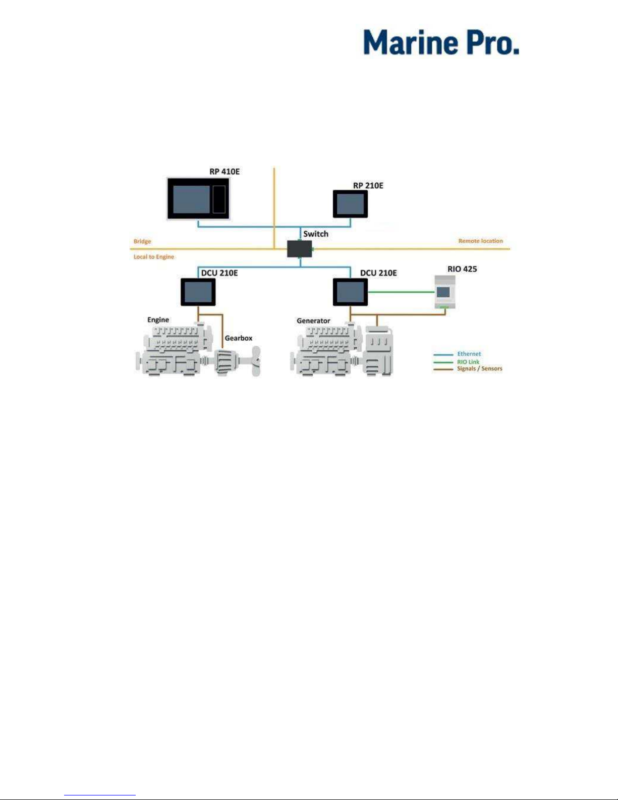
The drawing below shows a typical
layout.
DCU 210E Engine Panel
The DCU 210E engine panel is the
main building block in the 200 Series.
Engine sensor values are displayed on
the color touch screen, and commands
and other user interaction is also here.
DCU 208E Engine Panel
The DCU 208E is basically the same as
the DCU 210E, but without the color
touch screen.
It saves cost being used in smaller
engine rooms, where a remote panel is
all that is needed.
Configuration
An ordinary PC web-browser is used
to configure the DCU, using the inbuilt
web-server on the DCU.
RP 210E/220E Remote Panel
The optional RP remote panel brings
everything on the DCU to a remote
location, with the exact same user
interface. It does not need any
configuration, as it is reading the
configuration from the DCU.

Installation Manual –200E Series Page 3
As such, the RP can easily be
retrofitted.
The RP also supports one IP-camera to
be installed on the network.
Ethernet Switch
The Ethernet switch is not necessary if
only one DCU 210E and one RP
210E/220E is in use. These can then
be wired with an Ethernet cable
directly.
It is recommended to make use of an
Ethernet switch though, as it simplifies
PC configuration connection and
future expansion to remote panels
and/or camera interface.
Note! For redundant Ethernet
connection,
managed
Ethernet
switches must be used.
Expansion
The basic system can be expanded
with more input and output channels
using the versatile RIO units (Remote
I/O).
Currently, there are RIO units for
I/O expansion, RIO 410 and RIO
210.
Exhaust temperature
monitoring, RIO 412
Generator monitoring, RIO 425
Load sharing, LSU 408

Installation Manual –200E Series Page 4
Installation
Installation covers panel location,
wiring and first power-on.
Panel location
This section gives basic guidelines for
installing the different panels.
DCU 210E
The panel is normally located in the
engine room for a number of reasons.
The main reasons are:
Local operation and overview.
Minimize cabling requirements
and cost from sensors to panel.
Reduce of electrical noise levels
resulting from long cables.
DCU 208E
This panel is also normally installed in
the engine room, close to the engine.
Unlike the DCU 210E and the RP
210E/220E the DCU 208E is installed
on a din-rail.
The panel does not have a user
interface and is normally used in
unmanned engine rooms.
A RP 210E/220E remote panel is used
to bring the signals from the engine
room to a monitoring site, e.g. bridge
or wheelhouse.
RP 210E/220E
The RP remote panel is normally
located at a remote place away from
the engine room, but it can also be
used in the engine room.
Compatible panel series
Note that the 200 series panel can be
used together with the 400 series
panels.
For instance can a RP 210E/220E
remote panel be used to monitor a
DCU 410 engine panel.
General
Panels with a screen should be
mounted at about eye level and the
user should have easy access to
operate the panel.
Ensure easy access to the rear wiring.
The panel may be mounted on the
engines supporting structure provided
shock absorbers are used either
between the structure and the engine,
or between the structure and the panel
enclosure.
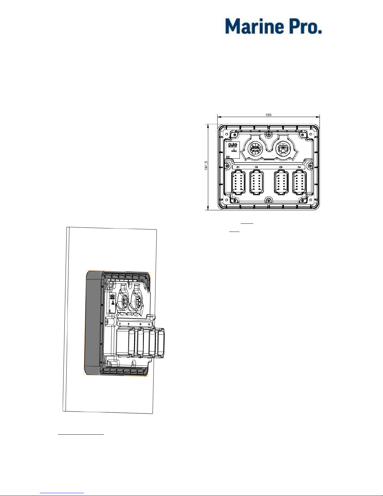
Installation Manual –200E Series Page 5
Panel Cut-out
The DCU and RP cut-out size is:
153mm width, 123 mm height
Mounting bracket
DCU 210E and RP 210E/220E
When installing the panel make sure to
use the bundled screws and mounting
bracket.
If installing the panel on a thicker
surface than 5mm, longer flanged
screws must be used. In this case M3
16mm flanged screws is
recommended.
Make sure that the screws are not too
long, as this will damage the panel.
The DCU 210E / RP 210E installed with the
mounting bracket shown in grey.
Connectors
DCU 210E, DCU 208E, RP 210E
and RP 220E
These are the connectors on the DCU
and RP back lid.
The DCU 208E front view is the same as the
DCU 210E rear view.
Connector kit
The 200E series is not shipped with
mating connectors.
A complete kit is available containing
all of the mating terminal blocks used
on the 200 E series.
Kit 1006479 contains:
4 Deutsch DT series connectors
(DT06-12SA).
50 hand crimp sockets 0.5 -1.0
mm2(16-20 AWG).
10 hand crimp sockets 1.0 -2.0
mm2(14-16 AWG).
50 sealing plugs for unused
terminals.
A crimp tool is necessary for
proper crimping of the mating
terminals. Use Deutsch HDT-48-00
crimping tool.

Installation Manual –200E Series Page 6
Connector pinout –
DCU 210E and 208E
The table below shows the connector
pinout on the DCU panels.
The connector is described as e.g.
C1P2. Where 1 is the connector
number and 2 is the pin number.
See Appendix A to see typical sensor
connections DCU 210E.
Power Supply
C1P11
+12/24VDC Primary Supply
In/Out
C1P12
0V Primary Supply
In
C1P3
Ground connection
In
RIO Link Interface
C1P5
Low
In
C1P6
High
In
CAN J1939 Engine Interface
C1P7
CAN 1High
In
C1P8
CAN 1 Low
In
C1P9
CAN 1 Shield
In
C2P10
CAN 2 High - (I/O #203)
In
C2P11
CAN 2 Low - (I/O #213)
In
C2P12
CAN 2 Shield - (I/O #5)
In
All Faults Relay (Inactive on fault)
C2P1
NC
-
C2P2
Common
-
C2P3
NO
-
On Board Relay #1
C2P4
NC
-
C2P5
Common
-
C2P6
NO
-
On Board Relay #2
C2P7
NC
-
C2P8
Common
-
C2P9
NO
-
Magnetic Pickup
C4P1
A
In
C4P2
B - (I/O #181)
In
Modbus RTU, RS-485
C4P3
Shield
In
C4P4
Low
In
C4P5
High
In
Thermistor Input
C4P6
Thermistor #1 A
In
C4P7
Thermistor #1 B
In
C4P8
Thermistor #1 C
In
C4P9
Thermistor #2 A
In
C4P10
Thermistor #2 B
In
C4P11
Thermistor #2 C
In
Flexible I/O
C1P1
I/O #1
In/Out
C1P2
I/O #21
In/Out
C1P4
I/O #3
In/Out
C1P10
I/O #4
In/Out
C2P12
I/O #51
In/Out
C3P1
I/O #62/ Sensor Power
In/Out
C3P2
I/O #7
In/Out
C3P3
I/O #8
In/Out
C3P4
I/O #9
In/Out
C3P5
I/O #10
In/Out
C3P6
I/O #11
In/Out
C3P7
I/O #121
In/Out
C3P8
I/O #13
In/Out
C3P9
I/O #14
In/Out
C3P10
I/O #15
In/Out
C3P11
I/O #16
In/Out
C3P12
I/O #17
In/Out
C4P2
I/O #181
In/Out
C4P12
I/O #19
In/Out
1Configurable as flexible I/O or as a 0V
reference.
2Configurable as flexible I/O or supply for 0-
5V sensors.
3Alternative I/O function is digital input only.

Installation Manual –200E Series Page 7
Connector pinout –
RP 210E/220E
The table below shows the connector
pinout on the RP panel.
The connector is described as e.g.
C1P2. Where 1 is the connector
number and 2 is the pin number.
Power Supply
C1P11
+12/24VDC Primary Supply
In/Out
C1P12
0V Primary Supply
In
C1P3
Ground connection
In
Switch Input
C1P1
Switch Input #1
In
C1P2
Switch Input #2
In
C1P4
Switch Input #3
In
All Faults Relay (Inactive on fault)
C2P1
NC
-
C2P2
Common
-
C2P3
NO
-

Installation Manual –200E Series Page 8
Wiring Connections
The following chapter primarily
assumes a DCU panel.
If installing an RP, then just disregard
descriptions that is not described in
the table “Connector Pinout RP
210E/220E”.
General
To protect against EMC noise, we
recommend that all cables are
shielded.
Note! The shield of all cables shall be
connected to ground/hull,
not
to 0V!
For good electrical noise separation,
consider routing some cables separate
from other cables –for instance the
pickup signal cable.
Note! Connect shield in one end of the
cable only.
Grounding
In marine installations, ground and 0V
volt should not be connected together.
In a ship installation, the hull is the
“ground” whilst the battery minus is
the 0V.
In the DCU system, +12/24V and 0V
are filtered to ground using special
filter components. This is done to
reduce electrical noise entering the
system.
Note! Please keep ground and 0V
separated!
If ground and 0V is connected, these
filters do not work properly.
Power Supply [C1P11 –C1P12]
The 200E Series is designed to run on
either 12 VDC or 24 VDC supply
voltage.
Note! Make sure the supply power is
sourced directly from the battery, and
not
from the starter engine, as the
voltage drop over the latter is
significant.
Power Supply Requirements
The panel must be sourced with an 8-
32VDC supply. This is the “full
functionality” range.
General
Use a cable with twisted pair wires to
minimize the effect of noise on the
supply input.
Connect the cable straight from the
battery and keep the cable as short as
possible.
Use at least 1.0mm2(17 AWG) wires
for the power supply.
12 V supply
If the supply voltage is in the range 8-
16V, then the panel automatically
assumes it is on a 12 VDC system.
24 V supply
If the supply voltage is in the range
16-32 V, then the panel automatically
assumes it is on a 24 VDC system.
Alarm for Low Power Supply
The input voltage is monitored with
fixed set points. The set points are as
follows:

Installation Manual –200E Series Page 9
24 V supply
Warning: <21 V
Alarm: <18 V
12 V supply
Warning: <11 V
Alarm: <10 V
The persistence timer is fixed for all
set points at 30 sec before a warning
or an alarm.
RIO Link [C1P5 –C1P6]
DCU 210E and 208E
This is the link for the optional
expansion units RIO 210, RIO 410, RIO
425 and LSU 410.
Shield the cable in the RIO end only.
RP 210E/220E
On these panels, the RIO link is used
for the optional ambient light sensor
ALS 210, which provides automatic
adjustment of the backlight intensity.
J1939 CANbus [C1P7 –C1P9 and
C2P10 –C2P11]
Engine J1939 CANbus interface for
connection to the engine ECM,
electronic control module.
All Faults Relay [C2P1 –C2P3]
Note that the relay is activated when
there are no faults, and deactivates for
any fault.
A “fault” is defined as any new
instance in the alarm list, except
diagnostic messages graded white.
The relay has a 1 A over-current
protection on the common pin.
Relay #1 [C2P4 –C2P6]
This relay can be configured to
activate for any inbuilt function.
See the configuration manual.
The relay has a 1 A over-current
protection on the common pin.
Relay #2 [C2P7 –C2P9]
This relay can be configured to
activate for any inbuilt function.
See the configuration manual.
The relay has a 1 A over-current
protection on the common pin.
Magnetic Pickup, MPU [C4P1 –
C4P2]
The engine speed pickup is connected
here.
Pickup must be of Magnetic (sine-
wave) or digital (square-wave) type.
Frequency range: 100 HZ –10 KHz.
Amplitude range: 2Vp-p –30Vp-p
Shield the cable at the pickup end
only.
Modbus RS-485 [C4P3 –C4P5]
The DCU has an inbuilt Modbus™
interface, both on RS-485 and also on
Ethernet. The latter is known as
Modbus TCP.
Addressing wise, these are equal, and
the complete I/O list is available online
here:
Installation Manual –200E Series Page 10
Communication list
(https://docs.google.com/spreadsheet
s/d/1yE8VU858j559lCNR-
3cQeg9R78ncSFoczq0p0T2rU6o)
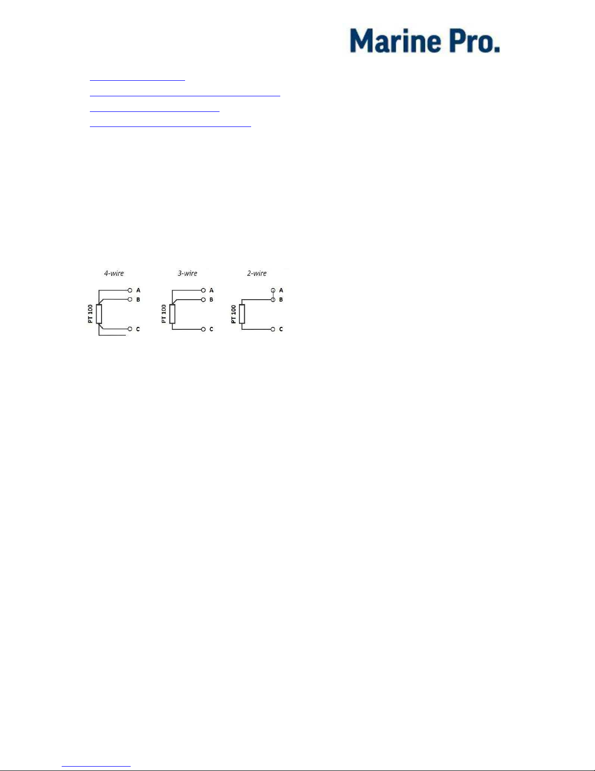
Thermistor Input [C4P6 –C4P11]
There are two thermistor input
channels on the DCU.
The channels support sensors with
two, three or four wires. See figure
below for recommended wiring
options.
Measurement range is 95 –60k ohm.
Detectable failure modes:
Broken wire between A/B and C
Short circuit between A/B and C.
Flexible I/O [I/O #1 –I/O #19]
There are nineteen Flexible I/O
channels on the DCU.
Each channel can be configured for
different use as described below.
Power Output
All flexible I/O can be configured as
12V 0,2A or 24V 0,2A power outputs
with short circuit detection and
protection.
Switched Output
All flexible I/O can be configured as
configurable 12/24V outputs on the
DCU.
Each channel can be configured for
any available function.
Voltage Sensor Input
All flexible I/O can be configured as
voltage sensor inputs on the DCU.
The voltage sensor input is capable of
measuring 0 –32 VDC.
Input impedance is 11kΩ.
4-20mA Input
All flexible I/O can be configured as
4-20 mA analog sensor inputs on the
DCU.
If the signal is out of range, a warning
will be displayed.
Out of range is defined as:
< 2 mA (broken wire)
> 22 mA (short circuit)
Note that the internal impedance is 50Ω.
Switched Input
All flexible I/O can be configured as
12/24 V input channels.
Each channel can be configured as an
engine switch, e.g. Oil Pressure Low
switch, or it can be configured to
activate an inbuilt function, eg.
Automatic Start.
Input impedance is 11kΩ.
Use the power supply voltage from
C1P11 or a configurable I/O set to
power output to power the switch
inputs.
See the Configuration manual for more
information.

Installation Manual –200E Series Page 11
Other Interfaces
Ethernet MODBUS/TCP
The DCU connects to a LAN (Local
Area Network) or directly to a PC
through a standard CAT-5 network
cable connected to the RJ45 port.
The IP address in the DCU and/or the
local PC may need to be changed in
order to access the DCU configuration
from a PC.
Note! Do not bend the Ethernet cable
or pull the cable sideways more than
necessary during installation.
Use a strain relief for the cable making
the cable length no more than 50 cm
between the connector and the strain
relief.
USB Memory Interface
This interface is used for two
purposes:
Update of the current
configuration file (not RP
panels).
Update the panel firmware (all
panels)
Copy a valid configuration and/or
firmware file to a USB memory stick,
and insert the USB memory stick in the
panel.
Follow the instructions that will be
appearing on the screen.
First Power-On
Preparations
First, make sure to consult the Quick
Installation Guide (QIG) that came with
the panel.
Installation
Install the panel according to
guidelines in the QIG.
Connections
Connect power to the panel according
to guidelines in the QIG.
First Power-On Wizard
The DCU (not DCU 208E) will display
the
first power-on wizard
at the first
power up after delivery, or after a
factory reset of the panel.
All wizard settings can be changed
later.

Installation Manual –200E Series Page 12
Appendix A
Typica l sensor connectio ns DCU 210E
This manual suits for next models
3
Table of contents
Other auto maskin Control Unit manuals


