Autocall 4010ES User manual
4010ES Automatic Extinguishing, Deluge and Preaction Sprinkler System Releasing
Control
* Additional listings may be applicable; contact your local Product supplier for the latest status.
UL, ULC Listed*
4010ES Fire Control Units
AC4010-0005 Rev. 10 5/2017
Features
Releasing control using the Autocall 4010ES Fire Alarm Control
Unit to provide:
• Coverage for multiple areas of Automatic Extinguishing Release and/
or Deluge and Preaction Sprinkler System Release including audible
escalation of events
• Control of compatible Listed/Approved 24 VDC automatic control
actuators, one per circuit; or two 12 VDC actuators in series per circuit
• Releasing appliance circuits (RACs) by connecting Notification appliance
circuits (NACs) to Suppression Release Peripherals for actuator
supervision and control
• Four, 3 Amp Notification Appliance Circuits (NACs) in the control unit
for use with Suppression Release Peripherals (SRP) and required
notification appliances
• Additional actuator circuit control and additional NACs are available
using 4009 IDNet Addressable NAC Extenders and Suppression
Release Peripherals
Audible Escalation of Events:
• Temporal or 20 bpm March Time pattern for first cross zone alarm
• 120 bpm March Time pattern indicates releasing timer active
• On steady indicates releasing timer expired and actuator is activated
• Requires NACs dedicated to conventional horn control (not SmartSync
operation) with strobes controlled on separate NACs
4009 IDNet NAC Extenders provide:
• Up to eight NACs for notification requirements and for NAC input to
Suppression Release Peripherals
• Control is via IDNet addressable communications
A4090-9005/A4090-9006 Suppression Release Peripheral (SRP)
with Dual Input Control Logic:
• Dual input control logic requires that both IDNet communications
commands and an activated NAC are present to initiate the desired
release
• Releasing Appliance Circuit (RAC) output provides wiring supervision
to the actuator including monitoring of coil continuity and short circuit
supervision to the coil supervision module
Suppression Release Peripheral control features:
• An on-board DC-DC regulator compensates for voltage drops to the
peripheral and ensures proper control circuit voltage over a wide
operating range
• Provides a single RAC for control of actuators for up to 2 A using a 3 A
NAC input (1 A using a 2 A NAC input)
Related system components
• 4010ES Series control unit with Releasing Appliqué
• Dedicated NAC output from 4010ES (or compatible NAC Extender)
• Coil supervision module, one per RAC
• Maintenance Switch, one per RAC
• Abort Switch connected via an addressable interface module
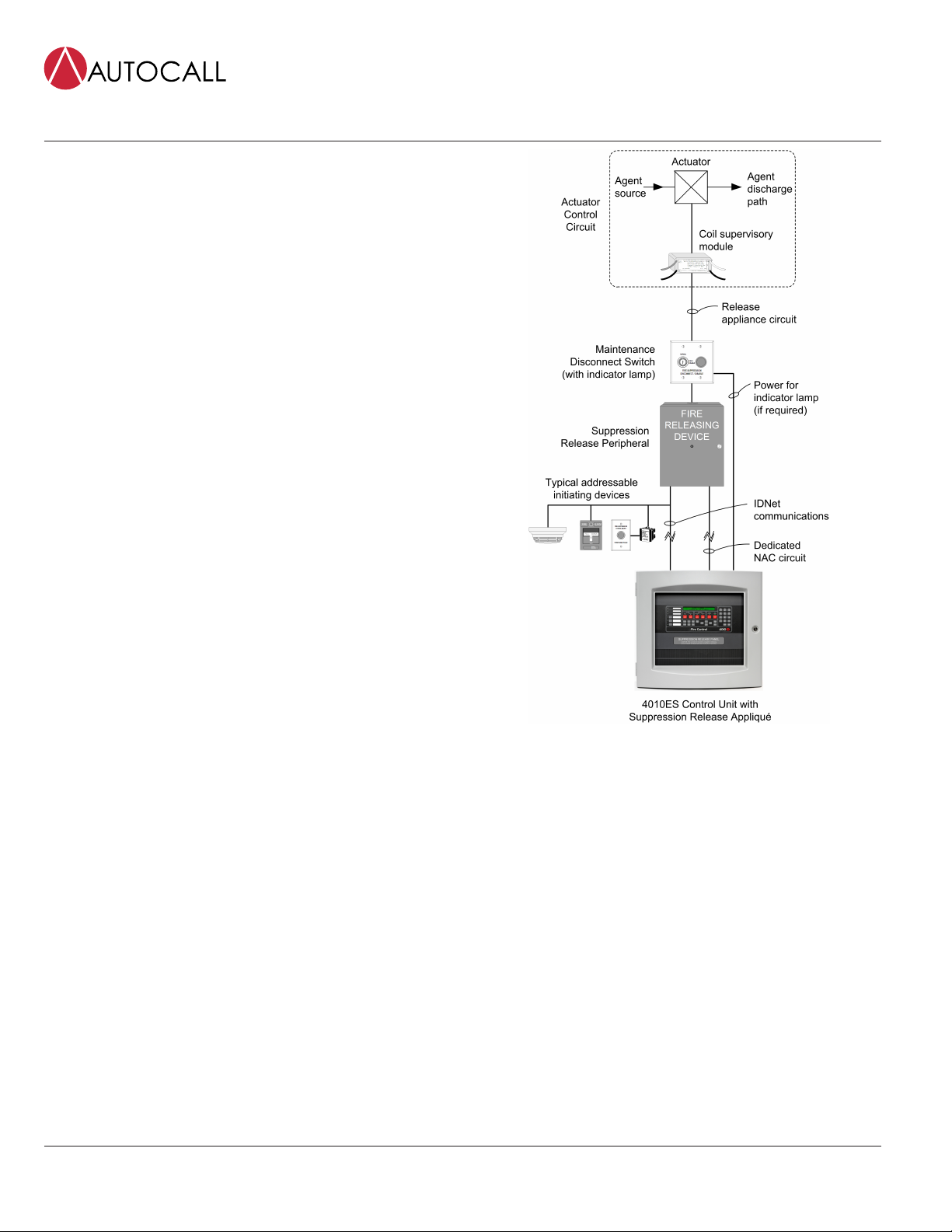
Figure 1: 4010ES Release Control
Simplified Block Diagram
Introduction
When combined with Suppression Release Peripherals, the 4010ES
series fire alarm control unit provides actuator supervision and control
for use in automatic extinguishing, and deluge or preaction releasing
systems. Hazard area initiating and notification devices are controlled
using either conventional or addressable circuits per standard 4010ES
capabilities. The necessary releasing system logic is implemented within
the 4010ES control unit as required for the local application.
Agency Listings
UL 864 - Control Units, System (UOJZ); Control Unit Accessories, System,
Fire Alarm (UOXX); Control Units, Releasing Device Service (SYZV); Smoke
Control System Equipment (UUKL)
UL 1076 - Proprietary Alarm Units (APOU)
UL 1730 - Smoke Detector Monitors and Accessories (UULH)
UL 2017 - Emergency Alarm System Control Units, CO detection (FSZI);
Process Equipment Management (QVAX)
ULC-S527 - Control Units, System, Fire Alarm (UOJZC); Control Unit
Accessories, System, Fire Alarm (UOXXC); Control Units, Releasing Device
Service (SYZVC); Smoke Control System Equipment (UUKLC)

4010ES Automatic Extinguishing, Deluge and Preaction Sprinkler System Releasing Control
Page 2 AC4010-0005 Rev. 10 5/2017
ULC-S559 - Central Station Fire Alarm System Units (DAYRC)
ULC/ORD-C1076 - Proprietary Burglar Alarm System Units (APOUC)
ULC/ORD-C100 - Smoke Control System Equipment, UUKLC
Automatic Extinguishing Release Systems
These systems automatically activate electrically controlled actuators
for the release of a fire extinguishing agent (such as dry chemical, water
spray, foam, CO2, or clean agent) in response to fire detection device
inputs as determined by programming of the host fire alarm control unit.
Automatic Extinguishing Release Systems are required to have a
minimum of 24 hours of standby power. Initiating devices must be
Listed/Approved for the application, and may be wired either Class A
or B. Control actuators must be electrically compatible with the control
unit circuits and power supplies, and are wired Class B to provide coil
supervision.
Deluge or Preaction Sprinkler Systems
These systems automatically activate water control actuators in
response to fire detection device inputs.
Deluge Sprinkler Systems employ open sprinkler heads and provide
water flow when the fire detection system activates a common
automatic water control actuator. They are used to deliver water
simultaneously through all of the system sprinkler heads. This type of
system is applicable where the immediate application of large quantities
of water over large areas is the proper fire response.
Preaction Sprinkler Systems are similar to deluge systems except
that normally closed sprinkler heads are used and supervisory air
pressure is maintained in the pipe. Operation requires both an activated
sprinkler head and an activated fire alarm initiating device with specific
programming determined at the host fire alarm control unit.
Releasing System Requirements
Releasing actuators are controlled from a Suppression Release
Peripheral (A4090-9005 or A4090-9006). Connections are 2-wire, Class
B releasing circuits with only one 24 VDC actuator per circuit. Where
applicable, two, 12 VDC actuators in series, or one 12 VDC actuator with
manufacturer supplied resistor may be used.
1. Coil Supervision Module A2081-9046 must be wired electrically
before the actuator and located in the actuator wiring junction box.
The connected RAC provides continuity supervision of the actuator
coil and wiring and provides short circuit supervision to the coil
supervision module.
2. Cross-zoning or other alarm initiation logic per system requirements,
is to be implemented by programming at the fire alarm control unit.
3. UL Listed Automatic Extinguishing Releasing operation requires that:
battery standby must be a minimum of 24 hours with 5 minutes of
alarm and that listed actuators are used.
4. FM Approved Automatic Extinguishing Release requires secondary
standby to be a minimum of 24 hours with 5 minutes of alarm.
Actuators must be electrically compatible.
5. FM Approved Deluge and Preaction Sprinkler operation requires
that: initiating device circuits be Class A and wired to Listed/
Approved devices; standby power capacity must be a minimum of
90 hours with 10 minutes of alarm; and that compatible Automatic
Water Control Valves must be used.
6. Maintenance Switches, one per RAC, are required per NFPA 72, the
National Fire Alarm and Signaling Code to allow the system to be
tested or serviced without actuating the fire suppression systems.
Their use may not be allowed in some jurisdictions, always confirm
local requirements. When used, Autocall Maintenance Switches are
required to ensure that operation initiates a supervisory condition.
7. Abort Switches are available when abort operation is required. When
used, connect to an addressable Supervised IAM model A4090-9001
or similar addressable adapter module. The Autocall abort switch
and the IAM mount in a single gang box, 2-1/2" minimum depth.
8. Addressable Manual Releasing Stations are used to initiate
activation of the releasing actuators with the appropriate time delay
implemented by the fire alarm control unit.
9. Notification Requirements. Each hazard area typically requires
general audible and visible fire alarm notification and additional
dedicated NACs for area releasing status notification.
10. The IDNet Suppression Release Peripheral (SRP) required for release
control requires two inputs; IDNet and a dedicated NAC input. For
additional SRP reference refer to installation instructions 579-385AC.
Additional Releasing Systems Reference
For additional information, refer to Factory Mutual Research Corporation
(FMRC) "FMRC Approval Guide," FM Approval standard "Automatic
Releases for Preaction and Deluge Sprinkler Systems."
Please note that proper operation of releasing control systems requires
that the system design, installation, and maintenance be performed
correctly and in accordance with all applicable local and national codes,
and equipment manufacturer's instructions. No liability for total system
operation is assumed or implied.

Page 3 AC4010-0005 Rev. 10 5/2017
4010ES Automatic Extinguishing, Deluge and Preaction Sprinkler System Releasing Control
Product Selection
Table 1: 4010ES Releasing Control System Modules
SKU Description Reference
A2081-9046 Coil Supervision Module Required, one per RAC, mounts in the releasing actuator wiring junction box; see
specifications section for details
2080-Series* Maintenance Switches One per RAC; flush or surface mount; indicator lamp models require separate 24
VDC wiring
A2080-9056* Flush mount
A2080-9057* Surface mount Abort Switch
As required, connects via an IDNet addressable interface module; mounted
on a single gang stainless steel plate; installation requires a single gang box,
2-1/2" (64 mm) minimum depth
Note: * Refer to data sheet AC2080-0010 for Abort and Maintenance switch details.
Table 2: Releasing Appliqués, Required for 4010ES Suppression Releasing Applications
SKU Description
4010-9830 English Suppression Releasing Appliqué; field applied
Table 3: Suppression Release Peripheral and Accessories
SKU Description
A4090-9005 Basic Suppression Release Peripheral on mounting plate. Requires mounting box 2975-9227, ordered separately.
A4090-9006 Suppression Release Peripheral mounted in NEMA 1 red box; required for ULC listing. Includes LED indicator on front of door.
2975-9227 NEMA 1 red mounting box; required for A4090-9005. These items are included with model A4090-9006
4090-9812 Red LED IDNet communications indicator option kit; mounts on door of 2975-9227 box. These items are included with model
A4090-9006
Additional Product Datasheet Reference
Table 4: Additional Product Datasheet Reference
Subject Data Sheet
Releasing System Abort and Maintenance Switches AC2080-0010
Addressable Manual Stations for Standard Applications AC4099-0005
4010ES Basic Control Units AC4010-0004
4010ES Basic Control Units with ESS for Addressable Notification AC4010-0011
Supervised IAM AC4090-0001
Addressable Zone Adapter Modules AC4090-0003
TrueAlarm Sensors and Bases AC4098-0019
TrueAlert Electronic Horns AC4901-0010
TrueAlert Non-Addressable Strobes (V/O) AC4906-0001
Addressable Zone Adapter Modules AC4090-0003
TrueAlarm Sensors and Bases AC4098-0019
TrueAlert Electronic Horns AC4901-0010
TrueAlert Non-Addressable Strobes (V/O) AC4906-0001
Contact your local Autocall product supplier for additional information on compatible IDNet addressable devices and TrueAlert notification appliances.

Page 4 AC4010-0005 Rev. 10 5/2017
4010ES Automatic Extinguishing, Deluge and Preaction Sprinkler System Releasing Control
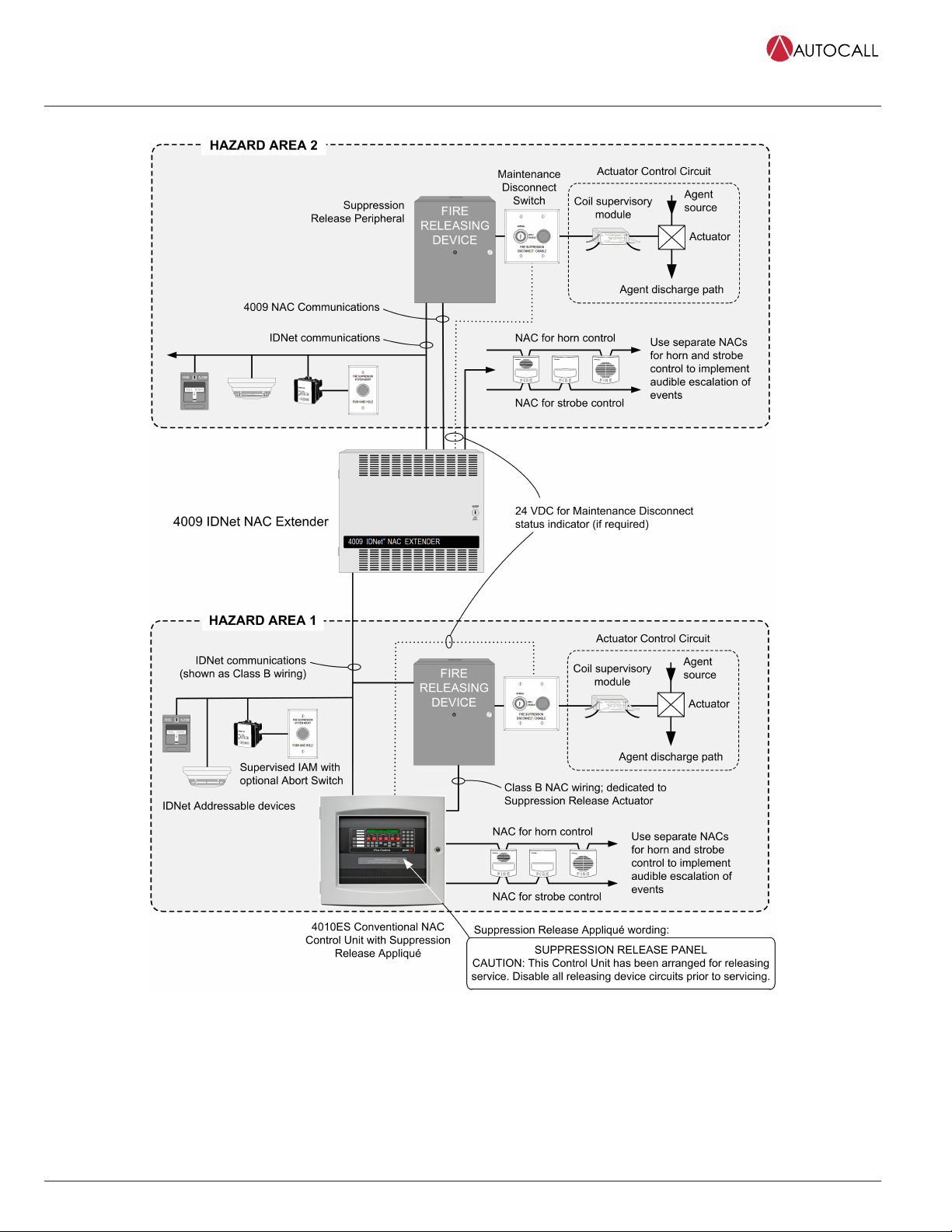
4010ES Fully Addressable Control Unit Releasing System One-Line Diagram
Figure 2: 4010ES Fully Addressable Control Unit Releasing System One-Line Diagram
Page 5 AC4010-0005 Rev. 10 5/2017
4010ES Automatic Extinguishing, Deluge and Preaction Sprinkler System Releasing Control
4010ES Conventional NAC Panel Releasing System One-Line Connection Reference
Figure 3: 4010ES Conventional NAC Panel Releasing System One-Line Connection Reference

Page 6 AC4010-0005 Rev. 10 5/2017
4010ES Automatic Extinguishing, Deluge and Preaction Sprinkler System Releasing Control
Suppression Release Peripheral Wiring Reference
Figure 4: Suppression Release Peripheral Wiring Reference
Note: Figure 4 shows:
• A2080-9059 / A2080-9060 maintenance disconnect switch with indicator lamp. A2080-9069 / A2080-9070 maintenance disconnect switch without
lamp not shown.
• A4090-9005 suppression release peripheral
• A2080-9056 / A2080-9057 abort switch
Page 7 AC4010-0005 Rev. 10 5/2017
4010ES Automatic Extinguishing, Deluge and Preaction Sprinkler System Releasing Control
Specifications
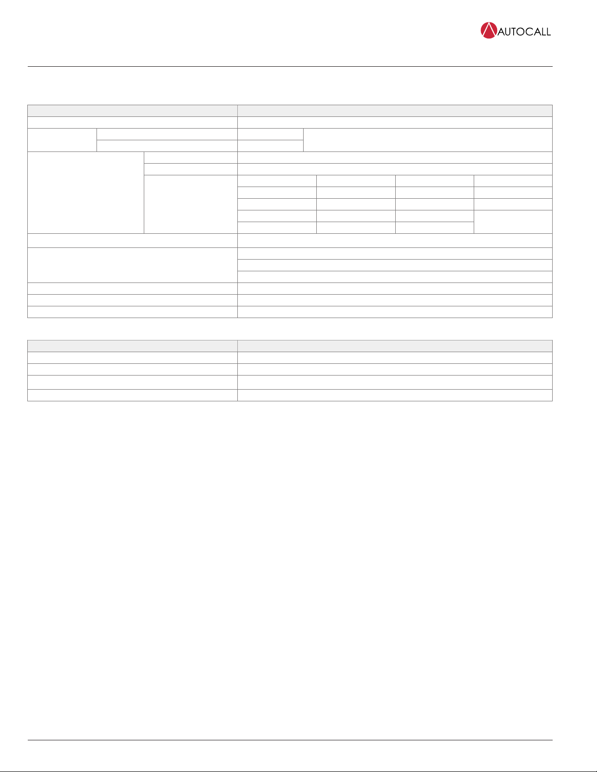
Table 5: Suppression Release Peripheral A4090-9005 and A4090-9006
Specification Rating
Communications IDNet, one address
with 4010ES 2 A maximum
RAC Output Rating with 4009 IDNet NAC Extender 1 A maximum
At nominal 24 VDC, regulated; refer to NAC Power Requirements for
more detail
Voltage 16 to 32 VDC (nominal 24 VDC)
Supervisory Current No additional current required, circuit appears as standard end-of-line (EOL) NAC loading
RAC Current NAC Current RAC Current NAC Current
0.5 A 0.845 A 1.25 A 2.14 A
0.75 A 1.28 A 1.5 A 2.56 A
0.87 A 1.5 A 1.75
NAC Power Requirements
Note:
4010ES NACs are rated at 3
A; 4009 IDNet NAC Extender
NACs are rated at 2 A, Extender
expansion NACs are rated 1.5 A
Alarm Current Reference
(RAC current = actuator
current)
1 A 1.71 A 2 A 3 A
Wire Connections Screw terminals for input and output wiring, 18 to 12 AWG wire (0.82 mm2 to 3.31 mm2)
Up to 2500 ft (762 m) from the IDNet source module
Up to 10,000 ft (3048 m) total Class B wiring distance including T-TapsIDNet Wiring Distance Reference
Compatible with Autocall A2081-9044 Overvoltage Protectors
Dimensions SeeSuppression Release Peripheral Installation Reference Diagram
Operating Temperature 32 °F to 120 °F (0 °C to 49 °C) indoor operation only
Operating Humidity Range 10 to 90% RH at 90 °F (32 °C)
Table 6: Coil Supervision Module A2081-9046
Specification Rating
Construction Epoxy encapsulated
Dimensions 1-3/8" W x 2-7/16" L x 1-1/16" H (34 mm x 62 mm x 27 mm)
Wiring 18 AWG (0.82 mm2) wire leads, color coded
Current Rating 2 A Maximum; internally fused at 3 A, non-replaceable
Page 8 AC4010-0005 Rev. 10 5/2017
4010ES Automatic Extinguishing, Deluge and Preaction Sprinkler System Releasing Control
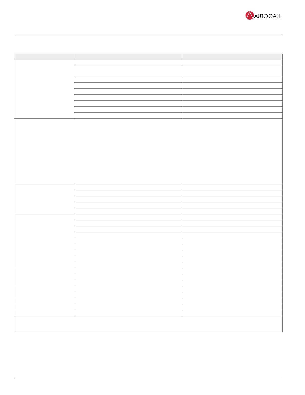
Compatible UL Listed Valves and Actuators
Table 7: Compatible UL Listed Valves and Actuators
Manufacturer Model Number Electrical Ratings
AUTOMAN II-C Assembly (solenoid 17728; coil 25924) 24VDC, 750 mA
AUTOMAN II-C Explosion-Proof Releasing Device (solenoid
31492; coil 31438) 24 VDC, 750 mA
AUTOMAN II-C Assembly (solenoid 68739; coil 25924) 24VDC, 750 mA
Solenoid Electric Actuator (solenoid 73111; coil 73097) 24 VDC, 1A
CV90 HF Electric Actuator 73327 *24 VDC, 570mA
LP CO2 w/ASCO solenoid 422934 24 VDC, 442 mA
LP CO2 double action 24 VDC solenoid 430948 24 VDC, 438 mA
LP CO2 3-way selector valve solenoid 433419 24 VDC, 438 mA
ANSUL
Electric Actuator 24 VDC solenoid 570537 24 VDC, 250 mA
LPG
Solenoid Electric Actuator (uses solenoid: Flow Control
609500/671S)
Solenoid Coupling Assembly 21006401 (uses solenoid: Flow
Control 609500/671S)
Solenoid Coupling Assembly 21006402 (uses solenoid: Flow
Control 609500/671S)
LPG128/145/190/230-50/55 FM-200 valves (uses solenoid:
Flow Control 609500/671S)
LPG128-90UL iFLOW and FM-200 valve (uses solenoid: Flow
Control 609500/671S)
24 VDC, 542 mA
71395SN2ENJ1NOH111C2 (Skinner coil H111C2) 24 VDC, 420 mA
73212BN4TN00NOC111C2 (Skinner coil C111C2) 24 VDC, 420 mA
73212BN4TNLVNOC322C2 (Skinner coil C322C2) 24 VDC, 830 mA
73218BN4UNLVNOH111C2 (Skinner coil H111C2) 24 VDC, 410 mA
Skinner
73218BN4UNLVNOC111C2 (Skinner coil C111C2) 24 VDC, 410 mA
8210A107 (097617-005D coil) 24 VDC, 750 mA
8210G207 (238310 coil) 24 VDC, 440 mA
8211A107 (097617-005D coil) 24 VDC, 750 mA
8262H182 (238910 coil) 24 VDC, 483 mA
HV2628571 (23810 coil) 24 VDC, 442 mA
HV2648581 (23810 coil) 24 VDC, 442 mA
EF8210G001MBMO (238714 coil) 24 VDC, 450 mA
R8210A107 (097617-005D coil) 24 VDC, 700 mA
ASCO
T8210A107 (097617-005D coil) 24 VDC, 700 mA
ECH Electrical Control Head (551201) 24 VDC, 1700 mA
Explosion-Proof Electric Actuator (570147) 24 VDC, 396 mAPyro-Chem
Removable Electric Actuator (570209) 24 VDC, 200 mA
304.205.010 – Electrical Actuator Suppression Diode 24 VDC, 250 mA
Hygood 304.209.001 – Electrical Actuator Bridge Rectifier 24 VDC, 250 mA
Minimax Model MX1230 without diode 24 VDC, 500 mA
Versa CGS-4292-NB3-S20000 24 VDC, 438 mA
Burkert 5282 2/2-Way Solenoid Valve 24 VDC, 333 mA
* For 24 VDC, 450 mA activation, requires a 73886 (21.5 ohm, 23 watt) in-line resistor shipping assembly ordered separately.
For additional information refer to the manufacturer’s technical documentation.
Page 9 AC4010-0005 Rev. 10 5/2017
4010ES Automatic Extinguishing, Deluge and Preaction Sprinkler System Releasing Control
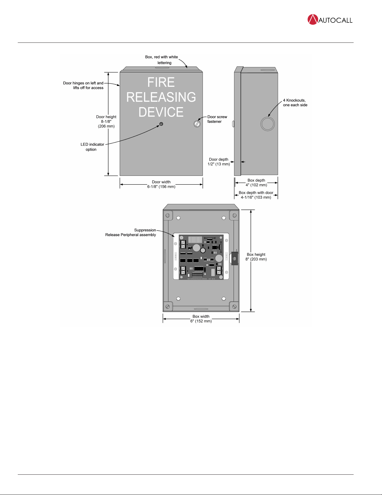
Suppression Release Peripheral Installation Reference Diagram
Figure 5: Suppression Release Peripheral Installation Reference Diagram
Note: Figure 5 shows:
• A2975-9227 Box, red with white lettering (supplied with A4090-9006)
• 4090-9812 LED indicator option (supplied with A4090-9006)
• A4090-9005 Suppression Release Peripheral assembly (supplied with A4090-9006)

AC4010-0005 Rev. 10 5/2017
© 2018 Johnson Controls. All rights reserved. All specifications and other information shown were current as of document revision and are subject to change without notice.
Additional listings may be applicable, contact your local Autocall product supplier for the latest status. Listings and approvals under Tyco Fire & Security GmbH, and the
product names listed in this material are marks and/or registered marks. Unauthorized use is strictly prohibited. NFPA 72 and National Fire Alarm Code are registered
trademarks of the National Fire Protection Association (NFPA).
Table of contents
Popular Control Unit manuals by other brands

Festo
Festo Compact Performance CP-FB6-E Brief description

Elo TouchSystems
Elo TouchSystems DMS-SA19P-EXTME Quick installation guide

JS Automation
JS Automation MPC3034A user manual

JAUDT
JAUDT SW GII 6406 Series Translation of the original operating instructions

Spektrum
Spektrum Air Module System manual

BOC Edwards
BOC Edwards Q Series instruction manual

KHADAS
KHADAS BT Magic quick start

Etherma
Etherma eNEXHO-IL Assembly and operating instructions

PMFoundations
PMFoundations Attenuverter Assembly guide

GEA
GEA VARIVENT Operating instruction

Walther Systemtechnik
Walther Systemtechnik VMS-05 Assembly instructions

Altronix
Altronix LINQ8PD Installation and programming manual


