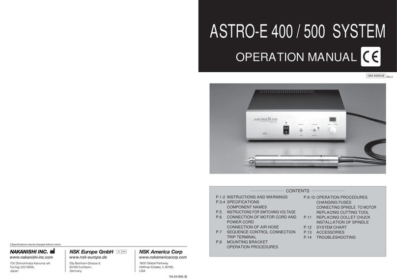
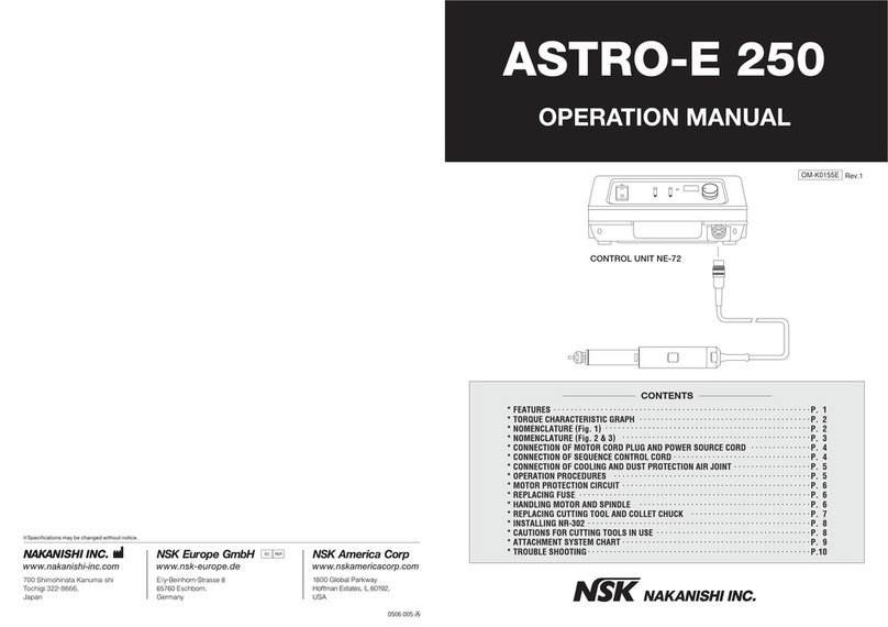
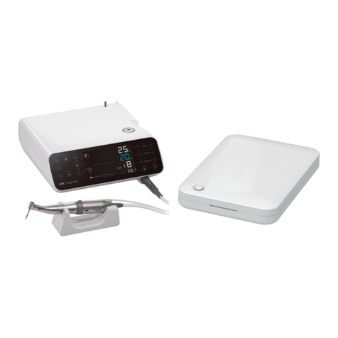
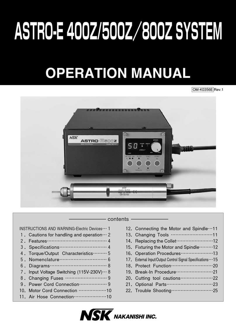
NSK Ultimate XL-F User manual


OPERATION MANUAL
Micromotor for Laboratory Work
English


1
Thank you very much for purchasing ULTIMATE XL-F.
Please read this Operation Manual carefully regarding the instructions for use, handling method,
and maintenance and inspection prior to use and store it in a place where users can review it
anytime.
IMPORTANT INSTRUCTIONS AND WARNING - Electric Devices
1. Component Names
2. Set up of Control Unit
3. Operation Procedure
4. Operation Procedure of Air Turbine (Option)
5. Protective Circuit for Motor
6. Memory Function
7. When Abnormal Conditions Occur
8. Replacement of Fuse
9. Vacuum-coupled Mode
10. Handling of Motor and Handpiece
11. Specification
12. Troubleshooting
13. Disposing Product
2
5
6
7
7
7
8
8
8
8
9
11
11
12
···················
··················································································
···············································································
················································································
··············································
·······································································
······················································································
····························································
···············································································
············································································
···························································
·····························································································
························································································
····················································································
Contents
English

2
A. GROUNDING INSTRUCTIONS
Grounding Method
1. In the event of a malfunction or breakdown, grounding provides a path of least resistance for
electric current to reduce the risk of electric shock. This tool is equipped with an electric cord
having an equipment-grounding conductor and a grounding plug. The plug must be plugged
into a matching outlet that is properly installed and grounded in accordance with all local
codes and ordinances.
2. Do not modify the plug provided - if it will not fit the outlet, have the proper outlet installed by
a qualified electrician.
3. Improper connection of the equipment-grounding conductor can result in a risk of electric
shock. The conductor with insulation having an outer surface that is green with or without
yellow stripes is the equipment-grounding conductor. If repair or replacement of the electric
cord or plug is necessary, do not connect the equipment grounding conductor to a live
terminal.
4. Check with a qualified electrician or service personnel if the grounding instructions are not
completely.
Understood, or if in doubt as to whether the tool is properly grounded.
5. Use only 3-wire extension cords that have 3-prong grounding plugs and 3-pole receptacles
WKDWDFFHSWWKHWRROVSOXJ
6. This tool is intended for use on a circuit that has an outlet that looks like the one illustrated in
6NHWFK$LQ)LJXUHEHORZ97KHWRROKDVDJURXQGLQJSOXJWKDWORRNVOLNHWKHSOXJ
LOOXVWUDWHGLQ6NHWFK$LQ)LJXUHEHORZ$WHPSRUDU\DGDSWHUZKLFKORRNVOLNHWKHDGDSWHU
illustrated in Sketches B and C, may be used to connect this plug to a 2-pole receptacle as
shown in Sketch B if a properly grounded outlet is not available. The temporary adapter
should be used only until a properly grounded outlet can be installed by a qualified
electrician. The green-colored rigid ear, lug, and the like, extending from the adapter must be
connected to a permanent ground such as a properly grounded outlet box.
Grounding plug
pin
Metal screw
Grounding means
Grounding pin
ADAPTER
Cover of ground outlet box
When using electric tools, basic safety precautions should always be followed to reduce
the risk of fire, electrical shock and personal injury, including the following. Read all these
instructions before operating this product and save these instructions.
WARNING
IMPORTANT INSTRUCTIONS AND WARNING-Electric Devices

3
7. USE PROPER EXTENSION CORD. Make sure your extension cord is in good condition.
When using an extension cord, be sure to use one heavy enough to carry the current your
product will draw. An undersized cord will cause a drop in line voltage resulting in loss of
power and overheating. Table (below) shows the correct size to use depending on cord
length and nameplate ampere rating. If in doubt, use the next heavier gauge. The smaller the
gauge number, the heavier the cord.
8. Install equipment so that the power supply cord can be pulled out without hindrance in event
of emergency. Do not place anything within 10 centimeters around the unit.
Ř)RU\RXURZQVDIHW\UHDGLQVWUXFWLRQPDQXDOEHIRUHRSHUDWLQJWRRO
Ř:HDUH\HSURWHFWLRQ
Ř5HSODFHFUDFNHGZKHHOLPPHGLDWHO\
Ř$OZD\VXVHJXDUGVDQGH\HVKLHOGV
Ř'RQRWRYHUWLJKWHQZKHHOQXW
Ř8VHRQO\ƃDQJHVIXUQLVKHGZLWKWKHJULQGHU
Ř5(029($'-867,1*.(<6$1':5(1&+(6)URPKDELWRIFKHFNLQJWRVHHWKDWNH\V
and adjusting wrenches are removed from tool before turning it on.
Ř.((3:25.$5($&/($1&OXWWHUHGDUHDVDQGEHQFKHVLQYLWHDFFLGHQWV
Ř'21786(,1'$1*(5286(19,5210(17'RQWXVHSRZHUWRROVLQGDPSRUZHW
ORFDWLRQVRUH[SRVHWKHPWRUDLQ.HHSZRUNDUHDZHOOOLJKWHG
Ř5LVNRILQMXU\GXHDFFLGHQWDOVWDUWLQJ'RQRWXVHLQDQDUHDZKHUHFKLOGUHQPD\EH
present.
Ř'217)25&(722/,WZLOOGRWKHMREEHWWHUDQGVDIHUDWWKHUDWHIRUZKLFKLWZDV
designed.
Ř86(5,*+7722/'RQWIRUFHWRRORUDWWDFKPHQWWRGRDMREIRUZKLFKLWZDVQRW
designed.
Ř:($53523(5$33$5(/'RQRWZHDUORRVHFORWKLQJJORYHVQHFNWLHVULQJV
bracelets, or other jewelry that might get caught in moving parts. Nonslip footwear is
recommended. Wear protective hair covering to contain long hair.
Ř$/:$<686(6$)(7<*/$66(6(YHU\GD\H\HJODVVHVRQO\KDYHLPSDFWUHVLVWDQW
lenses, they are NOT safety glasses. Also use face or dust mask if cutting operation is
dusty.
B. OTHER WARNING INSTRUCTIONS
Minimum gauge for cord
9ROWV
9
9
7RWDO/HQJWKRIFRUG
Cord Number
Ampere Rating
More Than
0
6
10
12
Not More Than
6
10
12
16
7.5m(25ft.)
15m(50ft.)
#18
#18
#16
#14
15m(50ft.)
30m(100ft.)
#16
#16
#16
#12
30m(100ft.)
60m(200ft.)
#16
#14
#14
45m(150ft.)
90m(300ft.)
#14
#12
#12
Not Recommended
English

C. Important Instructions and Warning on ULTIMATE XL-F.
Ř6(&85(:25.8VHFODPSVRUDYLVHWRKROGZRUNZKHQSUDFWLFDO,WVVDIHUWKDQXVLQJ
\RXUKDQGDQGLWIUHHVERWKKDQGVWRRSHUDWHWRRO
Ř0$,17$,1722/6:,7+&$5(.HHSWRROVVKDUSDQGFOHDQIRUEHVWSHUIRUPDQFHDQGWR
UHGXFHWKHULVNRILQMXU\WRSHUVRQV)ROORZLQVWUXFWLRQVIRUOXEULFDWLQJDQGFKDQJLQJ
DFFHVVRULHV
Ř',6&211(&7722/6EHIRUHVHUYLFLQJZKHQFKDQJLQJDFFHVVRULHVVXFKDVEODGHV
ELWVFXWWHUVDQGOLNH
Ř5('8&(7+(5,6.2)81,17(17,21$/67$57,1*0DNHVXUHVZLWFKLVLQRIISRVLWLRQ
EHIRUHSOXJJLQJLQ
Ř86(5(&200(1'('$&&(6625,(6&RQVXOWWKHRZQHUVPDQXDOIRUUHFRPPHQGHG
DFFHVVRULHV7KHXVHRILPSURSHUDFFHVVRULHVPD\FDXVHULVNRILQMXU\WRSHUVRQV
Ř1(9(5/($9(722/5811,1*81$77(1'('785132:(52))'RQWOHDYHWRRO
XQWLOLWFRPHVWRDFRPSOHWHVWRS
Ř)RUUHFRPPHQGHGRSHUDWLQJVSHHGIRUYDULRXVDSSOLFDWLRQVSOHDVHIROORZWKHLQVWUXFWLRQV
RIEXUPDQXIDFWXUHUV
Ř7KHV\VWHPIXQFWLRQVQRUPDOO\LQWKHHQYLURQPHQWZKHUHWKHWHPSHUDWXUHLVDWr&
KXPLGLW\DW5+DQGQRPRLVWXUHFRQGHQVDWLRQLQWKH8QLW8VHDWRXWVLGHRI
WKHVHOLPLWVPD\FDXVHPDOIXQFWLRQ
Ř6WRUHWKHV\VWHPLQWKHSODFHZKHUHWKHWHPSHUDWXUHLVDWr&KXPLGLW\DW
5+DWPRVSKHULFSUHVVXUHDWK3DDQGWKHV\VWHPLVQRWVXEMHFWWRDLUZLWK
GXVWVXOIXURUVDOLQLW\
Ř6HYHUHVKRFNŎ(J'URSSLQJ&RQWURO8QLWRUWKH0LFURPRWRŎPD\FDXVHGDPDJH
Ř1HYHUPRYH&KXFN&RQWURO5LQJWRWKHGLUHFWLRQRI/226(1ZKLOHPRWRULVUXQQLQJ
Ř$FWLYDWLRQRI&LUFXLW%UHDNHUPHDQVWRRPXFKORDGLVDSSOLHGWRWKHPRWRUEH\RQGWKH
FDSDFLW\WKHPRWRUWDNHV7KLVFLUFXLWEUHDNHULVGHVLJQHGWRSURWHFWWKHPRWRUEXWLWLV
GHVLUHGWRSHUIRUPWKHJULQGLQJZRUNZLWKRXWDFWLYDWLQJWKHFLUFXLWEUHDNHU
Ř&DUHVKRXOGEHWDNHQQRWWRGURSPLFURPRWRUKDQGSLHFHRQƃRRURUKDUGZRUNVXUIDFHLQ
RUGHUWRDYRLGGDPDJHFDXVHGE\LPSDFWVKRFN
Ř'RQRWGLVDVVHPEOHRUDOWHUWKHSURGXFWE\\RXUVHOI
Ř%HFDUHIXOQRWWREHLQMXUHGE\WKHJULQGHURUEXU
Ř%HVXUHWRUHSODFHIXVHZLWKWKHFRUUHFWW\SHDQGUDWLQJ
Ř
1ROXEULFDWLRQLVUHTXLUHGWRHLWKHUPRWRURUKDQGSLHFHEHFDXVHEDOOEHDULQJVLPSUHJQDWHG
ZLWKJUHDVHLQERWKPRWRUDQGKDQGSLHFH
Ř2QO\XVHZLWKRULJLQDOSRZHUVXSSO\FRUG,QFDVHRIGDPDJHFRQWDFW16.1DNDQLVKL
VHUYLFLQJFHQWHU
Ř(TXLSPHQWWREHVHQGEDFNWRPDQXIDFWXUHUIRUVHUYLFLQJUHSDLU

1. Component Names
&RQWURO8QLW
0RWRU+DQGSLHFH
7XUELQH$GDSWHURSWLRQ
$LU7XUELQHRSWLRQ
0DLQ6ZLWFK
7XUELQH0RWRU6HOHFWRU6ZLWFK
3RZHU,QGLFDWRU
)RUZDUG5HYHUVH6HOHFWRU6ZLWFK
6SHHG&RQWURO3HGDO
0D[LPXP(QJLQH6SHHG6HWWLQJ6ZLWFK
$XWR&UXLVH6ZLWFK
7XUELQH$GDSWHU&RQQHFWRU
0RWRU&RQQHFWRU
)XVH%R[
+DQGSLHFH6WDQG
English

6
2. Set up of Control Unit
(1) Mounting of Motor
Insert the motor cord plug locator into
Motor
Connector aligning it with the groove of the
connector, and tighten the motor cord plug nut
to fix. (Fig. 1)
(2) Connecting of Power Cord
Securely insert the plug of Power Cord in to
Connector Box at the back of the unit aligning it
with the configuration. (Fig. 2)
(3) Mounting of the Air Turbine
(option)
Insert the plug of the Turbine Adapter into the
Turbine Adapter Connector at the back of the
unit. (Fig. 3)
Insert two hoses from the Turbine Adapter
into the openings for foot pedal connection in
the air line kit. (Fig. 4)
13
3
3
Fig. 1
Fig. 2
Fig. 3
Fig. 4
12
Foot Pedal
Connector
IN
IN
AIR IN
To XL-F
OUT
OUT
Foot Pedal Connector

English
7
Connect the power cord to connector.
Preset the maximum rotation speed with the Maximum Engine Speed Setting Switch
(ON : 40,000min-1 (rpm), OFF : 30,000 min-1(rpm).
Select Auto cruise or Variable by the Auto Cruise Switch.
Turn the Main Switch on, and the Power Indicator lamps.
Push the Speed Control Pedal right to run the motor. The rotation speed can be variably
controlled within the preset maximum rotation speed range according to the degree of
depression of the Speed Control Pedal.
Each time Forward/Reverse Selector Switch is depressed, the direction changes between
FORWARD and REVERSE
Auto cruise mechanism
To run the motor at a fixed speed without pushing the Speed Control Pedal, push the
Auto Cruise Switch to “Auto” and keep on pushing the Speed Control Pedal for
a second at a proper speed. Push the pedal again to cancel it, (if it is unnecessary, turn the
Auto Cruise Switch off).
When the motor is operated with a load exceeding the limit or the handpiece is in an
unrotatable condition, the circuit to protect the motor and unit operates to stop the power
supply to the motor, whereby the Power Indicator goes on and off.
How to reset the protective circuit
It can be reset by depressing the Speed Control Pedal again after eliminating the cause of
the error.
Each time the Motor/Turbine Selector Switch is pressed, the motor and turbine change by
turns.
In case of no turbine, nothing changes except beeps.
• When Auto cruise mechanism is OFF:
Push the Speed Control Pedal, and the turbine rotates. Stop pushing the pedal, and
the turbine stops.
• When Auto cruise mechanism is ON:
Push the Speed Control Pedal for a second, and the turbine continues to move even if
the pedal is not pushed. Push the pedal again to cancel it.
Even if Forward/Reverse Selector Switch is pushed while using the air turbine, it will be
neglected only with the beeps of electronic sounds.
Push the Motor/Turbine Selector Switch again, and the motor will be available.
11
9
9
9
9
9
9
11
11
6
8
8
5
5
3. Operation Procedure
4. Operation Procedure of Air Turbine (Option)
5. Protective Circuit for Motor
1
2
3
4
1
2
3 6
7
7

8
6. Memory Function
When the main switch is turned on, the rotation direction and the Motor/Turbine selections
made when the main switch was last turned off are restored. Special attention should be given
to the rotation direction.
7. When Abnormal Conditions Occur
When problems connected with the motor or unit occurs, the power supply to the motor will
stop and the power indicator flashes. Unlike being stopped by the protection circuit, the motor
will not start even when the pedal is depressed. If such a problem occurs, please ask for repair
service.
On some dental tables with vacuum dust collector, the motor may be used while being coupled
with a dust collector. When such a dust collector * is used, power consumption of ULTIMATE
XL-F can be regulated so that the vacuum-coupled function can work. If you need coupling
with a vacuum dust collector, select the mode as follows:
How to select the mode
While pressing Forward / Reverse Selector Switch, turn on Main Switch, and the mode
can be selected. A long beep indicates vacuum-coupled mode and 2 short beeps indicate
non-coupled (energy-saving) mode.
* Each time the switch selection is made, the mode changes between vacuum-coupled mode
and non-coupled mode.
* A currently known dust collector is KAVO EWL-560.
8. Replacement of Fuse
9. Vacuum-coupled Mode
Fuse is located in Fuse Box . Release ratchet
clamp located on the right-and-left the Fuse Box
and pull it out to change the fuse. (Fig.5)
When the fuse come down, Insert new fuses into the fuse box and then push the fuse box into
the original position until hearing a sound click.
Fuse: Order Code (120V) : 1202225010 (T2.5AH 250V)
Fuse: Order Code (230V) : 1202216010 (T1.6AH 250V)
7
14
8 5
Fig.5
Fuse is burned out when a short circuit occurs or when over-voltage is flowed into the
primary current source. If the cause is uncertain, return the product to an authorized
NSK's service shop for inspection.
CAUTION

English
If a bur having a large diameter of a cutting
part is used under a high torque, the chuck
may rotate in the close direction and the bur
may be stuck and cannot be removed. In this
case, align the nose's slit and spindle's
spanner position (flat part), and apply an L
spanner to fix the spindle. Open the ring and
turn the chuck counterclockwise with the
provided spanner wrench to remove it. (Fig.8)
9
(1) Insertion or Removal of Bur
The chuck is opened by turning the Bur Lock
Ring to an open position. The chuck is loosened
and the bur can be removed. By turning the ring
in the LOCK direction, the chuck is closed and
the bur can be mounted. At this time, turn the
ring until it clicks. (Fig. 6)
(2) Cleaning and Replacement of Chuck
(1) Removal of Chuck
To remove the chuck, open the ring and turn
the chuck counterclockwise with the provided
spanner wrench. (Fig. 7)
(2) Cleaning of Chuck
To keep accuracy for the Chuck remove and clean the chuck as frequently as possible in the
ultrasonic cleaner. Clean at least once a week.
10. Handling of Motor and Handpiece
Ř'RQRWWXUQWKH5LQJGXULQJURWDWLRQ
Ř'RQRWWXUQDPRWRUZKHQLWKDVQRWDWWDFKHGEXURUWKH5LQJ2SHQSRVLWLRQ,WPD\EH
reasons for the failure or overheating of the handpiece.
CAUTION
Neglecting to clean the chuck for a long time is very dangerous because wax,
gypsum,etc., accumulate in the chuck and the bur is caught insecurely, causing runout.
CAUTION
Fig. 6
LOCK
OPEN
Fig. 7
LOOSELOOSELOOSELOOSE
Fig. 8
LOOSELOOSE

10
(3) Disconnecting and Connecting of Motor Cord to Motor
Remove the cord nut at the rear end of the motor, and the motor cord connector can be pulled
out. For connection, align the connector pin and the hole in the motor cord connector, and
insert the connector straight until it stops. Then, tighten the cord nut.(Fig.10)
When inserting the connector, do not turn or twist it.
(3) Insertion of Chuck
Thinly apply oil before insertion. Open the
ring, insert the dummy bur or the bur in use
into the chuck, and turn the chuck clockwise
by hand until it stops. Then, lock the ring,
and the chuck could hold the bur securely.
(Fig. 9)
When connecting the handpiece to the
motor, turn the handpiece clockwise and
tighten firmly. If the clutch is not engaged
properly, the handpiece cannot be
tightened completely. In such case, Do
Not Force. Loosen the handpiece and
turn the bur briefly to re-position the drive dog. Reconnect the handpiece and tighten
securely. (Fig. 12)
CAUTION for Handpiece connection
Before using the handpiece, make sure to pull the rotating instrument (bur, etc.) to check
that it is securely mounted.
CAUTION
Fig. 9
Turn until finger-tightTurn until finger-tight
Fig. 10
(4) Disconnecting Handpiece from Motor
The handpiece and motor are screwed at the
midpoint. Firmly grasp the motor outer case and
the handpiece outer case and turn it
counterclockwise to disconnect. (Fig. 11).
Fig. 11
Fig. 12
Torque Type/ Compact Type

English
11
Please check the following points before sending back instruments for repair.
(Unit / Motor)
11. Specification
12. Troubleshooting
Motor Handpiece
1) Torque Type
Model
Speed
Max. Torque
Weight
Dimensions
Cord Length
UMXL-T(P) / UMXL-T(P)2M
1,000~40,000 min-1
8.7 N · cm
215g (exclude the cord)
L151x 29mm
2.0m
Model
Weight
Handpiece Stand
120g
Control Unit
Model
Power supply
Rated Power
Weight
Dimensions
NE230
AC120V 50/60 Hz 46VA
AC230V 50/60 Hz 46VA
46VA
3.8kg
W230x D292x H113mm
2) Compact Type
Model
Speed
Max. Torque
Weight
Dimensions
Cord Length
UMXL-C 2M
1,000~40,000 min-1
6 N · cm
181g (exclude the cord)
L144 x 27mm
2.0m
Trouble Cause/Check Remedy
The Power Indicator
does not light up.
The power
indicator flashes
when the pedal
is depressed.
Check that the power plug is
connected.
Check that the fuse has not burnt
out.
Check the power switch for
malfunction.
The power indicator soon starts
flashing even though the pedal is
depressed.
The motor handpiece sometimes
starts turning if the pedal is
depressed several times.
The motor handpiece starts
turning immediately when the
pedal is depressed.
Insert the power plug correctly.
Replace it with a specified fuse. If the
reason the fuse has blown is unknown,
ask for an inspection.
Ask for repair.
If the signal from the motor is not
transmitted to the unit, a problem will
occur. Check the motor cord again to
determine if it is damaged and is
connected correctly. If the motor cord
is damaged or the cause is not
determined, please ask for repair
service.
The trouble could be from the brake
circuit. Please ask for repair service.
The problem could be due to the
excess current in the detection of the
circuit. Stop operating the motor for a
while.
The motor and handpiece do not run.
The power indicator flashes.
Handpiece Stand

12
( Unit / Motor )
Trouble Cause/Check Remedy
The power
indicator flashed
in
5
to
6
seconds
after depressing
the pedal.
The motor
handpiece
comes to a stop
under a heavy
load.
The power
indicator remains
flashing even
when the power
is switched on
again.
Check that the chuck ON/OFF
ring is not open.
Try to turn the bur with your
finger.
It returns to normal immediately if
tried again.
The unit is hot to touch.
The unit is not hot to touch.
Set the chuck ON/OFF ring to the
LOCK position.
If the bur does not turn, it will affect the
motor or handpiece. Please ask for
repair service.
The protection circuit is started. The
motor must not be used to activate the
protection circuit.
Start the unit again after stopping
operation and letting it cool for 10
minutes. Check the operation of the
unit, and if it operates normally, there is
no problem.
There is a malfunction in the internal
memory. Please ask for repair service.
The motor and handpiece do not run.
The power indicator flashes.
( Handpiece )
Trouble Cause/Check Remedy
The handpiece does
not run with the
chuck tightened.
Heat is generated
during rotation.
Vibration or noise
occurs during
rotation.
Runout of the bur is
heavy.
The bur comes out
Entry of foreign matter in the ball
bearings or seizure.
Entry of foreign matter in the ball
bearings, causing wear of the
bearings.
Same as the above.
A bent bur is used.
Dust may be stuck in the chuck
or spindle.
The chuck is worn.
The ball bearings are worn.
The chuck is loose.
Send it to your dealer. Ask for repair.
Same as the above.
Same as the above.
Replace the bur.
Clean the inside of the chuck and
spindle.
Replace the chuck.
Send it to your dealer.
Tighten the chuck securely. (See
10. Handling of Motor and Handpiece.)
Please consult with dealer from whom you purchased it about waste disposal.
13. Disposing Product

BEDIENUNGSANLEITUNG
Labor-Mikromotor
Deutsch


15
Vielen Dank, dass Sie sich fur den Kauf des ULTIMATE XL-F entschieden haben. Bitte lesen Sie
die Anweisungen zur Bedienung, Pflege und Wartung in diesem Handbuch vor der
Inbetriebnahme sorgfaltig durch. Bewahren Sie dieses Bedienungshandbuch fur spatere
Verwendung auf.
WICHTIGE ANWEISUNGEN UND WARNUNG – Elektronische Geräte
1. Namen der Komponenten
2. Einrichten der Steuereinheit
3. Betriebsverfahren
4. Betriebsverfahren der Luftturbine (Option)
5. Schutzschaltkreis
6. Memory-Funktion
7. Wenn abnormale Bedingungen auftreten
8. Auswechseln der Sicherung
9. Kupplung an Absaugung
10. Handhabung von Motor und Handstück
11. Technische Daten
12. Fehlerbehebung
13. Entsorgung des Produktes
16
19
20
21
21
21
22
22
22
22
23
25
26
27
···············
········································································
······································································
······················································································
················································
·····················································································
·····················································································
··················································
·····································································
··········································································
··················································
·····················································································
·······················································································
······································································
Inhalt
Deutsch

16
A. ERDUNGSANWEISUNGEN
1. Im Falle einer Fehlfunktion oder eines Ausfalls bietet die Erdung einen Weg des geringsten
Widerstands für den elektrischen Strom, um die Gefahr eines Stromschlags zu reduzieren.
Dieses Gerät ist mit einem Stromkabel ausgestattet, das einen Erdungsleiter und einen
geerdeten Stecker besitzt. Der Stecker muss in eine passende Steckdose gesteckt werden,
die korrekt installiert und entsprechend aller geltenden Vorschriften geerdet ist.
2. Den mitgelieferten Stecker nicht verändern – wenn er nicht in die Steckdose passt, lassen Sie
die richtige Steckdose von einem qualifizierten Elektriker installieren.
3. Unsachgemäßer Anschluss des Erdungsleiters kann zur Gefahr eines Stromschlags führen.
Der Leiter mit einer grünen oder grün-gelb gestreiften Isolierung ist der Erdungsleiter. Wenn
eine Reparatur oder ein Austausch von Stromkabel oder Stecker erforderlich ist, den
Erdungsleiter nicht an einen stromführenden Pol anschließen.
4. Überprüfen Sie die korrekte Erdung des Geräts zusammen mit einem qualifizierten Techniker
oder Kundendienstmonteur, wenn Sie die Erdungsanweisungen nicht vollständig verstanden
haben oder im Zweifel darüber sind.
5. Nur dreiadrige Verlängerungskabel verwenden, die dreizinkige Erdungsstecker und die
richtigen Buchsen für den Stecker des Geräts haben.
6. Dieses Gerät ist zur Verwendung an einem Stromkreis vorgesehen, der eine Steckdose wie in
Zeichnung A (unten) besitzt (120 V). Das Gerät besitzt einen Stecker wie in Zeichnung A
(unten). Ein provisorischer Adapter, wie unten in den Zeichnungen B und C dargestellt, kann
verwendet werden, um diesen Stecker mit einer zweipoligen Dose zu verbinden, wie in
Zeichnung B zu sehen, wenn keine korrekt geerdete Steckdose zur Verfügung steht. Der
provisorische Adapter sollte nur so lange verwendet werden, bis eine korrekt geerdete
Steckdose von einem qualifizierten Elektriker installiert werden kann. Das grüne, starre Öhr,
der Zapfen und andere Vorsprünge des Adapters müssen an eine permanente Erdung wie
beispielsweise eine korrekt geerdete Steckdose angeschlossen werden.
Bei der Verwendung elektrischer Geräte sollten stets einige grundsätzliche
Vorsichtsmaßnahmen befolgt werden, um die Gefahr von Feuer, Stromschlag und eigenen
Verletzungen zu reduzieren. Dazu gehören die nachfolgenden Maßnahmen. Lesen Sie alle
diese Anweisungen vor dem Betrieb dieses Produkts durch und bewahren Sie sie auf.
WARNUNG
WICHTIGE ANWEISUNGEN UND WARNUNG – Elektronische Geräte
Erdungsmethode
ERDUNGSPIN
METALL-
SCHRAUBE ERDUNGSMITTEL
ERDUNGSPIN
ADAPTER
ABDECKUNG DER
GEERDETEN STECKDOSE
Table of contents
Languages:
Other NSK Control Unit manuals
Popular Control Unit manuals by other brands

Amperes
Amperes PR7400 instruction manual

Teal Products
Teal Products CCU3 Installation & user manual

SCP SCIENCE
SCP SCIENCE DigiPREP Service manual

Telit Wireless Solutions
Telit Wireless Solutions LN940A11 SERIES user guide

vistaCNC
vistaCNC iMachIII P1B manual

Sensaphone
Sensaphone WEB600 quick start guide