manuals.online logo
Brands
  1. Home
  2. •
  3. Brands
  4. •
  5. ADTRAN
  6. •
  7. Control Unit
  8. •
  9. ADTRAN Total Access 300 Series Product manual

ADTRAN Total Access 300 Series Product manual

jobAid
1
DESCRIPTION
The Total Access® 300 Series Small Business Unit (SBU) Active Ethernet
Optical Network Terminals (ONT) are Gigabit Passive Optical Network
ONTs. This Job Aid describes the Installation of the Total Access 372E
Active Ethernet Small Business Unit ONT (P/N 1287723G1).
The ONTs support the following:
Eight POTS ports
Four DS1 circuit emulated T1 interfaces (for PBX application)
Two Gigabit Ethernet interfaces
Active Ethernet interface
The figure above illustrates the ONT inner enclosure for the Total Access
372E.
NOTE
The Electronics Module Safety Cover and Fiber Tray Cover have been
removed to show additional details.
Optical technology provides a consistent and common approach to
advancing the public communications network using:
Plain Old Telephone Service (POTS)
High speed data and video services
PBX services
ACTIVE ETHERNET
Active Ethernet uses Ethernet components that are 802.3ah
compliant. Active Ethernet provides dedicated bandwidth based on
individual subscriber requirements that are applicable to both
Note: Safety Cover has been
removed for illustration purposes.
Fiber In
Ground
Power
Note: Cable color is for
clarity purposes only.
Note:
When using the NID Housing,
ground the unit using the Ground
Lug attached to the Mounting Plate.
TELEPHONETROUBLESHOOTING:
1.Identify the bad line (POTS 1-8).
2.Plug any working phone into
theappropriatejack.
If the telephone works, the unit
isfunctioningnormally.
If the telephone does not work,
contactyourservice provider.
3.Remove the telephone from the
POTSjack.
TOTALACCESS372E
1287723G1
LOWBAT
BATMIS
REP BAT
ON BAT
SIG RTN
12VRTN
+12VDC
Note: The RJ-11 POTS
ports are used for test
purposes only.
Tip (Green)
Ring (Red)
Fiber Jumper
Cable (Yellow)
Ethernet
Connection (White)
DS1
Connection (Red)
Active Ethernet
Connecton
Strength
Member
(Red)
Cable
Support
Clamp
Fiber
Splice Tray
Total Access 300 Series
Active Ethernet
Small Business Unit
residential and business applications. Because Active Ethernet is pure
IP, no transition protocol is required.
The ONT and OLT employ bi-directional Small Form-factor
Pluggable (SFP) connectors for data transmission. To allow for trans-
mission of downstream and upstream traffic on a single fiber,
different wavelengths are used for each direction. Downstream traffic
uses 1490 nm, while Upstream traffic uses 1310 nm.
Using SFPs that are swappable depending on the application, using SFP-
based optics that are specific to the transmit and receive requirement (10
to 80 kilometers). Refer to the Total Access 300 Series Active Ethernet Small
Business Unit ONT Installation and Maintenance Guide
(P/N 612877SBAONT-5).
This Job Aid covers the electronics module and housings listed in the
following table:
NOTE
The Total Access 372 SBU ONT is only intended to be used with the
Corning Systems Model FNI-NG series outdoor NID housing listed
above.
FRONT PANEL LEDS
INSTALLATION
NOTE
Refer to the Total Access 300 Series SBU ONT Installation and Maintenance
Guide (P/N 612877SBGONT-5) for complete information on installing
these units both with, and without the NID Housing.
Total Access 300 Description
1287723G1 Total Access 372E SBU Active Ethernet Electronics Module
1187774G1 Standard Business Unit Model 774 Housing
1187775G1 Standard Business Unit Model 775 OptiTap Housing
Label Status Description
PWR 

Off
Green
No power
Power is On
NET 


Green
Yellow
Red
OLT has activated the ONT
OLT is discovering and ranging the
ONT
The OLT has shut down ONT
VOICE
1 – 8


2
Off
Green
Green Flashing
Fiber is disconnected, or GPON
interface is down
At least one port is Off Hook
At least one port is Ringing
DS1
1 – 4




Off
Green
Yellow
Alarm
Fiber is disconnected, or GPON
interface is down
Link is up
Link in test mode
Fault
ETHERNET
1 – 2


4
Off
Green
Yellow Flashing
Link is down, no activity, or Admin-
istratively Shut Down
10/100/1000 Link is up
TX or RX activity
Issue Date: July 2012
Document P/N: 612877SBAONT-22A
2612877SBAONT-22A
1. Align the slots on the reverse of the Electronics Module with the
tabs on the Enclosure.
2. Slide the Electronics Module on to the tabs and align the Screw Slot
with the threaded hole in the back plate.
3. Secure the Electronics Module using the #6 (P/N 3276003003-E)
screw provided.
Ground Connection
CAUTION
!
Do not use a knife to cut the opening in the rubber grommets. This may
result in an excessively large hole and compromise the integrity of the
unit allowing moisture into the unit.
Refer to the illustration on the first page, the illustration below, and the
following steps to connect the ground wire:
1. Remove the rubber grommet from the housing (Step 1).
2. Route a #6 ground wire through the rubber grommet (Step 2).
3. Trim the insulation back 1/2” on the ground wire and attach the
appropriate ground lug.
4. Route the ground wire as shown and attach it to the ground lug on
the back plate attached to the NID.
5. Replace the rubber grommet in the housing.
6. Route the ground wire 12 inches below finished grade by the
shortest and most direct route to the AC power ground system
Multi Grounded Neutral (MGN) of the customer premises. Ensure
the wire is free of any sharp bends.
7. Attach the ground wire to the subscriber premise with stainless
steel half moon clamps or tie-wrap the ground wire to the riser
conduit of the Buried Fiber Drop.
8. Clean the MGN connector with emery cloth to insure a stable
connection.
9. Attach the ground wire from the ONT to the MGN connector with
the appropriate UL approved ground clamp/fitting.
10. Coat the connection with a metal corrosion preventative.
11. Attach a Warning Ground Tag to this grounding connection.
Power/Alarm Connections
NOTE
Wiring the Power/Alarm connector improperly could damage the SBU.
The ONT is supplied with a 7-pin Power/Alarm connector. To make
connections from the Uninterruptible Power Supply (UPS) to the Power/
Alarm connector, refer to the illustration on the first page, the illustration
below, and Power/Alarm Connector Pin-Outs table on the following page
and complete the following steps:
1. Remove the Power/Alarm Connector by pulling it out of the Elec-
tronics Module.
123
Use this example for all grommet and ber/cable installations.
Pin 1
Pin 7
1
2
3
4
5
6
7
UPS Power
Connector
Power/Alarm
Connector
Low Battery
Battery Missing
Replace Battery
On Battery
Signal Return
12V Return
+12VDC
After unpacking the ONT, inspect it for damage. If damage is noted, file a
claim with the carrier and then contact ADTRAN. For more information,
refer to the warranty.
Required Tools and Supplies
Standard technician tools and those listed below are required for
installing the ONT:
Carpenter’s level
3/32” screw driver for connecting ONT power
5/32” hex tamper-proof bit
RJ-45/RJ-11 crimper
A telephony/data communication test set
PON power meter with wavelength filtering
Fiberscope or videoscope
Three #10 screws and appropriate surface anchors for mounting the
ONT
Assorted tie wraps for securing cabling and wiring
For fiber optic connections, the following are required:
Fiber Optical Fusion Splice Tools
Fiber optics cleaning materials
Included with the ONT packaging are fiber cable management and strain
relief, a fiber connector, and electronics/optics.
Mount the Enclosure
Refer to the illustration below and complete the following steps to mount
the enclosure:
1. Choose a vertical surface near an approved ground and away from
any water source. The subscriber should have easy access for test-
ing.
2. Use the top and side external mounting holes as a template to mark
fastener locations. Use a level to ensure the unit is level to prevent
warping. For an indoor mount, prepare the mounting surface by
attaching a 3/4 inch plywood board to the wall studs. This provides
long-term stability for the ONT.
3. Pre-drill the marked locations and install fasteners or anchors
appropriate to the mounting surface (each anchor rated to 18 lbs or
8.2 kg minimum).
4. Mount the ONT.
Install the Electronics Module
Refer to the following illustration and procedure when installing the
Electronics Module in the Enclosure:
Screw Slot Threaded Hole
Keyhole
Slots on Reverse
Tab Ta b
TELEPHONETROUBLESHOOTING:
1. Identify the bad line (POTS1-8).
2. Plug any working phone into
theappropriate jack.
Ifthe telephone works, the unit
isfunctioningnormally.
Ifthe telephone does not work,
contact your service provider.
3. Remove the telephone from the
POTSjack.
TOTALACCESS372E
1287723G1
LOW BAT
BATMIS
REPBAT
ONBAT
SIGRTN
12VRTN
+12VDC
Ground Lug
612877SBAONT-22A 3
2. Remove the rubber grommet from the housing and insert the
Power/Alarm Connector cable through the grommet.
3. To terminate the two UPS power leads (Pins 6 and 7) and, if needed,
the five alarm status leads in the Power/Alarm Connector, trim
back the insulation on all wires. Use a flat head screwdriver and
loosen all the screws on the Power/Alarm Connector. Insert one
wire at a time and tighten the screws to make an electrical contact.
4. Reconnect the Power/Alarm Connector to the bottom of the
Electronics Module.
5. Tie wrap the wires using the tie wrap anchor points just below the
Power/Alarm Connector.
6. Replace the rubber grommet.
POTS Connection
The telephone service or POTS connection is provided through pivot-
connectors located on the right side of the Electronics Module. The RJ-11
jacks are for test purposes only. Inserting an RJ-11 jack (i.e., telephone
cable or telephone test set) will connect the telephone set to the ONT and
also disconnect the subscriber service from the ONT providing fault
isolation to the SBU or premises wiring.
To terminate the POTS connections, refer to the figure below and
complete the following:
1. Trim each wire to length. Identify each pair in the service cable.
2. Remove the rubber grommet from the housing and insert the POTS
cables through the grommet.
3. Flip the pivot connector to the “up” position.
4. Insert the appropriate wires TIP (green) and RING (red).
5. Flip the pivot connectors to the “down” position.
6. Replace the rubber grommet in the housing.
Power and Alarm Connector Pin-outs
Pin-Out Power and
Alarm Connector
Description Pin-Out UPS
Connector
1LOWBAT1
2BATMIS2
3 REP BAT 3
4ONBAT4
5SIGRTN5
6 12 V RTN 6
7+12VDC7
TELEPHONETROUBLESHOOTING:
1.Identify the bad line (POTS 1-8).
2.Plug any working phone into
theappropriatejack.
If the telephone works, the unit
isfunctioning normally.
If the telephone does not work,
contactyourservice provider.
3.Remove the telephone from the
POTSjack.
TOTALACCESS372
1287722G1
LOWBAT
BATMIS
REPBAT
ONBAT
SIGRTN
12VRTN
+12VDC
Pots
Connection
Install Ethernet and/or DS1 Connections
The SBU ONT supports 2 Gigabit operation (10/100/1000). The cable
used should be rated CAT-5 or 6. To install the Ethernet connectors, refer
to the figure below and Ethernet Pin-Outs table below, and complete the
following steps:
1. Route the Ethernet and DS1 cables through the same opening as the
POTS cables.
2. Strip back the jacket of the subscriber Ethernet cable and connect
the 4-pair twisted wires to the RJ-45 Plug using an RJ-45 crimper.
The Ethernet Pin Out table below lists the individual pin out
designations.
3. Insert the terminated RJ-45 jack into the appropriate
ETHERNET 1–2
socket on the ONT.
For the DS1 connections, refer to the illustration above and the table
below, and complete the following:
4. Trim the insulation on the subscriber DS1 cable and connect the
wires to the RJ-45 connector using an RJ 45 crimper. Connect these
wires per the following table:
5. Insert the terminated RJ-45 jack into the appropriate DS1–4 socket
on the ONT.
Ethernet RJ-45 Pin-out
Pin Name Description Color Code
1 TRD0+ Transmit/Receive Positive White/Orange
2 TRD0- Transmit/Receive Negative Orange
3 TRD1+ Transmit/Receive Positive White/Green
4 TRD2+ Transmit/Receive Positive Blue
5 TRD2- Transmit/Receive Negative White/Blue
6 TRD1- Transmit/Receive Negative Green
7 TRD3+ Transmit/Receive Positive White/Brown
8 TRD3- Transmit/Receive Negative Brown
DS1 RJ-45 Pin-out
Pin Name Description
1 TX Data (R) From customer to Network Interface
2 Tx Data (T) From customer to Network Interface
3–6 Not Used
7 Rx Data (T-1) From Network Interface to customer
8 Rx Data (R-1) From Network Interface to customer
TELEPHONETROUBLESHOOTING:
1.Identify the bad line (POTS 1-8).
2.Plug any working phone into
theappropriatejack.
If the telephone works, the unit
isfunctioning normally.
If the telephone does not work,
contactyourservice provider.
3.Remove the telephone from the
POTSjack.
TOTALACCESS372
1287722G1
LOWBAT
BATMIS
REPBAT
ONBAT
SIGRTN
12VRTN
+12VDC
Pots
Connection
Ethernet
Connection (White)
DS1
Connection (Red)
For more information, refer to the Total Access 300 Series Small Business Unit Active Ethernet
ONT Installation and Maintenance Guide (P/N 612877SBAONT-5)available online at
www.adtran.com.
Warranty:ADTRAN will replace or repair this product within the warranty period if it does not
meet its published specifications or fails while in service. Warranty information can be
found online at www.adtran.com/warranty.
©2012 ADTRAN, Inc. All Rights Reserved. *612877SBAONT-22A*
6. Check Ethernet connectivity using the LED status as indicated in
the following table:
7. Tie wrap all cables to the appropriate tie wrap anchor points.
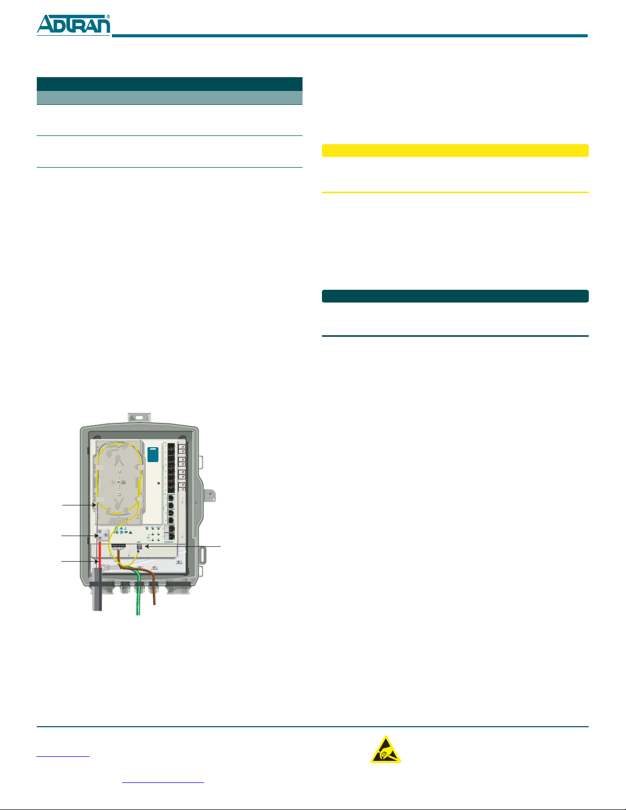
Fiber Installation
To install fiber to the ONT, refer to the illustration below and complete the
following steps:
1. Remove the cover of the Fiber Tray (P/N 3353312-E) and install the
tray using the two #6 screws (P/N 327600051-E) provided.
2. Route the fiber coming to the customer premise through the rubber
grommet as shown.
3. Trim the insulation on the fiber cable back so there is a sufficient
length of fiber to attach the fiber connector to the end of the fiber
cable.
4. Loosen the cable support clamp and route the strength member
through the clamp. Retighten the cable support clamp.
5. Clean all optical surfaces before and after splicing.
6. Splice the fiber to the fiber jumper cable (yellow) using a Fusion-
Type splice. DO NOT use a mechanical splice as this may create a
reflection at the splice point.
7. Connect the fiber jumper cable to the Optical connector at the
bottom of the Electronics Module.
Ethernet LED Connectivity
Label Status Description
LINK 

Off
Green
Link is down or Administratively
shut down
10/100/1000 link is up
ACTIVITY 

Off
Yellow Flashing
No activity, or Administratively
Shut Down
TX or Rx activity
Note: Cable color is for
clarity purposes only.
Fiber
TELEPHONETROUBLESHOOTING:
1.Identify the bad line (POTS 1-8).
2.Plug any working phone into
theappropriatejack.
If the telephone works,the unit
isfunctioningnormally.
If the telephone does not work,
contact your service provider.
3.Remove the telephone from the
POTSjack.
TOTALACCESS372E
1287723G1
LOWBAT
BATMIS
REPBAT
ONBAT
SIGRTN
12VRTN
+12VDC
Cable
Support
Clamp
Strength
Member
(Red)
Active Ethernet
Connecton
Note: POTS, DS1 and Ethernet
Cables have been removed
for clarity purposes.
Local Power Source Wiring
The ONT needs to be powered by a UL Listed Power Supply suitable for
the application with Output at Local Power Supply (LPS) Levels.
Install the UPS
Installation of the Uninterruptible Power Source (P/N 1187735G1) will be
dictated by on-site conditions and local telephone company practices.
CAUTION
!
Use caution when routing wires and cables. Avoid severe bending and
routing over sharp edges. Use grommets when possible to avoid wear on
cable insulation.
1. Install the Uninterruptible Power Source (UPS) cable that runs from
the ONT to the Power/Alarm connector of the UPS via the cus-
tomer provided PVC conduit (or method used by your local tele-
phone company practice).
2. Swing the electronics module closed and tighten the security screw
with the 5/32 Hex tamper proof bit. Do not exceed 20 in lbs of
torque.
3. If necessary, tie wrap both the #6 ground wire and the UPS cable
run to the Buried Fiber Drop riser conduit.
NOTE
Refer to the Total Access 300 Series Small Business Unit Active Ethernet ONT
Installation and Maintenance Guide (P/N 612877SBAONT-5) for testing and
verification information.
OPERATIONAL SPECIFICATIONS
Voltage Range: 12 VDC (nominal) 10.8 VDC to 14.4 (tolerance)
Maximum Current: 2.0 Amp
Dimensions
oHeight: 15.0 inches (38.1 centimeters)
oWidth: 9.75 inches (24.8 centimeters)
oDepth: 4.0 inches (10.1 centimeters)
Weight: 3.5 pounds (1.6 kilograms) ONT and NID combined
oNID Only: 2.25 pounds (1 kilograms)
oElectronics Module: 1.25 pounds (0.57 kilogram)
Operational Temperature: –40°F to 149°F (–40°C to +65°C)
Storage Temperature: –40°F to 185°F (–40°C to +85°C)
Relative Humidity: 95%, noncondensing within enclosure
SAFETY AND REGULATORY COMPLIANCE
RefertotheappropriateTotal Access 300 Series Small Business Unit Active
EthernetSafetyandRegulatoryComplianceNotice(P/N61287723G1‐17for
detailedsafetyandregulatoryinformation.
C A U T I O N
C A U T I O N
!
SUBJECT TO ELECTROSTATIC DAMAGE
OR DECREASE IN RELIABILITY.
HANDLING PRECAUTIONS REQUIRED.
ADTRAN CUSTOMER CARE:
From within the U.S. 1.800.726.8663
From outside the U.S. +1 256.963.8716
PRICING AND AVAILABILITY 1.800.827.0807

Other manuals for Total Access 300 Series

11

This manual suits for next models

4

Other ADTRAN Control Unit manuals

ADTRAN 1200065L1-1 User manual

ADTRAN

ADTRAN 1200065L1-1 User manual

ADTRAN ATLAS 800 Series Module QUAD E1 User manual

ADTRAN

ADTRAN ATLAS 800 Series Module QUAD E1 User manual

ADTRAN Octal BRI/U User manual

ADTRAN

ADTRAN Octal BRI/U User manual

ADTRAN Job Aid+ 1442971GX User manual

ADTRAN

ADTRAN Job Aid+ 1442971GX User manual

ADTRAN SFP GPON ONU User manual

ADTRAN

ADTRAN SFP GPON ONU User manual

ADTRAN Total Access 300 Series User manual

ADTRAN

ADTRAN Total Access 300 Series User manual

ADTRAN E1 User manual

ADTRAN

ADTRAN E1 User manual

ADTRAN NetVanta Octal T1/E1 Wide Module User manual

ADTRAN

ADTRAN NetVanta Octal T1/E1 Wide Module User manual

ADTRAN 1200222L1 User manual

ADTRAN

ADTRAN 1200222L1 User manual

ADTRAN MX2820 SCU User manual

ADTRAN

ADTRAN MX2820 SCU User manual

ADTRAN 1200791L1 User manual

ADTRAN

ADTRAN 1200791L1 User manual

ADTRAN 1442442F1 User manual

ADTRAN

ADTRAN 1442442F1 User manual

ADTRAN OC-48/STM-16 DWDM SFP User manual

ADTRAN

ADTRAN OC-48/STM-16 DWDM SFP User manual

ADTRAN Job Aid+ 1442707G3 User manual

ADTRAN

ADTRAN Job Aid+ 1442707G3 User manual

ADTRAN T200 H2TU-R User manual

ADTRAN

ADTRAN T200 H2TU-R User manual

ADTRAN NetVanta SHDSL User manual

ADTRAN

ADTRAN NetVanta SHDSL User manual

ADTRAN Octal BRI S/T User manual

ADTRAN

ADTRAN Octal BRI S/T User manual

ADTRAN IMUX-56 User manual

ADTRAN

ADTRAN IMUX-56 User manual

ADTRAN Job Aid+ 1442707G1 User manual

ADTRAN

ADTRAN Job Aid+ 1442707G1 User manual

ADTRAN Total Access 300 User manual

ADTRAN

ADTRAN Total Access 300 User manual

ADTRAN TRACER QUAD E1 User manual

ADTRAN

ADTRAN TRACER QUAD E1 User manual

ADTRAN E220 HFAC HDSL Instruction Manual

ADTRAN

ADTRAN E220 HFAC HDSL Instruction Manual

ADTRAN Total Access 1500 Instruction Manual

ADTRAN

ADTRAN Total Access 1500 Instruction Manual

ADTRAN U-BR1TE Instruction Manual

ADTRAN

ADTRAN U-BR1TE Instruction Manual

Popular Control Unit manuals by other brands

Black Box LMC5113C manual

Black Box

Black Box LMC5113C manual

SimCom SIM900 Series Reference Design Guide

SimCom

SimCom SIM900 Series Reference Design Guide

MC Crypt 31 24 81 operating instructions

MC Crypt

MC Crypt 31 24 81 operating instructions

Murrelektronik IMPACT67-P instruction manual

Murrelektronik

Murrelektronik IMPACT67-P instruction manual

Pro-face CA2-ISOALL422-01 installation guide

Pro-face

Pro-face CA2-ISOALL422-01 installation guide

Ublox NEO-6 Integration manual

Ublox

Ublox NEO-6 Integration manual

Delta AX-8 Series user guide

Delta

Delta AX-8 Series user guide

Ban Seok BV-322M user manual

Ban Seok

Ban Seok BV-322M user manual

WHISPER KOOL Ceiling Mount 8000 manual

WHISPER KOOL

WHISPER KOOL Ceiling Mount 8000 manual

Krom Schroder JSAV operating instructions

Krom Schroder

Krom Schroder JSAV operating instructions

Paradox APR3-HUB2 instructions

Paradox

Paradox APR3-HUB2 instructions

IBC control MicroMax370 manual

IBC control

IBC control MicroMax370 manual

Zcom XA-623AH user manual

Zcom

Zcom XA-623AH user manual

GiBiDi GECO LUX GECO60 Instructions for installations

GiBiDi

GiBiDi GECO LUX GECO60 Instructions for installations

Black Box 5 manual

Black Box

Black Box 5 manual

System air PKI-C Series Installation, operation and maintenance manual

System air

System air PKI-C Series Installation, operation and maintenance manual

SIGMA TEK C-DIAS manual

SIGMA TEK

SIGMA TEK C-DIAS manual

Z-World RCM3000 user manual

Z-World

Z-World RCM3000 user manual

manuals.online logo
manuals.online logoBrands
  • About & Mission
  • Contact us
  • Privacy Policy
  • Terms and Conditions

Copyright 2025 Manuals.Online. All Rights Reserved.