GRUPO AUDIO-VIDEO HAV/200
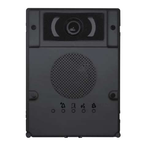
El grupo viene completo de:
- telecámara CCD orientable manual-
mente, tanto en horizontal como en
vertical, de ±11° (fig. 1), con objetivo
de foco fijo (para las dimensiones de la
zona de captación hacer referencia a la
fig. 2);
- grupo fónico (el micrófono es removi-
ble para poder montarlo en posición
remota cuando las características de la
instalación lo requieran);
- LED de infrarrojos para iluminar el
sujeto;
- dos potenciómetros para las siguien-
tes tareas (fig. 3):
ajuste del volumen para la placa
exterior;
ajuste del volumen para el derivado
interno.
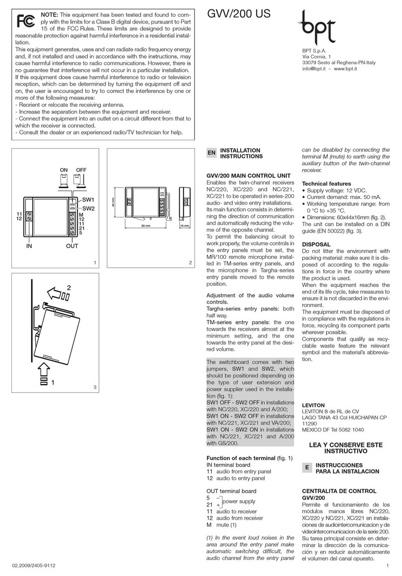
Function of each terminal (fig. 3)
5–14 17.5 VDC
6+ supply voltage
11 audio to receiver
12 audio from receiver
14 enabling
V– negative video signal (1)
V+ positive video signal
V+ video signal (2)
VS video signal shield
Función de los bornes (fig. 3)
5– alimentación
6+ 14÷17,5 VDC
11 audio para el derivado interno
12 audio desde el derivado interno
14 habilitación
V–señal vídeo negativa (1)
V+ señal vídeo positiva
V+ señal vídeo (2)
VS pantalla señal vídeo
(1)Bornes a utilizar cuando la señal
de vídeo es transmitida a través de
par telefónico
(2)Bornes a utilizar cuando la señal
de vídeo es transmitida a través de
cable coaxial
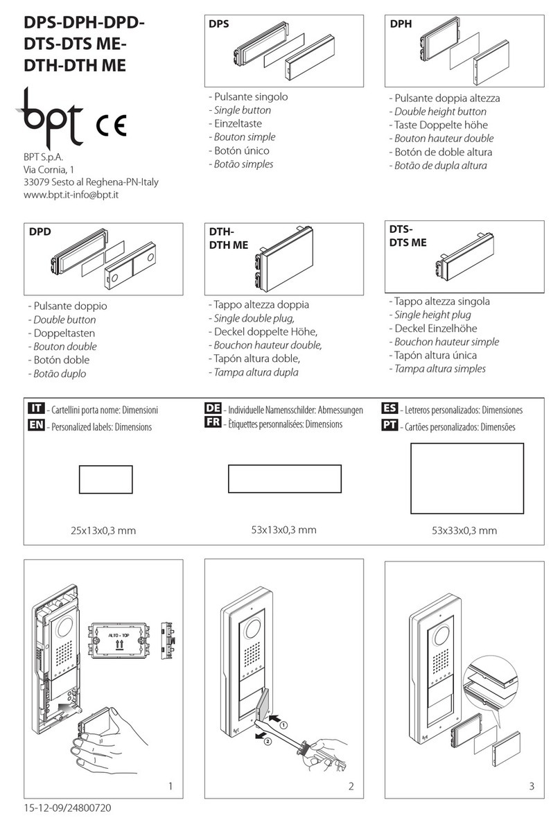
Funciones del puente SW1 (fig. 3)
SW1 en posición C:transmisión de la
señal de vídeo a través de cable
coaxial.
SW1 en posición T:transmisión de la
señal de vídeo a través de par telefóni-
co.
Características técnicas
• Estándar vídeo: EIA (CCIR).
• Sensor: CCD 1/4”.
• Frecuencia horizontal: 15.625 Hz
(15.750 Hz EIA).
•Frecuencia vertical: 50 Hz (60 Hz
EIA).
•Salida vídeo: 1Vpp compuesto en
75 Ω.
• Resolución: 380 líneas.
• Iluminación mínima: 5 lx.
• Relación señal/ruido: 45 dB.
• Obturador: electrónico automático
de 1/50s a 1/100.000s.
• Objetivo: de foco fijo f 3.7 F 4.5.
2
• Alimentación: 14÷17,5 VDC.
• Consumo: 250 mA.
• Temperatura de funcionamiento: de
-15 °C a +50 °C.
GRUPO AUDIO HA/200
El grupo viene completo de:
-altavoz;
- micrófono removible para poder
montarlo en posición remota cuando
las características de la instalación lo
requieran;
-dos potenciómetros para las siguien-
tes tareas (fig. 4):
ajuste del volumen para la placa
exterior;
ajuste del volumen para el derivado
interno
Función de los bornes (fig. 4)
5– alimentación
21 + 12 VDC
8común llamada (para nota testigo)
11 audio para el derivado interno
12 audio desde el derivado interno
14 habilitación
NOTA. En instalaciones en que no
esté previsto el mando de habilita-
ción, es posible conectar el borne 14
amasa (grupo siempre activo) o al
borne 12 (grupo activo cuando se
levanta el auricular).
Características técnicas
• Alimentación: 12 VDC.
•Consumo: 50 mA máx. (35 mA en
reposo).
• Temperatura de funcionamiento: de
-15 °Ca+50 °C.
ELIMINACION
Comprobar que no se tire al me-
dioambiente el material de embalaje,
sino que sea eliminado conforme a las
normas vigentes en el país donde se
utilice el producto.
Al final del ciclo de vida del aparato
evítese que éste sea tirado al
medioambiente.
La eliminación del aparato debe efec-
tuarse conforme a las normas vigentes
yprivilegiando el reciclaje de sus
partes componentes.
En los componentes, para los cuales
está prevista la eliminación con recicla-
je, se indican el símbolo y la sigla del
material.
4
EINSTRUCCIONES
PARA LA INSTALACION
VS
V+
V-
14
12
11
6
5
CT
TC
T
TC
C
SW1
3
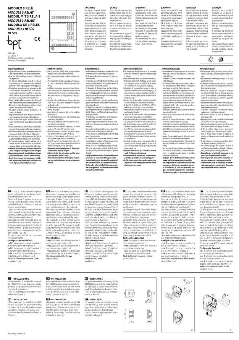
NOTA: este equipo ha sido ensayado y declarado conforme
alos límites establecidos para un dispositivo digital de Clase
B, de acuerdo con el Apartado 15 de las Normas FCC. Estos límites
han sido diseñados para ofrecer una protección razonable contra
interferencias perjudiciales en una instalación residencial.
Este equipo genera, utiliza y puede emitir energía de radiofrecuencia y,
si no se instala y utiliza conforme a las instrucciones, puede crear
interferencias perjudiciales para las radiocomunicaciones. Sin embar-
go, no se garantiza que no se produzcan interferencias en una insta-
lación concreta.
Si este equipo crea interferencias perjudiciales para la recepción de
radio o televisión, lo cual se puede comprobar apagando y encen-
diendo el equipo, se recomienda al usuario que intente corregir la
interferencia adoptando una o varias de las siguientes medidas:
-Modifique la orientación o la posición de la antena receptora.
-Aumente la distancia que separa el equipo del receptor.
-Conecte el equipo a un tomacorriente de un circuito diferente de
aquel al que está conectado el receptor.
-Solicite la asistencia de su distribuidor o de un técnico de radio/TV
cualificado.
LEVITON
LEVITON S de RL de CV
LAGO TANA 43 Col HUICHAPAN CP
11290
MEXICO DF Tel 5082 1040
LEA Y CONSERVE ESTE
INSTRUCTIVO


