AUTOCHAIR Smart Lifter LM User manual
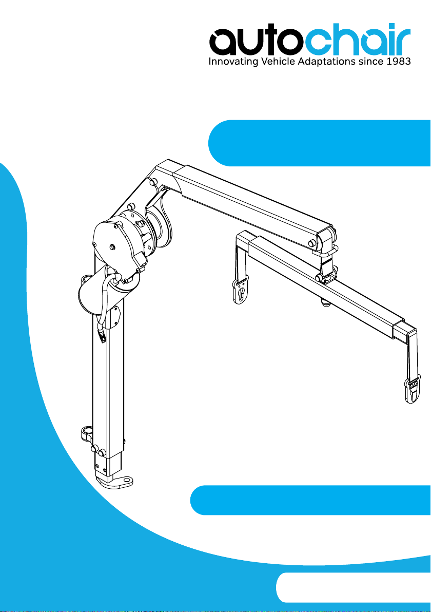
Smart Lifter
User Manual
LM Range
Smart Lifter – LM Range www.autochair.co.uk 2
Safety Guidelines
Copyright © 2017
Autochair Ltd.
1280080 Rev. F
Manufactured By:
Autochair Ltd.
Wood Street North
Meadow Lane Industrial Estate
Alfreton
Derbyshire
DE55 7JR
WARNING! These symbols denote a potentially dangerous situation. Failure
WRFDUU\RXWWKHVSHFL˩HGSURFHGXUHVPD\UHVXOWLQLQMXU\RU
damage to the device.
0$1'$725<7KHLQGLFDWHGDFWLRQVPXVWEHFDUULHGRXWDVVSHFL˩HG)DLOXUHWR
SHUIRUPWKHVSHFL˩HGDFWLRQVPD\UHVXOWLQLQMXU\RUGDPDJHWR
the device.
PROHIBITED! Do not carry out the indicated actions. They should not be
performed at any time, under any circumstances. Carrying out a
SURKLELWHGDFWLRQPD\UHVXOWLQLQMXU\RUGDPDJHWRWKHXQLW
The following symbols are used to identify warnings and important details throughout this
manual. Please read them and ensure you are aware of their meaning.
127(7KLVPDQXDOLVFRPSLOHGIURPWKHODWHVWVSHFL˩FDWLRQVDQGSURGXFWLQIRUPDWLRQDYDLODEOHDWWKH
time of publication. We reserve the right to make changes as they become necessary. Any changes
to our products may cause slight variations between the illustrations and explanations in this manual.
The latest/current version of this manual is available on our website.
3OHDVH˩OORXWWKHIROORZLQJGHWDLOVIRUTXLFNUHIHUHQFH
Autochair Dealer:
Address:
Phone Number: Purchase Date:
Serial Number:
WARNING! The Smart Lifter is only intended to be installed by an Accredited
Autochair Dealer or an Autochair installer. Do not attempt to install the
Smart Lifter yourself.

Smart Lifter – LM Range www.autochair.co.uk 3
Contents
1. INTRODUCTION ..........................................................................................................4
2. SAFETY ..........................................................................................................................5
3. TECHNICAL ..................................................................................................................9
4. OPERATION ..................................................................................................................13
5. REMOVING & REPLACING ........................................................................................19
6. TROUBLESHOOTING ..................................................................................................21
7. CARE & MAINTENANCE .............................................................................................22
8. WARRANTY ...................................................................................................................23

Smart Lifter – LM Range www.autochair.co.uk 4
1. Introduction
Congratulations on the purchase of your new Smart Lifter manufactured by Autochair Ltd
Please read through these instructions thoroughly before operating your Smart Lifter.
All models of this product are very powerful in both the UP (lifting) and DOWN (lowering) and for 4-way
version; also the IN (into vehicle) and OUT (out of vehicle) operation. Care should be taken that the boom and
the mobility product that is being lifted is free to move. These devices have the power to break trim and cause
harm if not operated correctly.
This Smart Lifter is designed to lift wheelchairs, electric wheelchairs and scooters into vehicles. They should
EH˩WWHGLQWRWKHYHKLFOHE\DFRPSHWHQW˩WWHUZKRZLOODOVRHQVXUHWKDWWKHFRUUHFWOLIWLQJEUDFNHWLV˩WWHGWR
VXLW\RXUPRELOLW\YHKLFOH7KH˩WWHUZLOODOVRGHPRQVWUDWHWKHRSHUDWLRQRI\RXU6PDUW/LIWHUDQGVKRZ\RXKRZ
the lifting brackets are connected.
Please note that your Smart Lifter comes complete with a 12 month warranty. This warranty covers the
replacement of any faulty parts and the labour for replacing those parts. The warranty does not cover travel
costs.
ONLINE AND PRIVATE PURCHASES
,I\RXSXUFKDVHG\RXUSURGXFWRQOLQHRUIURPDSUHYLRXVRZQHUDQGUHTXLUHDQ\LQIRUPDWLRQDERXWWKHVDIH
use and maintenance of your Smart Lifter, please visit our website at www.autochair.co.uk or contact your
Accredited Autochair Dealer.
END-USER’S AGREEMENT
By accepting delivery of this Smart Lifter, you agree that you will not modify, change or alter this product or
remove or render inoperable or unsafe any guards, shields, or other safety features of this product; fail, refuse,
RUQHJOHFWWRLQVWDOODQ\UHWUR˩WNLWVIURPWLPHWRWLPHSURYLGHGE\$XWRFKDLUWRHQKDQFHRUSUHVHUYHWKHVDIH
use of this product.
DELIVERY AND SHIPPING
Before using or operating your Smart Lifter, make sure your delivery is complete. Some components may be
individually packaged. If you do not receive a complete delivery or if any damage has occurred to the product
or packaging whilst in transit, please contact your Accredited Autochair Dealer. Upon delivery of your new
product your Accredited Autochair Dealer should provide a demonstration on the correct use of the Smart
Lifter.
FEEDBACK AND SUGGESTIONS
:HZDQWWRKHDU\RXUTXHVWLRQVFRPPHQWVDQGVXJJHVWLRQVDERXWWKLVPDQXDO:HZRXOGDOVROLNHWR
hear about the safety and reliability of your new Smart Lifter and about the service you received from your
Accredited Autochair Dealer.
Please notify us of any change of address, so we can keep you apprised of important information about
safety, new products, and new options that could improve your ability to use and enjoy your lift system. Please
feel free to contact us at the address below:
Manufactured By:
Autochair Ltd.
Wood Street North
Meadow Lane Industrial Estate
Alfreton
Derbyshire
DE55 7JR
0800 009 2326
www.autochair.co.uk
Smart Lifter – LM Range www.autochair.co.uk 5
2. Safety
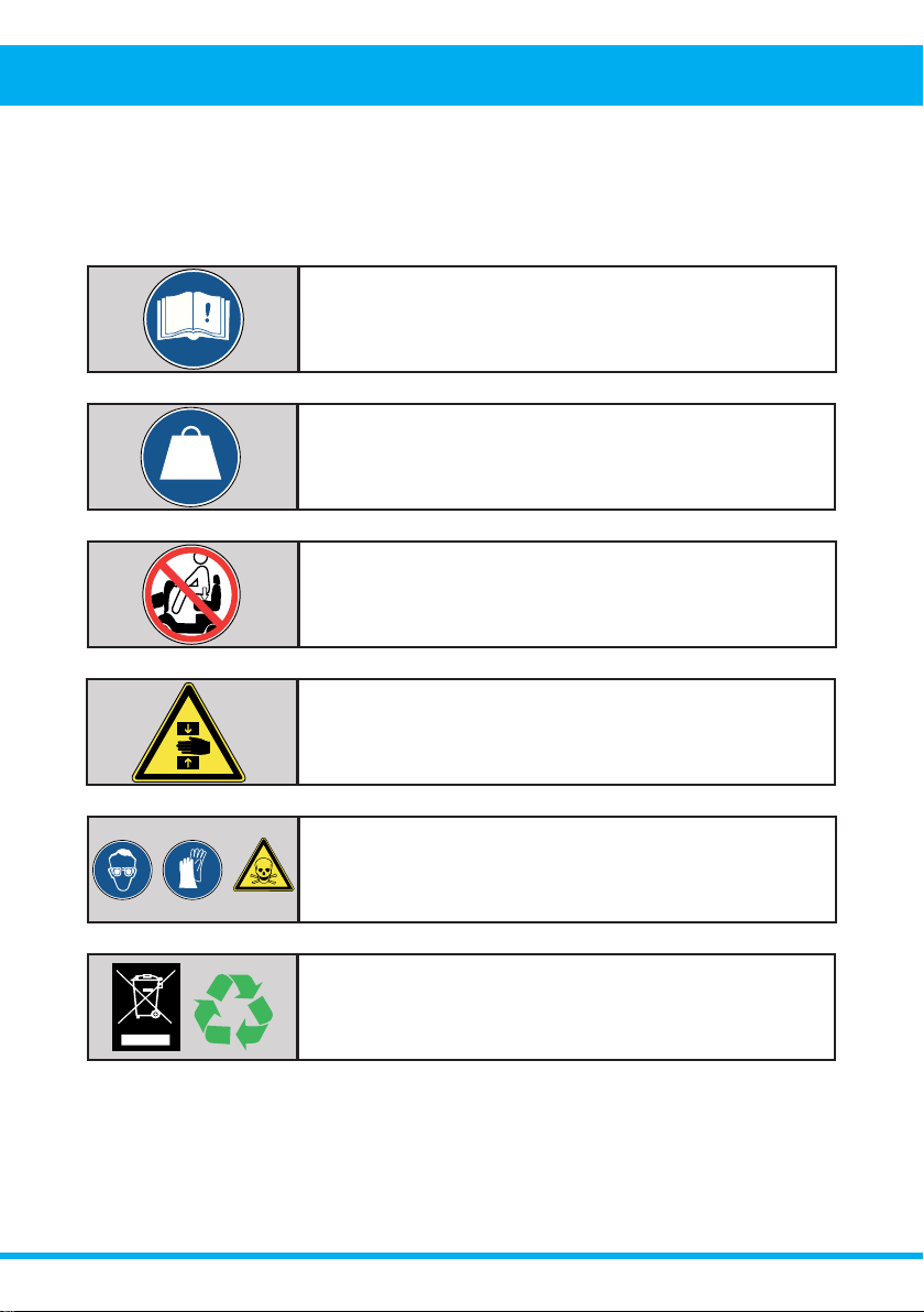
Product Safety Symbols
Please study the symbols below to ensure you understand them completely. They are used on the
Smart Lifter and in the manual to identify warnings and mandatory or prohibited actions.
Disposal and recycling. Contact your Accredited Autochair Dealer
for information on proper disposal of your Smart Lifter and its
packaging.
Do not ride on the mobility product while operating the Smart
Lifter or when the vehicle is in motion.
Battery posts, terminals and related accessories contain lead
and lead compounds. Wear goggles and gloves when handling
batteries and wash hands after handling.
Maximum lifting capacity.
MAX
--- kgs
3LQFK&UXVKSRLQWVRQWKH6PDUW/LIWHU.HHSKDQGVDQG˩QJHUV
away from moving components and crush points when operating
the Smart Lifter.
Read and follow all directions in this manual.
Smart Lifter – LM Range www.autochair.co.uk 6
LIFTING CAPACITIES
This Smart Lifter is designed to lift a maximum weight of 40kg or 80kg depending on the version you have
installed in your vehicle. Check this by referring to labels on the boom. Under no circumstances should the
Smart Lifter exceed the stated lifting capacity. Subjecting the Smart Lifter to the strain of lifting more than it
is designed to may cause it to fail, resulting in damage to the mobility product and/or injury to the operator.
5HIHUWRWKHPRELOLW\SURGXFWVSHFL˩FDWLRQVIRULQIRUPDWLRQRQWKHRYHUDOOZHLJKWRIWKHPRELOLW\SURGXFWEHIRUH
lifting with the Smart Lifter.
PRE-USE INSPECTION
7KHUHVKRXOGEHQRVKDUSHGJHVRQWKH6PDUW/LIWHUWKH3RVW$)UDPHRUWKHOLIWLQJEUDFNHW,I\RX˩QG
any sharp edges, please contact your Accredited Autochair Dealer and notify them. Make sure that you
are completely happy with the operation of your Smart Lifter before lifting your mobility device. Misuse or
incorrect operation of the Smart Lifter could result in injury. Inspect the lifting straps before every use for
twisting, fraying or signs of wear. If signs of wear become evident, have them replaced by your Accredited
Autochair Dealer.
OPERATOR POSITIONING
The operator should stand a safe distance from the Smart Lifter when it is in operation to ensure that their
IHHWDUHQHYHUSRVLWLRQHGXQGHUDUDLVHGPRELOLW\SURGXFW)RUWKHZD\YHUVLRQNHHSKDQGVDQG˩QJHUVFOHDU
of the Smart Lifter when loading the mobility product in and out of the vehicle.
2. Safety
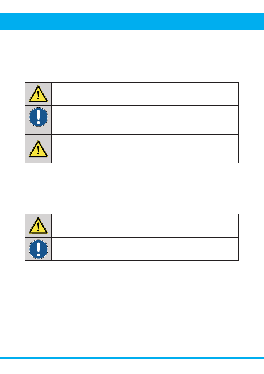
WARNING! ([FHHGLQJWKHPD[LPXPOLIWLQJFDSDFLW\RI\RXUVSHFL˩F6PDUW/LIWHU
may cause the lift system to fail, resulting in injury to the operator and
damage to the Smart Lifter.
MANDATORY! $GGLQJDFFHVVRULHVRYHUVL]HGEDWWHULHVRUDGL˨HUHQWVHDWZLOO
increase the weight of your mobility device. Verify with your mobility
device supplier to ensure your mobility device does not exceed the
maximum lift capacity of the Smart Lifter.
WARNING! The Fitting Kit and Accessories for your vehicle may be rated at
a lower capacity than your Smart Lifter. Please check with your
Accredited Autochair Dealer to ensure the correct Safe Working Load
is maintained.
WARNING! A frayed or worn strap can snap, resulting in damage to the Smart
Lifter and mobility device and potentially injury to the operator.
MANDATORY! If your scooter or mobility device model changes, please contact your
$FFUHGLWHG$XWRFKDLU'HDOHUWRFRQ˩UPVXLWDELOLW\ZLWK\RXUH[LVWLQJ
Smart Lifter before use.

Smart Lifter – LM Range www.autochair.co.uk 7
2. Safety
VEHICLE POSITIONING
%HVXUH\RXUYHKLFOHLVSDUNHGRQ˪DWOHYHOJURXQGDQGWKHKDQGEUDNHLVHQJDJHGEHIRUHDWWHPSWLQJWROLIW
a mobility product. Before lowering ensure that the Smart Lifter is fully out of the vehicle, otherwise your
mobility device may come into contact with your vehicles bumper.
%HIRUHOLIWLQJWKHPRELOLW\SURGXFWIRUWKH˩UVWWLPHRSHUDWHWKH6PDUW/LIWHUZLWKRXWDORDGXQWLO\RX
are familiar with the controls and how the Smart Lifter operates.
Any adjustment to the Smart Lifter settings must only be carried out by an Accredited Autochair Dealer. Your
Smart Lifter should be serviced every year to ensure it is in good working order.
If in doubt about any aspect of your Smart Lifter, please contact your Accredited Autochair Dealer.
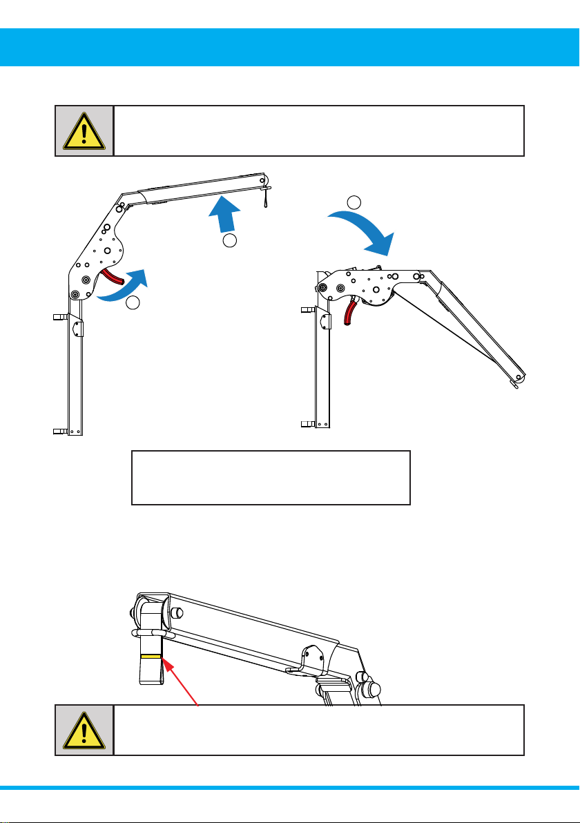
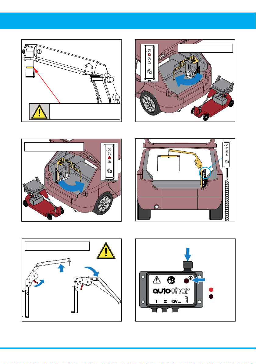
WARNING! Do not lift the Smart Lifter pass the Yellow stitching on the webbing
strap. Lifting past this point can cause damage to the Smart Lifter
motor and may result in Smart Lifter failure.
WARNING! 7KHVDIHW\5FOLSPXVWEH˩WWHGLQWRWKHWRSSLQLQWKHSRVW$)UDPH
before operating..
WARNING! For folding versions of the Smart Lifter; Never use the Smart Lifter
when in the folded position.
WARNING! The Smart Lifter must never be operated by a child or any person not
deemed appropriate by the technician who installed it.
WARNING! Attempting to lift a mobility product when a vehicle is not on level
ground will cause the mobility product to swing toward or away from
WKHYHKLFOHPDNLQJLWGLI˩FXOWWRJHWWKHPRELOLW\SURGXFWLQWRWKH
vehicle, especially for the 2-way version.
WARNING! Note the position of all pinch point warning labels stating
“Keep Clear”. Never place your hands in these locations when the
Smart Lifter is in operation.
WARNING! Never use a Smart Lifter that has signs of damage or excessive wear.
WARNING! Do not exceed the maximum stated lifting capacity.
WARNING! Misuse of the Smart Lifter may result in serious injury and damage to
the unit or vehicle.
Smart Lifter – LM Range www.autochair.co.uk 8
2. Safety
WARNING! Do not lift the Smart Lifter pass the Yellow stitching on the webbing
strap. Lifting past this point can cause damage to the Smart Lifter
motor and may result in Smart Lifter failure.
1. Lift the arm.
2. Pull the lever to release latch.
3. Lower the arm to its horizontal locking position.
1
2
3
WARNING! Never use the Smart Lifter when in the folded position.

Smart Lifter – LM Range www.autochair.co.uk 9
3. Technical
Smart Lifter Type
7KHUHDUHVHYHUDOFRQ˩JXUDWLRQVWKDWDUHDYDLODEOHIRUWKLV6PDUW/LIWHUGHSHQGLQJRQWKHZHLJKWUDWLQJNJ
RUNJFRQWUROW\SHZD\RUZD\PRXQWLQJPHWKRGSRVWRU$IUDPHDQGERRPW\SH˩[HGRUIROGLQJ
Weight Rating
There are two versions of the Smart Lifter; one that has a maximum lifting capacity of 40kg and one that has
a maximum lifting capacity of 80kg. There is a weight rating sticker at the top of each Smart Lifter, which your
mobility device should not exceed. If your mobility device changes; please contact your Accredited Autochair
Dealer to ensure that the mobility device is within the Smart Lifter’s weight capacity and to arrange a new
OLIWLQJEUDFNHWWREH˩WWHG
7KHFRQWUROER[RQDOOQHZ0LQL6PDUW/LIWHUPRGHOVKDYHEHHQPRGL˩HGWRLQFRUSRUDWHDUHVHWWDEOHIXVH7KH
motors used on the Smart Lifter can be overworked and potentially stall or overheat when the webbing (and
spreader bar) pass over the Yellow Line and jams on the horizontal boom.
If the webbing does pass over the Yellow Line, the auto resettable fuse will blow and power will be cut to the
Smart Lifter until it resets. This will take approximately 8 seconds before the power resumes.
The fuses are colour coded depending on the weight capacity of the Smart Lifter, where the 40kg uses a
15Amp Blue fuse and the 80kg uses a 20Amp Yellow. These fuses are located on the left hand side of the
control box and are not removable.
A separate fuse is also connected to the car battery through an in-line fuse holder and can be replaced if
blown. A spare fuse will be provided as part of your installation. For these fuses; the 40kg uses a 25Amp and
the 80kg uses a 30Amp.

Smart Lifter – LM Range www.autochair.co.uk 10
3. Technical
Model 40kg 80kg
Lifting arm weight 6kg 6kg
Maximum lifting capacity 40kg 80kg
Power supply 12V DC
PRODUCT SPECIFICATIONS
Spreader Bar
The spreader bar is used to connect the Smart Lifter to your mobility device (using a lifting bracket). There are
two types of spreader bar connectors; a key hole type and a clipping type (called Karabiners). The Karabiner
W\SHLVPRUHSUHIHUDEOHZKHQKDQGRU˩QJHUIXQFWLRQRIWKHXVHULVUHGXFHG
Spreader Bar with Key Hole Lifting
Points
Spreader Bar with Karabiner Lifting
Points
Mounting Method
Dependant on the vehicle this Smart Lifter is being installed into; it can be mounted either on a Post or an
A-frame for both weight capacities.
Post A-Frame
Retaining Pin
(R-Clip)
Retaining Pin
(R-Clip)
Smart Lifter – LM Range www.autochair.co.uk 10 Smart Lifter – LM Range www.autochair.co.uk 11
3. Technical 3. Technical
Left Hand Side Motor
Boom Type
The boom can be Fixed or Folding. The folding version can reduce the height of the Smart Lifter by up to
325mm (12.8 inches). This is especially important for smaller or hatchback type vehicles; where it wouldn’t be
possible to close the boot with the Smart Lifter in its erect position.
Note: the Smart Lifter should NEVER be used when in the folded position.
Mounting Side
Dependant on the vehicle; the Smart Lifter can be placed on the Right hand side or the Left hand side and as
such the motor can be mounted either side.
Right Hand Side Motor
Folding Boom Fixed Boom

Smart Lifter – LM Range www.autochair.co.uk 12
3. Technical
Control Type
7KHUHDUHWZRFRQWUROW\SHVDZD\RUDZD\DQGDVVXFKWZRGL˨HUHQWKDQGVHWDQGFRQWUROOHUV7KHZD\
version lifts the mobility device up from ground level to the boot height and vice versa for the lowering the
mobility device down from the boot to ground level.
The 4 way version has the added capability to move the mobility device (once it has reached boot height) in
to the vehicle and vice versa for moving the mobility device out of the vehicle (using an In/Out actuator). This
motion has to be completed manually on the 2 way version.
In/Out
Actuator
Handset
(4 Way)
Control Box
(4 Way)
Resettable
Fuse
40kg
80kg
15Amp
20Amp
Note: These
fuses are not
removable.
Handset
(2 Way)
Control Box
(2 Way)
Resettable
Fuse
40kg
80kg
15Amp
20Amp
Note: These
fuses are not
removable.
4 Way Control 2 Way Control
In/Out Actuator
Plate
4. Operation - Loading

Smart Lifter – LM Range www.autochair.co.uk 12 Smart Lifter – LM Range www.autochair.co.uk 13
3. Technical 4. Operation - Loading
1
2
Power Button
Power status
indicator light
Power On
Power O˨
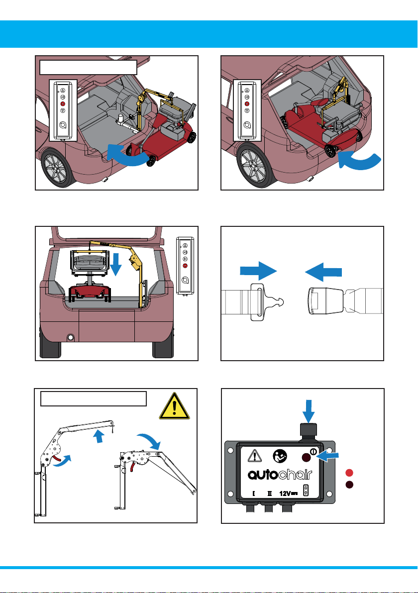
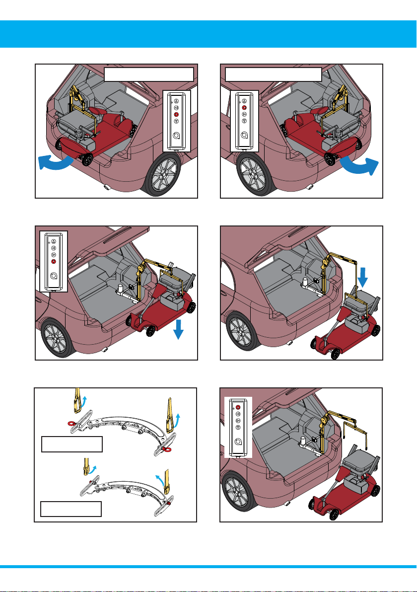
6. Press and hold the LEFT button to swing the Smart
Lifter outwards. Release the button when the boom
is at its outermost position. This has to be done
manually for a 2 way version of the Smart Lifter.
5. Press and hold the RIGHT to swing the Smart
Lifter outwards. Release the button when the boom
is at its outermost position. This has to be done
manually for a 2 way version of the Smart Lifter.
&RQ˩JXUHWKHPRELOLW\GHYLFHIRUOLIWLQJDV
recommended by the product demonstrator or
installer.
3. Locate and pick up the handset from its stored
position.
2. Press the power button to switch on the unit. This
will be indicated by a red light when switched on.
1. Before operating the Smart Lifter; ensure its in the
upright position. Pull the lever to release latch (1)
and raise the boom (2) to its locked upright position.
LOADING A MOBILITY DEVICE
Left Hand Installs Right Hand Installs
Folding Version ONLY

Smart Lifter – LM Range www.autochair.co.uk 14
4. Operation - Loading
12. Press and hold the LEFT button to move the
mobility device inwards. Rotate the mobility device
as it moves inwards. This has to be done manually
for a 2 way version of the Smart Lifter.
11. Release the up button once the mobility device is
DERYHWKHOXJJDJHDUHD˪RRU
9. Engage the keyhole plates/karabiner clips
securely to the lifting bracket. DO NOT attempt to lift
without all lifting straps securely connected.
10. Press and hold the up button to raise the mobility
device from the ground.
8. Press and hold the down button to lower the
spreader bar.
7. Position the mobility device so that the lifting
points directly beneath the spreader bar.
Left Hand Installs
Keyhole Plates
Karabiner Clips
Do not lift pass the Yellow
stitching on the webbing strap.
4. Operation - Loading
Smart Lifter – LM Range www.autochair.co.uk 14 Smart Lifter – LM Range www.autochair.co.uk 15
4. Operation - Loading
1
2
3
14. Guide the mobility device into the boot, ensuring
WKHUHLVDGHTXDWHFOHDUDQFHIRUWKHERRPDQG
mobility device to swing into position.
13. Press and hold the RIGHT button to move the
mobility device inwards. Rotate the mobility device as
it moves inwards. This has to be done manually for a
2 way version of the Smart Lifter.
15. Press and hold the down button until the mobility
GHYLFHLV˩UPO\SODFHGRQWRWKH˪RRURIWKHYHKLFOH
and the straps become loose enough to detach.
,I˩WWHG\RXVKRXOGHQJDJHWKHUHVWUDLQWV\VWHP
now.
17. Lift the arm (1) before pulling the lever to release
latch (2) and then lowering the boom (3) to ensure
DGHTXDWHVSDFHWRFORVH\RXUFDUERRW
Right Hand Installs
Power Button
Power status
indicator light
Power On
Power O˨
18. Return the handset to its stored position,
ensuring the cable is clear of trapping points. Press
WKHSRZHUEXWWRQWRVZLWFKWKHXQLWR˨
Folding Version ONLY
Smart Lifter – LM Range www.autochair.co.uk 16
4. Operation - Unloading
1
2
Power Button
Power status
indicator light
Power On
Power O˨
5. Press and hold the up button to raise the mobility
GHYLFHIURPWKHYHKLFOH˪RRU
6. Release the up button once the mobility device
has reached its uppermost position.
4. Locate and pick up the handset from its stored
position.
3. Press the power button to switch on the unit. This
will be indicated by a red light when switched on.
2. Before operating the Smart Lifter; ensure its in the
upright position. Pull the lever to release latch (1)
and raise the boom (2) to its locked upright position.
,I\RXKDYHDUHVWUDLQWV\VWHP˩WWHGWKLVVKRXOG
˩UVWEHGLVHQJDJHG
UNLOADING A MOBILITY DEVICE
4. Operation - Unloading
Folding Version ONLY
Smart Lifter – LM Range www.autochair.co.uk 16 Smart Lifter – LM Range www.autochair.co.uk 17
4. Operation - Unloading
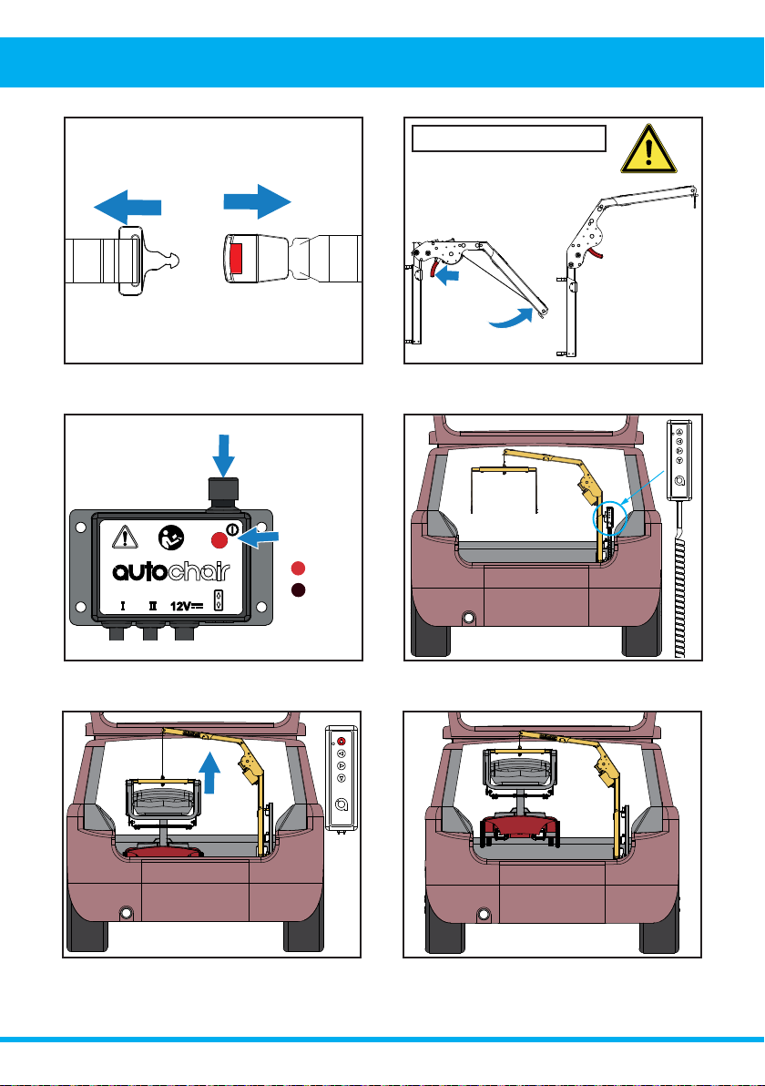
11. Release the key hole plates/karabiner clips from
the lifting bracket.
12. Ensure the mobility device is free from the Smart
Lifter. Press the up button to raise the spreader bar
fully upwards.
10. Release the down button once the mobility
device is grounded and there is some slack in the
lifting straps.
9. Press and hold the down button to lower the
mobility device.
8. Press and hold the LEFT to swing the Smart Lifter
outwards. This has to be done manually for a 2 way
version of the Smart Lifter.
7. Press and hold the RIGHT to swing the Smart
Lifter outwards. This has to be done manually for a 2
way version of the Smart Lifter.
Left Hand Installs Right Hand Installs
Keyhole Plates
Karabiner Clips
Smart Lifter – LM Range www.autochair.co.uk 18
4. Operation - Unloading
15. Press and hold the RIGHT to move the Smart
Lifter inwards. This has to be done manually for a 2
way version of the Smart Lifter.
14. Press and hold the LEFT button to move the
Smart Lifter inwards. This has to be done manually
for a 2 way version of the Smart Lifter.
13. Release the up button before the Yellow marked
line.
16. Return the handset to its stored position,
ensuring the cable is clear of trapping points or
hazards.
Left Hand Installs
1
2
3
17. Fold the boom down by lifting the arm (1) then
pulling the lever to release latch (2) and then lower
the boom to its horizontal locking position (3).
Right Hand Installs
Do not lift pass the Yellow
stitching on the webbing strap.
5. Removing & Replacing
Power Button
Power status
indicator light
Power On
Power O˨
3UHVVWKHSRZHUEXWWRQWRVZLWFKR˨WKHXQLW7KH
light should no longer be illuminated indicating the
XQLWLVVZLWFKHGR˨
Folding Version ONLY

Smart Lifter – LM Range www.autochair.co.uk 18 Smart Lifter – LM Range www.autochair.co.uk 19
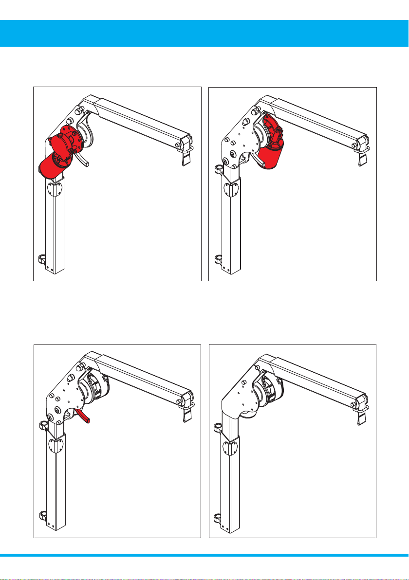
5. Removing & Replacing
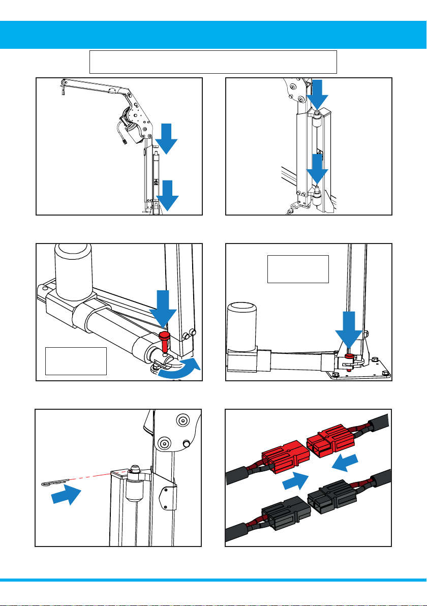
6. Store the Smart Lifter in a dry, safe place when
not in use.
5. Slide the Smart Lifter upwards to remove it from
the mounting lugs. TAKE CARE when lifting.
4. Rotate the actuator away from the bottom post
and remove the actuator pin.
3. Partially remove the actuator pin.
2. Remove the Retaining Pin (R-Clip) from the top
pin.
1. Turn the power OFF and unclip the red (4 Way
Version ONLY) and black connectors. DO NOT pull
apart by the wires. This will damage the connectors.
REMOVING
4 Way Version
ONLY
4 Way Version
ONLY
NOTE: The following illustrations show the steps for the post
version. These steps also apply to A-Frame versions.
Smart Lifter – LM Range www.autochair.co.uk 20
5. Removing & Replacing
1. Continued - Ensure both pins are located on their
respective lugs.
1. Rest the upper mounting lug onto the longer
upper pin before aligning the lower pin. The Smart
Lifter should slide smoothly down into place.
2. Half engage the actuator pin. Rotate the Smart
Lifter and align the bottom mount with the actuator
arm.
3. Fully engage the actuator pin by pushing it all the
way down. This will secure the in/out actuator.
6. Connect the red (4 Way Version ONLY) and
black connectors.
4. IMPORTANT - Fully insert the Retaining Pin (R-Clip)
into the top pin.
REPLACING NOTE: The following illustrations show the steps for the post
version. These steps also apply to A-Frame versions.
4 Way Version
ONLY
4 Way Version
ONLY
Table of contents
Other AUTOCHAIR Automobile Accessories manuals


