AUTODIAGGER AD100+ User manual

Autodiagger AD100+
User Manual

1
Introduction
The Autodiagger AD100+ is a handheld tester that is used to test and diagnose alternator charging
problems by replicating the digital signals from a vehicle’s ECU. The AD100+ tester can test an
alternator while it is still installed on a vehicle or on a testbench.
The tester can provide information on whether the alternator’s voltage regulator can communicate
correctly with the vehicle’s ECU and if the alternator responds correctly to the tester’s simulated ECU
input parameters.
The AD100+ can now be updated by NFC from a compatible Android mobile phone or by returning it
to Wood Auto for the update procedure.
Regulator Testing Protocols:
COM, LIN, BSS(BSD) Mercedes, Opel,Audi, BMW, Renault,VW, Ford
24V LIN GRC Mercedes
SIG Ford,Volvo, Mazda
P-D Mazda
L-RVC GM,Vauxhall, Opel
RLO Toyota
iSTARS Combined Alternator-Starters PSA *
* an optional software upgrade is required
Lead Colour Code and Description
RC (Green) COM signal connection.
M (Blue) DFM digital eld monitor.
B+ (Red) Battery positive in tested circuit, tester power supply.
B- (Black) Battery negative in tested circuit, tester ground.

2
Device Operation
The device powers on automatically after connecting power to the B+ and B- leads. The test subject
selection menu will then appear. The desired parameter is selected by pressing the and buttons
and conrmed by a short press on the OK button to enter the testing mode.
After pressing OK, the display will present the following information:
1. voltage of the tested circuit (large digits)
2. required voltage (small digits on the top of the display)
3. alternator load DF/DFM (%)
The green RC and blue M cables should be connected to the correct pins in the voltage regulator’s
socket. Some of the regulators may require connecting other signals (usually B+) with a separate cable
to operate correctly.
The blue M cable can be left disconnected when testing in COM mode.
In the testing mode, buttons and will change the required voltage value. It should be monitored
whether changing the required voltage causes a corresponding change in the alternator/regulator output,
and whether the DFM reading matches the actual state.
Press and hold the OK button to leave the testing mode and return to the selection menu.

3
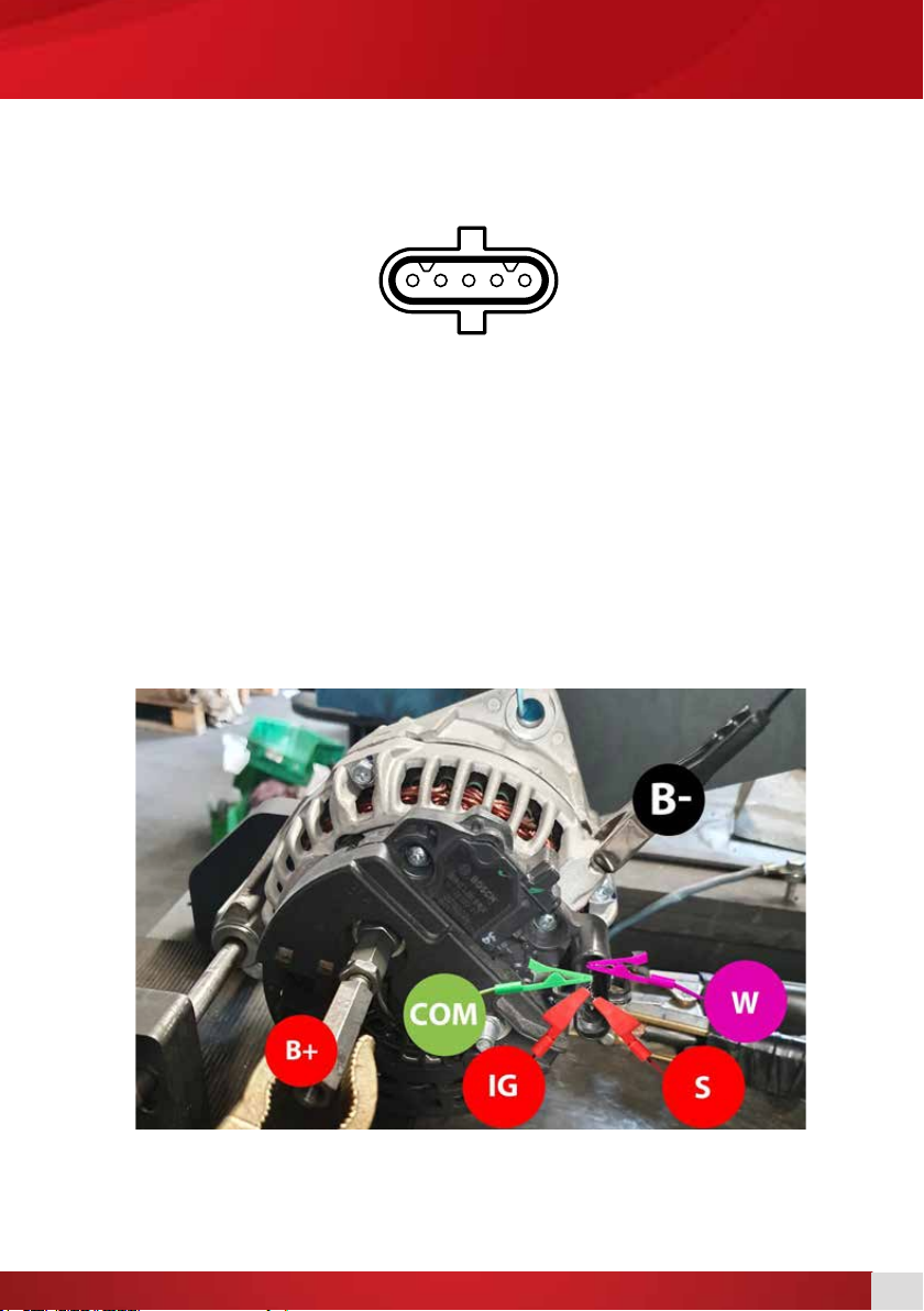
COM, LIN, BSS Testing
Mercedes, Opel,Audi, BMW, Renault,VW, Ford
Alternator Connection:
COM pin RC (Green)
DFM pin M (Blue)
B+ connector B+ (Red)
Alternator bracket/casing B- (Black)
COM, LIN, BSS TestingDevice Operation
COM DFM
COM/LIN
COM/LIN2
LIN2
COM LIN
4
COM, LIN, BSS Testing
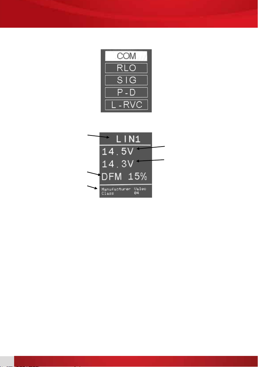
Select the COM function from the main menu and conrm by pressing the OK button:
The device will go into the COM testing mode and display the following information:
During the test, after starting the alternator drive, the actual voltage value should correspond to the
required value and the DFM value should correspond to the current alternator load.
Some discrepancies between the voltage values are acceptable. What is important is the appropriate
reaction of the alternator – increasing or decreasing the output voltage according to the required
voltage.
Selected function
DFM value
Additional information
Required voltage
Actual voltage
5
COM, LIN, BSS Testing LIN 24V Testing
LIN 24V Testing GRC
Mercedes
Alternator connection:
W pin Existing tachometer connection.
LIN pin RC (Green)
15 pin (IG) Existing 15 / ignition connection.
S pin (Battery Sense) Existing S / battery sense connection.
DFM pin Leave disconnected.
B+ connection 24V B+ (Red)
Alternator bracket/casing 24V B- (Black)
The M (Blue) is left disconnected when testing.
The connection of the S, 15(IG), and W pins are connected independently of the AD100+, by using the
connectors located in the vehicle or on the testbench.
W LIN 15 S DFM
6
LIN 24V Testing Ford SIG Testing
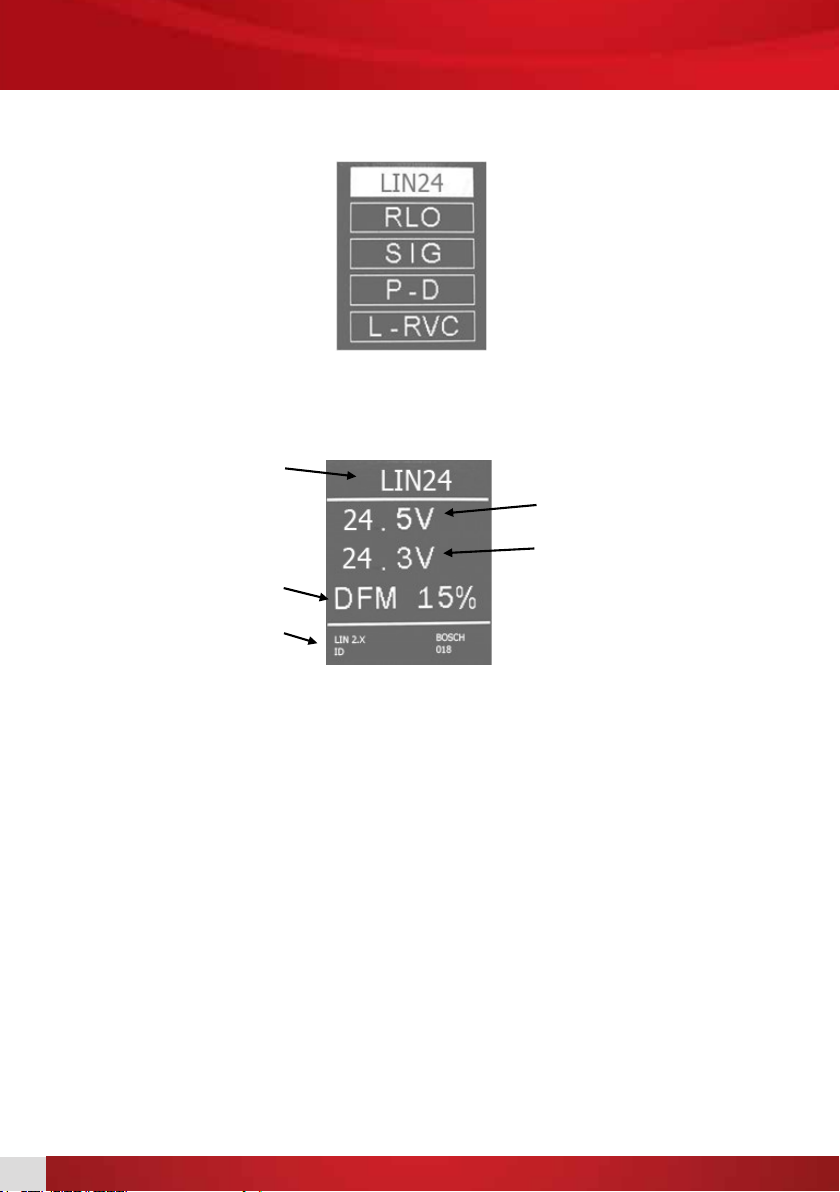
Select the LIN24 function from the main menu and conrm by pressing the OK button.
The device will go into the LIN24 testing mode and display the following information:
During the test, after starting the alternator drive, the actual voltage value should correspond to the
required value and the DFM value should correspond to the current alternator load.
Some discrepancies between the voltage values are acceptable. What is important is the appropriate
reaction of the alternator – increasing or decreasing the output voltage according to the required
voltage.
Selected function
DFM value
Additional information
Required voltage
Actual voltage
7
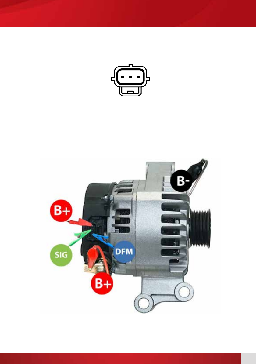
LIN 24V Testing Ford SIG Testing
Ford SIG Testing
Ford, Mazda,Volvo
SIG
FR S
Alternator connection:
FR pin M (Blue)
SIG pin RC (Green)
S pin Existing S / battery sense connection
B+ connection B+ (Red)
Alternator bracket/casing B- (Black)
The connection of the S pin is connected independently of the AD100+, by using the connectors located
in the vehicle or on the testbench.
8
Ford SIG Testing
During the test, after starting the alternator drive, the actual voltage value should correspond to the
required value and the DFM value should correspond to the current alternator load.
Some discrepancies between the voltage values are acceptable. What is important is the appropriate
reaction of the alternator – increasing or decreasing the output voltage according to the required
voltage.
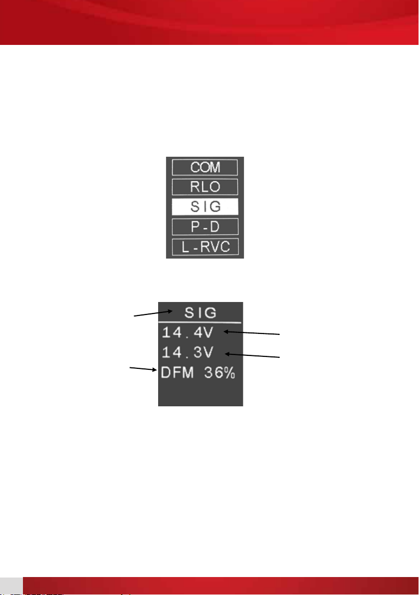
After connecting the testing device, the main menu will appear on the display:
Select the SIG function and conrm by pressing the OK button. The device will go into the SIG testing
mode and display the following information:
Selected function
DFM value
Required voltage
Actual voltage

9
Mazda P-D TestingFord SIG Testing
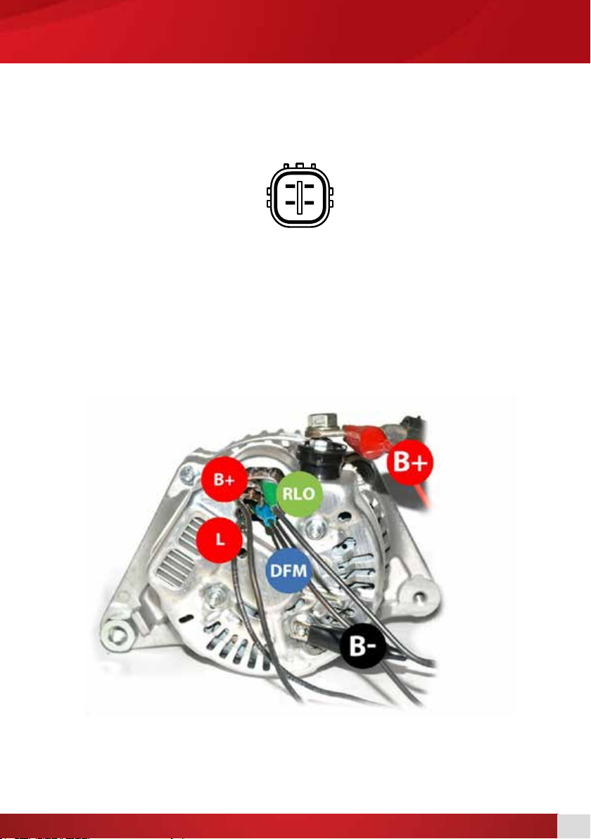
Mazda P-D Testing
Mazda
Alternator connection:
D pin RC (Green)
P pin M (Blue)
B+ connection B+ (Red)
Alternator bracket/casing B- (Black)
D P D P
10
Mazda P-D Testing
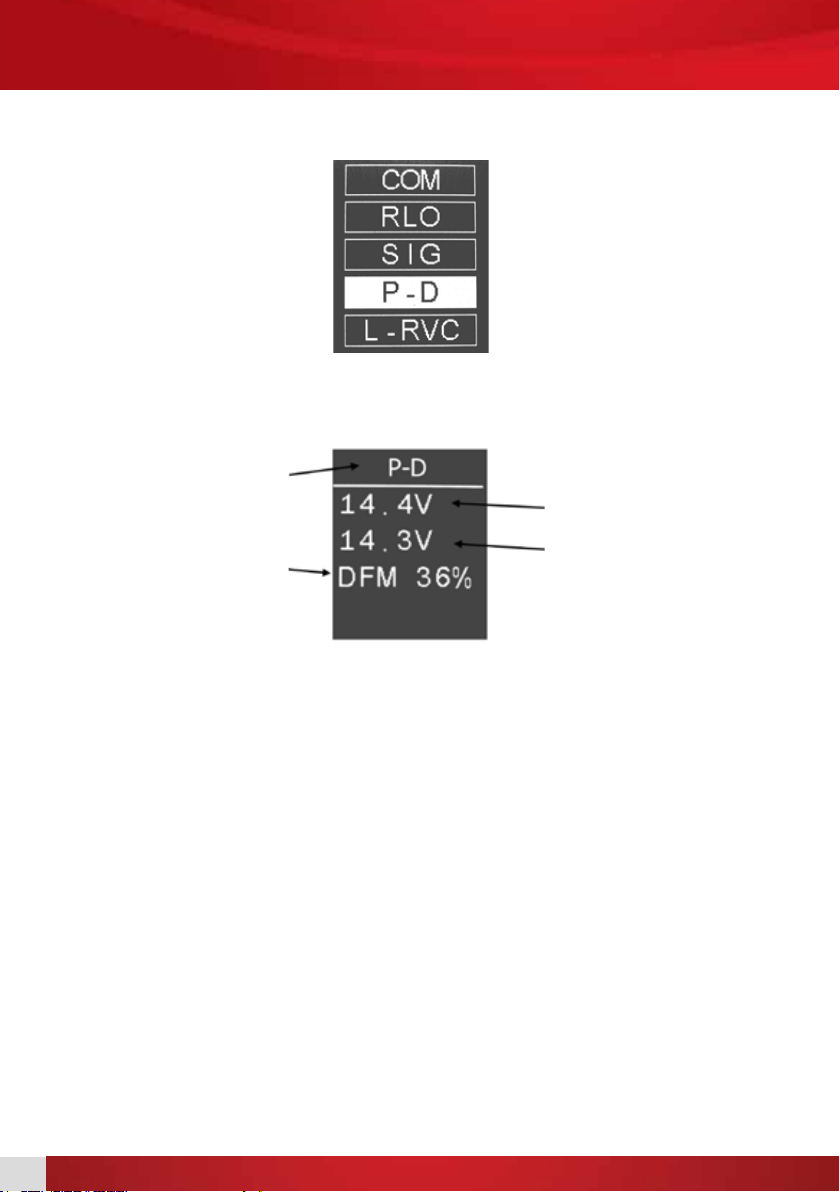
After connecting the testing device, the main menu will appear on the display:
Select the P-D function and conrm by pressing the OK button.
During the test, after starting the alternator drive, the actual voltage value should correspond to the
required value. Some discrepancies between the voltage values are acceptable. What is important is the
appropriate reaction of the alternator – increasing or decreasing the output voltage according to the
required voltage.
Selected function
DFM value
Required voltage
Actual voltage

11
Mazda P-D Testing General Motors L-RVC Testing
General Motors L-RVC Testing
General Motors, Opel,Vauxhall
Alternator connection:
L(PCM) pin RC (Green)
F(RVC) pin M (Blue)
B+ connection B+ (Red)
Alternator bracket/casing B- (Black)
M
F(RVC) L(PCM)

12
After connecting the testing device, the main menu will appear on the display:
Select the L-RVC function and conrm by pressing the OK button. The device will go into the L-RVC
testing mode and display the following information:
During the test, after starting the alternator drive, the actual voltage value should correspond to the
required value and the DFM value should correspond to the current alternator load.
Some discrepancies between the voltage values are acceptable.What is important is the appropriate
reaction of the alternator – increasing or decreasing the output voltage according to the required
voltage.
General Motors L-RVC Testing
Selected function
DFM value
Required voltage
Actual voltage
13
Toyota RLO Testing
Toyota RLO Testing
Toyota
M
IG RLO
L
Alternator connection:
IG pin Existing IG connection.
RLO pin RC (Green)
L pin Existing L (Control Lamp) connection.
M pin (DFM) M (Blue)
B+ connection B+ (Red)
Alternator bracket/casing B- (Black)
The connection of the L and IG pins are implemented independently of the AD100+, by using the
connectors located in the vehicle or on the testbench.
General Motors L-RVC Testing

14
Toyota RLO Testing i-STARS Testing
After connecting the testing device, the main menu will appear on the display:
Select the RLO function and conrm by pressing the OK button. The device will go into the RLO testing
mode and display the following information:
During the test, after starting the alternator drive, the actual voltage value should correspond to the
required value and the DFM value should correspond to the current alternator load.
Some discrepancies between the voltage values are acceptable.What is important is the appropriate
reaction of the alternator – increasing or decreasing the output voltage according to the required
voltage.
Selected function
DFM value
Required voltage
Actual voltage

15
Toyota RLO Testing i-STARS Testing
i-STARS Testing
PSA
B+ D D LIN GND
i-STARS connections:
Plug:
B+ connection Existing alternator battery positive.
LIN pin RC (Green)
GND pin Existing alternator ground.
Power cables:
B+ connection B+ (Red)
Alternator bracket/casing B- (Black)
The M (Blue) is left disconnected when testing.
The connection of the B+ and GND pins are implemented independently of the AD100+, by using the
connectors located in the vehicle or on the testbench.

16
i-STARS Testing
Select the COM function from the main menu and conrm by pressing the OK button.
The device will go into the COM testing mode and display the following information:
During the test, after starting the alternator drive, the actual voltage value should correspond to the
required value and the DFM value should correspond to the current alternator load. Some discrepancies
between the voltage values are acceptable. What is important is the appropriate reaction of the
alternator – increasing or decreasing the output voltage according to the required voltage.
Selected function
DFM value
Additional information
Required voltage
Actual voltage

17
i-STARS Testing Frequently Asked Questions
Can the device be damaged due to improper connection?
The device is resistant to connection errors from typical applications and voltage ranges.
Can the device damage connected units?
The device cannot directly damage any connected units, however the range of voltage sent to the
alternator is very broad and includes prohibited values (over 15V), which can result in electrical system
errors if the alternator is tested without removing it from the vehicle.
Can the device or connected units be damaged by selecting an improper testing function?
The only consequence of selecting an improper testing mode is the lack of a response from the
connected alternator.
Does the blue M connector have to be connected at all times?
Some alternators with a COM interface do not have an analogue DFM output. In this case, the M wire is
left unconnected.
Is it possible to use longer wires to connect units?
The device works with wires up to 5 metres long.
Can the testing device be used for 24V systems?
Yes.
After connecting the device, the display does not illuminate, show the start screen, or the
main menu – what should I do?
In this case, check if the testing device is properly connected, if the voltage of the connected system is
correct, and if yes, check the continuity of the connection wires.
How to store the testing device?
The device is best stored in a warm, dry place.
How to remove stains from the enclosure?
The device should be protected against exposure to any liquids or other substances that can penetrate
the enclosure. Stains are to be removed with a soft, moist cloth and a mild detergent. Do not use
naphtha, paint thinners, or solvents as they may lead to fogging of the display and damaging the coating.
Can the testing device be mounted on a testing table?
Yes, if it can be done without damaging the device’s enclosure. Do not drill any holes or put any screws
through the enclosure.
Why does the device display an error in the COM mode when the alternator stops
revolving?
Digitally controlled voltage regulators generate error information, displayed on the testing device, upon
detecting parameters outside the allowable range. In the case of alternator stoppage, this is a simply
a lack of revolutions error which should disappear once the rotor starts spinning again.This type of
behaviour is standard and conrms the alternator is working properly.

18
Why does an alternator with a COM interface start working only after I change the
required voltage for the rst time?
This is due to the alternator voltage regulator function. This type of behaviour is standard and conrms
the alternator is working properly.
Can the testing device be used to test alternators with a F1 – F2 connector?
Such alternators work with an external voltage regulator and require a different testing methodology.
Frequently Asked Questions

19
Software UpdateFrequently Asked Questions
The AD100+ is equipped with NFC (Near Field Communication) that enables wireless software updates.
Updates are safe and the device always holds both the new and last version of the software for easy
rollback.
Device Serial Number
Every AD100+ device has a unique serial number. This number is required to get update information and
to purchase new software updates. Please record your AD100+ serial number and store in a safe place.
To view the AD100+ serial number:
1. Power up the device.
2. While in the main menu press the button together with the OK button. [1]
3. Keep them pressed until the update menu appears on the screen. [2]
You will then be able to read your serial number and your current software version.
Software Update Requirements
12V power source (e.g. vehicle battery, bench power supply).
Android mobile phone with NFC, Internet WiFi, and installed AD100+ updater app.
[1] [2]
Table of contents
Other AUTODIAGGER Test Equipment manuals


Popular Test Equipment manuals by other brands


Optoelectronics
Optoelectronics Scout user manual

Nagas
Nagas ABE Series Installation, operation and maintenance manual

Tradinco
Tradinco TRAQC-2 PCHP user manual

Chauvin Arnoux
Chauvin Arnoux C.A 6115N user manual

Hioki
Hioki MEMORY HiCORDER 8855 instruction manual

Fluke
Fluke FiberInspector Pro FI-7000 Getting started guide