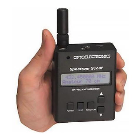
Optoelectronics Scout User manual

160 West Camino Real #233
Boca Raton, FL 33432
Telephone: 954-642-8997
Fax: 954-636-3533
Email: [email protected]
nternet: www.optoelectronics.com
®
OPTOELECTRONICS

Scout
USER MANUAL

Table of Contents
ntroduction 1
Quick Start Guide 2 -4
External Connections 5
Front Panel Controls 6-8
Front Panel Display and ndicators 9 - 10
Communications Language 11
Specifications 12
Operation 13 - 20
Reaction Tuning 16 - 17
Antenna and Accessory Recommendations 21
Factory Service 22 - 23

24
The Optoelectronics logo is a registered trademark of Optoelectronics, nc.
© Copyright 2008 Optoelectronics, nc.
160 West Camino Real #233
Boca Raton, FL 33432 U.S. atent No.
5,471,402

Factory Service
RETURN OLICY
The Optoelectronics Service Department will provide rapid turnaround of your repair. No return
authorization is required. Enclose complete information as follows:
1. Copy of sales receipt if under warranty.
2. Detailed description of problem(s).
3. Complete return address and phone number (UPS street address for USA).
4. Proper packaging (insurance recommended). Note: Carriers will not pay for
damage if items are improperly packaged.
5. Proper remittance including return shipping, if applicable (Visa/MasterCard
number with expiration date, Money order, Company PO, etc.). Note:
Personal checks are held for a minimum of two weeks before shipment.
Address all items to: Optoelectronics, nc.
Service Department
160 West Camino Real #233
Boca Raton, FL 33432
f in question, contact the factory for assistance. Service Department: (954) 642-8997. Monday -
Friday 8:30 AM to 5:00 PM Eastern Time.
23

This manual covers connection and operating instructions for the
Optoelectronics ScoutTM. The Optoelectronics ScoutTM is covered under
U.S. atent Number 5,471,402
C
C
WARNING - Maximum input voltage is 12VDC. Automotive voltages may exceed 12V caus-
ing damage to internal circuitry. Damage resulting from excessive input voltage is readily
apparent and will not be covered under warranty. Units returned for warranty service that have
damage resulting from excessive supply voltages will incur service charges.
WARNING - Maximum antenna input signal is +15dBm (50mW). Under no circumstances
should the Scout be directly connected to an RF transmitter or be used in close proximity to a
radio transmitter of more than 5 watts. Damage to the input amplifier circuitry is readily appar-
ent and will not be covered under warranty. Units returned for warranty service that have dam-
age to the input circuitry will incur service charges.
CAUTION
!

ntroduction
1
The Scout is the latest advancement in hand-held frequency test instruments. t excels at finding and
recording frequencies for security, law enforcement, commercial and recreational applications. Patented
technology developed by Optoelectronics employs statistical analysis to filter out actual radio transmis-
sion frequencies from the background RF.
The Scout is more than a test instrument in the traditional sense because it is useful for finding frequen-
cies being used for two way radio communications. Designed to work with an antenna to pick up trans-
mitted radio frequencies, it is actually a frequency recorder. Up to 400 unique frequencies can be stored
in memory, along with up to 255 hits on each frequency.
The counter circuitry produces a coherent and stable count when there is a single dominant signal 10 to
20 dB stronger than any other signal or the RF floor. An embedded microprocessor evaluates each mea-
surement statistically to determine when an actual RF frequency is dominant. This is the digital filter pro-
cessing which makes automatic capture and recording possible.
Features include a signal strength bargraph, audible beeper, vibrator, internal NiCad batteries, and single
range operation. The Scout includes an AC-90 power adapter.

Factory Service
22
RODUCT WARRANTY
Optoelectronics, nc. warrants all products and accessories for one (1) year against defects in materi-
als and workmanship to the original purchaser. Products returned for warranty service will be
repaired or replaced at Optoelectronics’ option.
Specifically excluded are any products returned under this warranty that upon examination, have
been modified, had unauthorized repairs attempted, have suffered damage to the input circuitry from
the application of an excessive input signal, have suffered damage to the charging circuitry or inter-
nal batteries from the application of excessive voltage, or show other evidence of misuse or abuse.
Optoelectronics reserves sole right to make this determination.
No other warranties are expressed or implied, including but not limited to the implied warranties of
merchantability and fitness for a particular purpose. Optoelectronics, nc. is not liable for consequen-
tial damages.
WARRANTY
Products under warranty must be returned, transportation prepaid, to Optoelectronics’ service center.
All parts replaced and labor performed under warranty are at no charge to the customer.
NON-WARRANTY
Products not under warranty must be returned, transportation prepaid, to Optoelectronics’ service
center. Factory service will be performed on a time and materials basis at the service rate in effect at
the time of repair. A repair estimate prior to commencement of service may be requested. Return
shipping will be added to the service invoice and is to be paid by the customer.

Antenna and Accessory Recommendations
ANTENNAS
The small dual band, VHF/UHF, DB32 antenna is a very good multi-purpose antenna capable of pick-
ing up a very wide range of frequencies from 100MHz to 1GHz. There are other antennas available that
are useful for specific frequency ranges.
RD27 26-150MHz
RD150 144-165MHz
RD440 440-480MHz
RD800 500MHz-1GHz
BB85 100MHz-2GHz
DB32 100MHz-2GHz
Cell Lock824MHz-2GHz
TA100S 100-600MHz.
FILTERS
The N100 FM broadcast notch filter will remove the influence from local FM stations.
SERIAL DATA INTERFACE
n order to download the memories of the Scout, the Optoelectronics Optolinx serial data interface is
needed. The Optolinx universal PC interface adapts for use with a wide variety of receivers, frequency
counters and frequency recorders for the purpose of computer control of a receiver and downloading
memories of the Scout. The Optolinx comes supplied with the CB-C 5 cable, which is necessary in order
to interface the Scout to the Optolinx for downloading.
21

Quick Start Guide
Step 1 TURN THE SCOUT ON
Set the POWER switch to the on position. On power-up, an LCD self-test will be displayed for two
seconds, followed by the COMMUN CAT ONS LANGUAGE for two seconds.
f the CAPTURE switch is ON when the Scout is turned on, the beeper is enabled.
Step 2 SELECT COMMUNICATIONS LANGUAGE
There are two different communications settings for the Scout; C -5 and AR8000.
To change the communications language:
1. Make sure F LTER and CAPTURE switches are in the ON position, or up.
2. Just after switching the power on, slide the CAPTURE switch to the OFF position, or down.
3. The Scout will display the new communications language.
Step 3 SELECT NORMAL MODE
NORMAL mode is selected by placing both the F LTER and CAPTURE switches in the OFF posi-
tion. n this mode the Scout functions as a conventional free-running frequency counter, where fre-
quency measurements are continuously displayed. The gate setting can be changed by pressing the
GATE/RECALL/CLEAR push-button switch on the front panel. The Scout has four different gate
settings.
2

Quick Start Guide
3
Step 4 SELECT FILTER MODE
F LTER mode is selected when the F LTER switch is ON and the CAPTURE switch if OFF.
Frequencies are locked on the display but not logged to memory. The gate setting can be changed by
pressing the GATE/RECALL/CLEAR push-button switch on the front panel.
Step 5 SELECT CA TURE MODE
CAPTURE mode is selected when the F LTER and CAPTURE switches are both ON. n this mode,
frequencies captured are displayed and stored into memory, along with the number of hits of each fre-
quency. n CAPTURE mode, the 1KHz resolution gate time is always selected.
Step 6 REACTION TUNING
REACT ON TUN NG is selected when the Scout is in either F LTER mode or CAPTURE mode. When
interfaced to a compatible receiver the Scout will automatically tune the compatible device to the fre-
quency it captures. Please refer to page 16 & 17 of this manual for detailed instructions on how to set
up each compatible device for REACT ON TUN NG.
Step 7 SELECT RECALL MODE
RECALL mode is selected when the F LTER switch is OFF and the CAPTURE switch is ON. n this
mode the operator can view all 400 frequencies and all 255 hits in memory. Memories are displayed
as four banks of 100 memories. The “A” and “B” annunciators are used to indicate which bank is
currently being displayed.
Solid “A” indicates memories 0-99
Solid “B” indicates memories 100-199
Flashing “A” indicates memories 200-299
Flashing “B” indicates memories 300-399

Operation
20
Charging the Scout will take approximately 8-10 hours using the AC-90 adapter. t is normal for the
Scout to become warm when charging is taking place. Make sure the ambient temperature is not
excessive and that there is sufficient air flow to help cool the unit.

Operation
MEMORY TUNING
When RECALL mode is selected, the Scout automatically tunes a connected receiver to the frequen-
cy stored in the currently displayed memory location. Each time the displayed memory location is
changed by pressing the GATE switch, a corresponding tuning command is transmitted to the receiv-
er. This feature allows the user to instantly tune to transmissions on frequencies which have been
previously captured by the Scout.
MEMORY CLEAR
Because memory data is protected from all but catastrophic power loss, it is necessary to manually
clear the memory when it is full. Memory clear is accomplished by holding down the
GATE/RECALL/CLEAR push-button switch while turning the power switch off. f the Scout mem-
ory is cleared, all captured frequencies and hits stored in memory are lost. To keep a permanent
record of the frequencies and hits stored in memory, be sure to select NORMAL mode and download
them to a personal computer using the Optolinx (optional) computer interface.
CHARGE O ERATION
1. The Scout will automatically shut down when the battery pack is discharged.
2. f the battery pack is permitted to completely discharge, charging may terminate after only a few
minutes. This is a safety feature to protect the battery pack, theScout and the user. f this happens,
charging can be restarted by re-applying power (unplug the power adapter and plug it back in).
3. f the battery is not recharged and is permitted to discharge even further, the charge circuit must be
restarted several times before a complete charge will occur.
19

Quick Reference Guide
4
NO ANNUNCIATOR
BEEPER
Just after switching the power on,
slide the CAPTURE switch to the
OFF position to change the commu-
nications mode.
POWER UP MODES
(Unit is being turned on)
OPERATION
Communic-
ation
Mode
NOR AL
COUNTER
ODE
FILTER
ODE
CAPTURE
ODE
RECALL
ODE
Push Button To
Change Gate
Time
Push Button To
Change Gate
Time
Push Button To
Scroll emories
and hits
Hold Button To
Clear emory
While Turning
Power Off
HOW TO
READ
E ORIES
LCD DISPLAY
00-99 A-SOLID 0-99
00-99 B-SOLID 100-199
00-99 A-FLASHING 200-299
00-99 B-FLASHING 300-399
VIBRATOR Hold button
down while
powering on

External Connections
5
The Scout has four external connections located on the top panel. The functions of each are briefly
described below.
OWER
DC power is supplied to the Scout through the POWER connector, a standard 5.5 mm o/d., 2.1 mm i/d.
coaxial DC power jack located on the top panel (9-12 VDC, 500-1200mA max, center positive). The
POWER input is used for operation of the Scout from an external power source (AC-90 supplied), as
well as for charging the internal NiCad battery.
RF IN UT
The RF NPUT connector is a BNC connector located on the top panel, which provides a 50 Ohm RF
input to the Scout. This input is intended for antenna input use.
CI-V
The C -V connector is a subminiature (2.5 mm) phone jack used to connect the Scout to a computer for
the purpose of downloading stored frequency information. The connector is also used to connect the
Scout to a receiver for the purpose of Reaction Tuning. Receivers capable of interfacing to the Scout
for the purpose of Reaction Tuning are: COM R10, R7000, R7100, R8500, R9000, and the AOR
AR8000/AR8200. Also, the Radio Shack PRO 2005/2006 (with OS456/Lite installed) and PRO-2035/
2042 (with OS535 installed), Optoelectronics R11 and OptoCom Receiver. The serial interface con-
forms to the COM C -V interface standard. The T P carries the TTL serial data, and the SH ELD pro-
vides the return.

Operation
18
RECALL MODE
Recall mode is selected by placing the F LTER switch in the OFF position and the CAPTURE switch
in the ON position. RECALL mode is indicated by the “RECALL” annunciator on the front panel dis-
play. n this mode the operator can view all 400 frequencies and counts stored in memory. No fre-
quency measurements can be made when RECALL mode is selected. However, the RF signal strength
bargraph continues to function as before. As in CAPTURE mode, memories are displayed as four banks
of 100 memories using the “A” and “B” annunciators to indicate which bank is currently being dis-
played. Solid “A” indicates memories 0-99, solid “B” indicates memories 100-199, flashing “A” indi-
cates memories 200-299, and flashing “B” indicates memories 300-399. When RECALL mode is first
selected, the frequency stored in memory location 00 is displayed on the LCD. Pressing the
GATE/RECALL/CLEAR push-button switch causes the number of hits for memory location 00 to be
displayed. Pressing the push-button a second time causes the frequency stored in memory location 01
to be displayed. Pressing the push-button a third time causes the number of hits for memory location
01 to be displayed. After memory location 399 is displayed, the sequence starts again at memory loca-
tion 00. To scroll rapidly through the 400 memory locations, simply press and hold the push-button
switch. Switching back to CAPTURE mode will cause the Scout to resume capturing frequencies, but
the frequencies already stored in memory will be preserved. New occurrences of previously captured
frequencies will continue to increment the frequency count as before. New activity will only add to the
existing data, not replace it.

Operation (Reaction Tune)
17
4. Make sure the receiver is powered on before the Scout. Then turn the Scout on so that the initial-
ization command may be sent to the receiver.
5. Key up any radio and the Scout will automatically tune the receiver to the frequency of the radio.
AR8000
1. Upon powering the Scout on the LCD will display the words Scout followed by the current com-
munications language. Confirm that the Scout displays AR8000. f the current setting is not the
desired setting refer to the COMMUN CAT ONS LANGUAGE section of this manual for infor-
mation on how to change to the desired setting.
2. Attach the flat flexible end of the SAC 8000 cable (optional) to the serial port underneath the bat-
tery compartment of the AR8000. Attach the 2.5mm portion of the cable to the C -V jack located
on top of the Scout.
3. Make sure the AR8000 is powered on before the Scout. Then turn the Scout on so that the initial-
ization command may be sent to the AR8000.
4. Key up any radio and the Scout will automatically tune the AR8000 to the frequency of the
radio.
5. The Scout will also tune the AR8200 with an optional cable.

Front Panel Controls
6
The Scout has four front panel controls. The functions of each are briefly described below. A
more detailed discussion of the functions of the front panel controls is given in the OPERAT ON
section.
OWER
The POWER switch activates the Scout. When the POWER switch is in the ON position, the
Scout is powered from the internal NiCad battery pack. f external power is present then a trick-
le charge cycle can occur. When the POWER switch is in the OFF position and the Scout is pow-
ered from an external power source, the battery pack will charge automatically.
FILTER
The F LTER switch, in conjunction with the CAPTURE switch, is used to select the operating
mode of the Scout. When the F LTER and CAPTURE switches are both in the OFF position,
NORMAL mode is selected, and the Scout functions as a conventional frequency counter. When
the F LTER switch is in the ON position and the CAPTURE switch is in the OFF position, F L-
TER mode is selected. When the F LTER and CAPTURE switches are both in the ON position,
CAPTURE mode is selected. When the F LTER switch is in the OFF position and the CAPTURE
switch is in the ON position, RECALL mode is selected.

Front Panel Controls
7
CA TURE
The CAPTURE switch, in conjunction with the F LTER switch, is used to select the operating mode of
the Scout as described above. When the F LTER and CAPTURE switches are both in the ON position
then CAPTURE mode is selected. The CAPTURE switch also has two alternative functions. When the
Scout is turned on with the CAPTURE switch in the ON position the beeper is enabled. Turning the
Scout on with the CAPTURE switch in the OFF position disables the beeper.
GATE/RECALL/CLEAR
The GATE/RECALL/CLEAR push-button switch has three main functions. When the Scout is in NOR-
MAL mode or F LTER mode, the push-button switch changes the gate time, and hence the measure-
ment resolution. The Scout has four gate settings. Each time the push-button switch is pressed, the next
gate setting is selected. The currently selected gate setting is indicated by the position of the decimal
point on the frequency display. The gate time, measurement time, and measurement resolution corre-
sponding to each gate setting are summarized in Table 1.
When the Scout is in CAPTURE mode, the 1 KHz resolution gate setting is automatically selected.
When the Scout is in RECALL mode, the push-button switch changes the frequency memory location
displayed on the front panel display. The Scout can store up to 400 frequencies along with the number
of occurrences of each frequency. Each time the push-button switch is pressed, the next memory loca-
tion frequency or count is displayed. When the Scout is in RECALL mode the 1KHz resolution gate
setting is automatically selected.

Operation (Reaction Tune)
16
REACTION TUNE
When the Scout is in F LTER mode or CAPTURE mode it can Reaction Tune a receiver connected to the
serial interface of the Scout. Following are the procedures for Reaction Tuning the various receivers that
are compatible with the Scout.
CI-5
1. Upon powering the Scout on, the LCD will display the words Scout followed by the current communi-
cations language. Confirm that the Scout displays C -5. f the current setting is not the desired
setting refer to the COMMUN CAT ONS LANGUAGE section of this manual for information on
how to change to the desired setting.
2. Following are the current C -5 compatible receivers that the Scout is capable of Reaction Tuning.
COM R10, R7000, R7100, R8500 and R9000. Also, the Radio Shack PRO 2005/2006
(with OS456/Lite installed), Radio Shack PRO 2035/2042 (with OS535 installed) and the
Optoelectronics R11 and OptoCom.
The COM R10 and R7100 require special default settings for Reaction Tuning with the Scout.
COM R10: Baud Rate = 9600, TRN = ON, C -V ADDRESS = 52
COM R7100: Baud Rate = 9600, Transceive Mode = ON
3. Attach the 3.5mm portion of the CB-C 5 cable (optional) into the Radio Remote jack on the (R7000,
R7100 and R9000) and the C -V jack on the R10 and Radio Shack models. Attach the 2.5mm portion
of the cable into the C -V jack located on top of the Scout.
Other manuals for Scout
1
Table of contents
Other Optoelectronics Test Equipment manuals