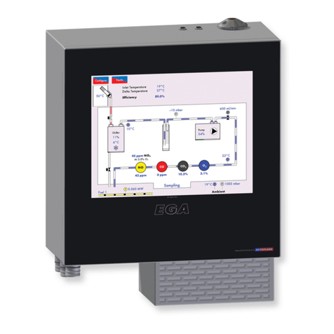
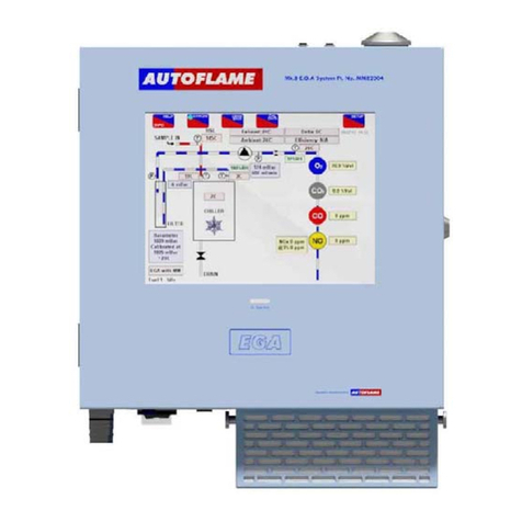
AUTOFLAME MK8 EGA EVO Manual

M
d
A
m
t
Mk8
an
E.G.A.
Se
t
-
Up
Trim
Gui
d
e
Mk8
尾气
分析仪设置
和调节指南


Mk8
E.G.A. Set-Up
and
Trim
Guide
Mk8 尾气分析仪设置和调节指南
Issued
by 发布公司:
AUTOFLAME
ENGINEERING
LTD
AUTOFLAME 工程有限公司
Unit 1-2,
Concorde Business
C
entre
Airport Industrial
Estate,
WirelessRoad
Biggin
Hill, Kent TN16
3YN
Tel:
+44 (0)845 872
2000
电话:
+44 (0)845 872
2000
Fax: +44 (0)845 872
2010
传真:+44 (0)845 872
2010
Email: [email protected]
电子邮件:
Website:
http://www.autoflame.com/
网站:
http://www.autoflame.com/
Registered
Holder 注册持有人:
Company 公司:
Department 部门:
This
manual and all the information
contained
herein
is copyright
of
Autoflame
Engineering Ltd.
It may not be
copied
in the whole or part without
the
consent
of the Managing
Director.
Autoflame工程有限公司拥有本手册的所有版权。在未经Autoflame公司常务董事同意的情况
下,本手册内容不得被整体或部分引用。
Autoflame
Engineering Ltd’s policy is
one of
continuous
improvement in
both
design
and manufacture. We therefore reserve the right to
a
m
end
specifications
and/or data without prior
notice.
All details
contained
in
this
manual are
correct
at the time of going to print.
Autoflame工程有限公司致力于不断提升Autoflame产品的设计和制造,我们保留修订本手册
规范/数据的权利,恕不另行通知。本手册内容于付印时准确无误。

Important
Notes
重要说明
A knowledge of
combustion
related
procedures
and
commissioning is essential
before
embarking work on any of the M.M./E.G.A.
systems. This
is for safety reasons and
effective
use
of the
M.M./
E.G.A. system.
Hands on training
is
required. For details on
schedules
and
fees
relating to group training
courses
and individual
instruction,
please
contact
the Autoflame
Engineering Ltd. offices
at the
address listed
on the front.
为了安全有效地使用控制模块/EGA 系统,控制模块/EGA 系统的操作员必须具有与燃烧相关的流程
知识和调试知识。我们要求操作员参加实践培训,请按首页所述地址联系上 Autoflame 办公室详细
了解团体培训课程和个别辅导的时间和费用。
Short Form -
General
Terms
and
Conditions
一般条款
A full statement of our
business terms
and
conditions
are printed on the reverse of
all
invoices.
A copyof
these can
be
issued
upon application, if requested in
writing.
所有发票背面均都印有我方商业条款全文。客户可书面申请获取我公司的商业条款文件。
The
System
equipment
and
control
concepts
referred to
in
this
Manual
MUST
beinstalled,
commissioned
and applied by
personnel skilled
in the various
technical disciplines
that
are inherent to the Autoflame
product
range, i.e.
combustion, electrical
and control.
仅有专业人员才能安装、调试、使用本手册所提及的系统设备和控制原理。他们必须精通 Autoflame
产品所涉及的燃烧、电气和控制等技术学科。
The
sale of Autoflame’s
systems
and equipment referred to in
this
Manual
assume
that
the dealer,
purchaser
and installer has the
necessary skills
at
his disposal.
i.e. A high
degree of
combustion
engineering experience, and a thorough understanding of the
local electri
c
al
codes
of
practice concerning boilers, burners
and their ancillary systems
and equipment.
经销商、采购商和安装人员必须具有丰富的燃烧工程从业经验、全面了解当地涉及锅炉、燃烧器和辅
助系统/设备相关的电气行业规范方能使用本手册提及的 Autoflame 系统和设备。
Autoflame’s warranty from point of sale is two years on all
electronic systems
and
components.
Autoflame 保修条款: 对所有电子系统和部件实行两年售后保修。
One year on all
mechanical systems, components
and sensors.
对所有机械系统、部件和传感器实行一年售后保修。
The
warranty
assumes
that all equipment supplied will be used for the purpose that
it was intended and in
strict compliance
with our
technical
recommendations.
Auto
-
flame’s warranty and guarantee
is
limited
strictly
to
product
build quality, and design.
Excluded
absolutely are any
claims
arising from
misapplication, incorrect
installation
and/or
incorrect
commissioning.
保修前提: 所有设备均按预期使用目的使用并严格遵守我方提供的的技术建议。Autoflame 产品保修
条款仅适用于产品制造质量问题和设计问题。根据保修条款,Autoflame 不接受因误操作、误安装和/
或调试导致的任何索赔请求。

Contents 目录
1
INTRODUCTION
前言
.................................................................................. 1
1.1
Overview and
Benefi
ts
.
概述与优点
.. ........................................................................
1
1.1.1
Features and
Benefits
.
特点与优点
. .......................................................................
1
1.1.2
System
Operation
系统运行
..........................................................................
1
1.1.3 Mk8
E.G.A. vs
Mk7
E.G.A.
Mk8 和Mk7 尾气分析仪
......................................................
2
1.2
3-Parameter Trim
3参数调节
..... ................................................................................................
2
1.3 Continuous Emissions
Monitoring
System
持续排放检测系统
.... ...............................................
3
2 WIRING AND
CO
MP
ONENTS
.
接线和主件
....................... ...... ...... ............... 4
2.1
Flying Lead Wiring
Diagram
.
飞线接线图
.............................................
4
2.2
Electrical
S
c
he
matics
.
电气原理图
............................................. ................................................
6
2.2.1
Interconnection between E.G.A. and
Mk7
M.M.
...........................................................
6
尾气分析仪和 Mk7 控制模块的互连
2.2.2
Interconnection between E.G.A. and
Mini Mk8 M.M.
Module
....... .................................
7
尾气分析仪和 Mk8 微型控制模块的互连
2.2.3
Interconnection between Stand-Alone
Mk8
E.G.A. and
Mk7
D.T.I.
............
8
单机 Mk8 尾气分析仪和 Mk7OTI 的互连
2.2.4
Interconnection between
Mk7 M.M., Mk8
E.G.A. and
Mk7
D.T.I.
.......................
9
Mk7 控制模块、Mk8 尾气分析仪和 Mk7 数据传输接口的互连
2.3
Components
组件
......... ....................................................................................
10
2.3.1
Inside View
内视图
. .......................................................................................
10
2.3.2
E.G.A. Connections.
尾气分析仪的连接
...............................................................
11
2.4
Cell Characteristics
感应器特点
.. ......................................................................
12
2.4.1 O2
Cell..
O2感应器
............................................... ........ ........ ........ ........ ......................
12
2.4.2
CO,
NO, NO2
and
SO2
Cells
.
CO,
NO, NO2
和
SO2感应器
...... ....................................
13
2.4.3
CO2
Sens
or
..
CO
2
传感器
......... ............................................. .........................................
13
3.
SET-
UP
..
设置
.
..................................................................................................14
3.1
E.G.A. Set-Up
尾气分析仪的设置
.........................................................................................
14
3.1.1
Sampling Screen
采样屏幕
............................................................................................
14
3.1.2 Mk8
E.G.A. Settings
.
Mk8 尾气分析仪的设置
...................................................
16
3.1.3
Cell Status
S
c
r
een
.
感应器状态屏幕
.................................................................
17
3.1.4
Fault
History
故障历史
.....................................................................................................
18
3.1.5
Factory Settings Screen
..
出厂设置屏幕
................................................
20
3.1.6
4-20mA
Set-u
p
.
4-20mA
设置
............................................................
21
3.1.7
Operating Mode Set-up.
运行模式设置
..............................................................
22
3.1.8
Time
and Date .
时间和日期
..............................................................
23
3.1.9
Change
Password
.
更改密码
..... ....................................................................................
24

3.2
CEMS Set-Up
CEMS 设置
........ .............................................................................
25
3.2.1
Fuel
Selection.
燃料选择
......... .........................................................................
25
3.2.2
Fuel
Flow Source
燃料流量源
....... ..............................................................................
27
3.2.3
Unit Measurement
设备测量
......... ............................................................................
28
3.3
CEMS
Data Screens..
CEMS
数据屏幕
....... ............................................................................
29
3.4
CEMS
Energy Audits .
CEMS 能源检查
............. ...................................................................
33
3.5
Trim
Settings..
调节设置
................ .............................................................................
35
3.5.1
Relevant
Mk7 M.M.
Opti
on
s
............ ....................................................................
35
Mk7 控制模块相关选项
3.5.2
Relevant
Mk7 M.M.
Parame
ters
......... ......................................................................
38
Mk7 控制模块相关参数
3.5.3
Relevant
Mini Mk8 M.M.
Op
tions
......... ..........................................................................
41
Mk8 微型控制模块相关选项
3.5.4
Relevant
Mini Mk8 M.M.
Parameters...... ....................................................................
44
Mk8 微型控制模块相关参数
3.5.5
Commissioning
Procedure.
调试流程
.... .........................................................................
46
3.6 Mk8
E.G.A.
T
r
im
........... ..................................................................................
47
Mk8 尾气分析仪的调节
3.6.1
Trim
Operation
调节操作
........ ..............................................................................
47
3.6.2
Quick Commission
Mk7
M.M.
... .............................................................................
49
快速调试 Mk7 控制模块
3.6.3
Quick Commission
Mini Mk8
M.M.
... ......................................................................
50
快速调试 Mk8 微型控制模块
3.6.4
Trim Timing
Operation .... ............................................................................
51
调节定时操作
3.6.5
Graphical Trim
Operation .. ...................................................................................
52
图形调节操作
3.6.6
Channel
5
Trim
....... ...................................................................................
53
通道 5的调节
3.6.7
Combustion Efficiency Calculations
.... ................................................................
53
燃烧效率的计算
3.7
Combustion
Limits
燃烧限值
................... .....................................................................................54
3.7.1
Overview
of
Combustion Limits
燃烧限值概述
...............................................................
54
3.7.2
Standard
Limits
标准限值
........... ........................................................................
54
3.7.3
Absolute
Lim
i
t
s
.
绝对限值
........ .....................................................................
54
3.7.4
Combustion Limits Control
F
uncti
on
s
..... .............................................................
54
燃烧限值控制功能
3.7.5 O2
Limits Example
氧气限值示例
....... ......................................................................
55
3.7.6 NO
Limits
Exam
ple
...... .....................................................................
56
一氧化氮限值示例
3.7.7
CO L i m i t
Exa
m
p l e
.......................................
57
一氧化碳限值示例

3.7.8
Temperature Limits
Exam
p
l
e
温度限值示例
....... .............................................................
58
3 DIMENSIONS AND
EQUIPMEN
T
尺寸和设备
.. .................... 59
4.1 Mk8
E.G.A. Dimensions.. ..................................................................
59
Mk8 尾气分析仪尺寸
4.2
Technical Specifications
技术规范
......... .................................................................
60
4.3
Sampling Probe
采样探头
............. ................................................................
61
4.3.1
Installation and Maintenance .
安装和维护
.. ................................................................
61
4.3.2
Sampling Probe Assembly
.
采样探头总成
.... .................................................................
62
4.3.3
Sampling Probe Internal Filter
...... ...............................................................
63
采样探头内部过滤器
4.3.4
Sampling Probe Maintenance . ................................................................
64
采样探头的维护
4.3.5
Servicing E.G.A. Sampling Probe
. .............................................................
64
尾气分析仪采样探头的维护
4.4
Ancillary Equipment.
辅助设备
...... ...........................................................
65
4.4.1
External Particulate
F
ilter
.
外部微粒过滤器
......... ..........................................................
65
4.4.2 Air
Inlet Filter
.
进气过滤器
.............................................................................................
66
4.4.3
Chilled Environmental
Encl
o
s
ure.
冷却环境保护罩
..................................... ...................
67
4.4.4
Pre-Heat
Air
Sensor
预热空气传感器
................ ................ ................ ...........................
68
5.
ERROR CHECKING
AND
SELF-DIAGNOSTICS
错误检查和自诊断
......................... 69
5.1
E.G.A.
Faul
ts
.
尾气分析仪故障
.............................................................................................
69
5.2
Troubles
hoo
t
i
n
g
故障排除
.......................................................................................................
70
5.2.1
Ambient Conditions
环境条件
............. .......................................................................
70
5.2.2
Fuses
保险丝
....................................... .......................................................................
70
5.2.3 O2
Reading .
氧气读数
...................... .........................................................................
70
5.3 Mk8
E.G.A. Faults
Mk8 尾气分析仪故障
........ .............................................
71
5.3.1
Trim
Delay
调节延迟
......................... ........................................................
73
5.3.2
Assembly
of
Dry Filter
干滤器的组装
........ .............................................................
73
5.4
E.G.A. Best
Pr
actice
............. ........................................................
74
尾气分析仪的最佳应用
5.4.1
Servicing the E.G.A.............. .............................................................
75
尾气分析仪的维护
5.4.2
Shipping the
E.G.
A.
......... ................................................................
75
尾气分析仪的运输
6
STANDARDS
标准
.........................................................................................
76


1
Introducti
on
前言
29.05.2015
Mk8
E.G.A. Set-Up and Trim
Guide Mk8 尾气分析仪设置和调节指南
Page
1
1
INTRODUCTION
前言
1.1 Overview and Benefits
概述与优点
1.1.1
Features
and
Bene
fits
特点与优点
The
Mk8
Exhaust
Gas Analyser (E.G.A.)
monitors
the
emissions
in the flue produced from the
burner/boiler
system. The
E.G.A. can improve
combustion,
increase efficiency, reduce fuel
consumption and improve safety through its
3
parameter trim function and combustionsafety
li
mits.
Mk8 尾气分析仪用于监视燃烧器和锅炉系统产生的烟道尾气。尾气分析仪能够改善燃烧、提高
效率、减少燃料消耗并通过 3参数调节功能和燃烧安全限制提高安全性。
1.
Stand-Alone: When
in
stand-alone mode, the E.G.A. can
be
used without
a
Micro-Modulation
(M.M.)
module
to
monitor the combustion gases. The
M.M.
trim function
and
the combust
i
on
safety limits
are not
activated
in
this stand-alone mode
of
operation. The emissions levels
can
be accessed via the full colour E.G.A. touch
screen.
单机运行:在单机模式下,尾气分析仪在无微型控制模块的情况下可以用于监视燃烧的
烟气。在单机运行模式下不会激活控制模块调节功能和燃烧安全限制。排放等级可以通
过全彩色尾气分析仪触摸屏访问。
2. With M.M.: When
interfaced
with an M.M., the E.G.A. can monitor
emissions
or the 3-
parameter combustion
trim and safety limits can be
activated. The emissions
levels are
monitored
by
the E.G.A.
and
the
M.M.
makes small adjustments
to
the
air
damper
to
trim
the
online exhaust gas data back
to
the commissioned values. The E.G.A. information is
accessible
through the
full
colour E.G.A. touch screen, the Data Transfer Interface module (D.T.I.),
or 6 x
4-20mA signals.
带控制模块:尾气分析仪在连接控制模块后可以监视排放,3参数燃烧调节功能和安全
限制可以被激活。排放等级可以通过尾气分析仪进行监视,控制模块对空气挡板进行微
调,使在线排气数据返回至调试的数据。尾气分析仪信息可以通过全彩色尾气分析仪触
摸屏、数据传输接口模块或 6 x4-20mA 信号进行访问。
The main benefits
of
the E.G.A. include the
ability to
monitor the exhaust gases
and bring
them
to the
safe commissioned levels. Setting
the
combustion limits
on the M.M. in
conjunction
with the E.G.A.
prevents unsafe combustion scenarios, reducing the fuel consumed
inbadcombustion.
尾气分析仪的主要优点包括监视排气并使其保持安全调试水平。在控制模块和尾气分析仪上设
置燃烧限值可以防止不安全的燃烧情况、减少在不良燃烧中的燃料消耗。
1.1.2
System
Operation
系统运行
The
Mk8
E.G.A. samples
the
combustion gases
via the
stack mounted sampling
probe
(p
urchased
separately
from the
analyser). The exhaust gases
are drawn from the
stack
by a pump
mounted
internally within the analyser.
Only
the supplied sample tubing should
be
used between the sampling
probe and
analyser. The internal diameter
of
the sampling tube is 3mm;
if a large
diameter tubing is
used the sample gas remains resident
in
the tubing
for a
longer period. The E.G.A.
will
then not be
able
to
respond
in
time
to
combustion changes, resulting
in
incorrect operation
of
the trim
function.
Mk8 尾气分析仪通过在排气管上安装的采样探头(需单独购买)对燃烧烟气进行采样。废气通

1
Introducti
on
前言
Page
2
Mk8
E.G.A. Set-Up and Trim
Guide Mk8 尾气分析仪设置和调节指南
29.05.2015
过安装在尾气分析仪内部的泵从排气管中抽出。在采样探头和尾气分析仪之间仅可使用提供的
采样管。采样管的内径为 3mm,如果使用大尺寸采样管,采样气体会在采样管中停留较长的
时间。这样尾气分析仪就无法及时对燃烧的变化做出响应,导致无法正确使用调节功能。
Once the exhaust gases have entered the E.G.A. the chiller block reduces their temperature and
drie
s
the
sample
to
remove
the
condensation
from the
gases
prior to
entering
the
cells. The condensate
accumulated
in
the chiller unit is drained every
4
minutes when running,
and
every
10
minutes
when
the E.G.A. is
in
idle mode, automatically through the drain
solenoid.
废气进入尾气分析仪后,冷却器组将降低其温度,在其进入设备前通过去除烟气中的冷凝水将
样本干燥。运行时在冷却器组中积累的冷凝水每隔 4分钟排出一次,当尾气分析仪处于空闲模
拟时每隔 10分钟排出一次,冷凝水将通过排放电磁阀自动排出。
The exhaust gas is then filtered through
the dry filter,
which
i
s
a fine filter
used
to
remove
any
d
u
s
t
particles carried over from the cooling process.
If
the burner is firing
on
heavy
or dirty oil, an external
particulate filter must
be
used
to
remove the excess
dirt
particles.
On
leaving the filter, the exhaust
gas
pressure is checked
again to
ensure
that a
vacuum is maintained
prior to
entering
the
pump
and on
exiting the pump, the pressure produced
by
the pump is checked. Both these pressure sensors
modulate
the
flow
rate
of
the sample into the E.G.A.
for
consistent operation. Once the exhaust gases have
been
conditioned, they
are
ready
for an
accurate sampling
by
the cells. After the gases have been sampled
by all
the cells, the remaining sample is pumped out
of
the E.G.A. from the clear tubing
at
the
bottom
of
the E.G.A.
casing.
然后废气通过干燥过滤器进行过滤,干燥过滤器是一种细过滤器,用于排出冷却过程中携带的
各种粉尘颗粒。燃烧器在重油或脏油情况下燃烧时则必须使用外部微粒过滤器,用于排除过多
的粉尘颗粒。废气在离开过滤器后将对其压力进行再次检查,确保在其进入泵前保持真空,废
气在离开泵时将对泵产生的压力进行检查。压力传感器用于调节进入尾气分析仪的样本流量以
确保操作一致。废气经过设备调节后则可以进行准确的采样,废气进行采样后剩余的样本将从
尾气分析仪外壳底部的干净管道中排出。
Note:
The E.G.A. needs
to
vent
to
atmosphere
via
the drain solenoid
on
the bottom; this is also
where
the E.G.A. performs its
air
calibrations. Care should
be
taken
to
ensure the outlet is
not
restricted
or
that contamination from exhaust gas
occurs.
注:尾气分析仪需要通过底部的排放电磁阀将废气排放到大气中,此时尾气分析仪需要执行空
气校准操作。应注意出口没有任何堵塞且废气不会造成污染。

1
Introducti
on
前言
29.05.2015
Mk8
E.G.A. Set-Up and Trim
Guide Mk8 尾气分析仪设置和调节指南
Page
3
1.1.3 Mk8
E.G.A. vs
Mk7
E.
G.A.
Mk8 和Mk7 尾气分析仪
The
Mk8
E.G.A. has been developed
to
building
on
the technology developed
in
the
Mk7
E.G.A.
Th
e
new features and changes
are:
Mk8 尾气分析仪的开发是在 Mk7 尾气分析仪开发技术的基础上进行,包括以下新功能和变化:
2
Years Continuous Emissions
Monitoring
System (CEMS) included as
standard
标配 2年连续排放监测系统。
Single PCB
board
单个 PCB 板
New flying
leads
新型飞线
New software
updater
新型软件更新器
More accurate
sampling
更多准确的采样
Longer cell
life
更长的设备寿命
CEMS included as
standard
标配连续排放监测系统
Cells contain calibration code and serial number
in
PCB
memory
设备校准码和序列号储存在 PCB 存储器中
New
air
inlet filter
construction
新型进气过滤器结构
Self-calibration
(optional)
自校准(可选)
1.2 3-Parameter Trim
3参数调节
The 3-parameter
trim
function
can be
enabled when
the Mk8
E.G.A. is used
in
conjunction
with an
M.M.
module
to
manage
the
combustion.
When the E.G.A.
detects
any
differences
in the online
exhaust gas readings
to
the original commissioned values, the trim function
will
make small
correction
s
to the air
damper
(and
channel
5 if
optioned
for trim), to bring
those
online
values
back to the
commissioned readings. The trim function controls the combustion
of
the burner
by
adding
air (air rich)
or
taking
away air
(fuel rich) from the commissioned
air
positions
to
keep the volume
of O2, CO2 and
CO close
to
their commissioned values without compromising safety. The
air
rich and fuel rich limits
are
set
by adding trim data
when
commis
s
ioning
the
burner
or
through single
point
change
for ‘quick
commission.’ This
trim data
is translated
into a
combustion map, which shows
how the
burner
reacts
when air
is
added or
removed
from the
combustion process
during
commis
s
ioning.
The
Autoflam
e
system continually
monitor
s
3
parameters
O2, CO2 and CO to
create the safest
and
most efficient
way
of
trimming the combustion
process.
当Mk8 尾气分析仪和控制模块一同用于管理燃烧时可以启用 3参数调节功能。当尾气分析仪检
测到在线废气读数和原调节数间存在差异时,调节功能将对空气挡板(可以选择通道 5进行调
节)进行微调,使在线数值与调节的读数保持一致。调节功能可以通过增加空气(富氧)或从
调试空气中排出空气(富油)控制燃烧,使氧气、二氧化碳和一氧化碳的含量接近其调试值而
不影响安全性。当调试燃烧器时或通过单点改变进行快速调试时,富氧和富油限值可以通过增
加调节数据进行设置。调节数据被转换成燃烧图,燃烧图将显示添加空气或在燃烧过程中排出
空气时的燃烧器反应。Autoflame 系统可以持续监视氧气、二氧化碳和一氧化碳 3个参数,使
调节燃烧过程更加安全有效。
Ingress
of
tramp
air
through
an
ill-fitting
boiler or
flue section
will
distort the
O2
reading
and
show
an

1
Introducti
on
前言
Page
4
Mk8
E.G.A. Set-Up and Trim
Guide Mk8 尾气分析仪设置和调节指南
29.05.2015
increase
in
this value. This results
in
the E.G.A. reading the tramp
air
influence
in
the sample rather
than
just the actual combustion
gases.
通过不匹配锅炉或烟道段进入的空气将改变氧气读数并显示数值增加,这会影响尾气分析仪在
样本中的读数,不会显示实际的燃烧气体。
Single parameter
O2 trim
systems
would
see
both of
these conditions
as rich
(excess
air)
com
b
ustion
and start
to
trim back on the
air by
closing the
air
damper. In reality this trim process is not trimming
the
combustion gases
at
this point,
but
is
in fact
trimming
the
exhaust gases
with
the excess
O2.
This
can
potentially
lead to the
formation
of
excessive amounts
of CO but
more importantly this
can lead to
incomplete combustionwith dangerous
consequences.
单参数氧气调节系统可以检测到富氧(过多空气)燃烧的条件,通过关闭空气挡板调节空气。
事实上,调节过程并不是在该点对燃烧气体进行调节,而是调节过多氧气中的废气。这样可能
导致过多一氧化碳的形成,更重要的是可能导致燃烧不完全的危险后果。
Similarly, single parameter
CO2 trim
systems
would
interpret
of air as lower CO2
levels
in the flue,
inflicting similar dangerous conditions
in
the
boiler.
同时,单参数二氧化碳调节系统将检测到烟道空气中存在含量低二氧化碳,使锅炉出现类似的
危险。
Another benefit
of
the
3
parameter trim is that the E.G.A. is continually measuring the formation
of CO
compared
to
its commissioned value.
A
higher
CO
reading can
be
contributed
to both lean and rich
combustion.
A
lack
of air will
produce incomplete combustion
and
the formation
of CO.
Also,
exces
s
air
around the flame envelope can chill the flame edge causing incomplete combustion and higher
CO
levels.
3参数调节的另一个优点是尾气分析仪可以根据调试值持续测量一氧化碳的形成。较高的一氧
化碳读数可能是因不完全燃烧和过度燃烧造成。缺少空气将产生燃烧不完全并形成一氧化碳。
同理,火焰周围有过多的空气可能冷却火焰边缘,导致不完全燃烧和较高的一氧化碳含量。
By referencing
all 3
parameters against mapped combustion performance the burner can
be trimmed
back
to
the original
c
o
mmis
s
ioned
values whilst maintaining the highest degree
of safety.
通过参考反应燃烧性能的这 3个参数可以将燃烧器调节至原始调试值,同时保持最高程度的安
全性。
When the
trim function
adds air to bring back the
combustion
to the
commissioned values,
as the
burner
modulates
to a new
position,
the
deviation
in air
damper movement is
added to each air
position. In this way, optimum combustion is maintained during modulation, through carry forward
trim.
当调节功能增加空气使燃烧与调试值保持一致时,由于燃烧器调节到一个新位置,空气挡板移
动的偏差被加入各空气位置。这样在调节过程中通过调节可以保持最佳燃烧。
As a
safety feature,
as the air
is
being taken away, the fuel to air ratio will return back to the
commissioned positions when
the
burner modulates,
for every 10
degrees
of fuel valve
movement.
Once this new position is held the system
will
determine whether the
air
damper should
be
closing. This
ensures safe combustion
atall
times without any
compromise.
至于安全功能,由于空气一直被排出,燃烧器进行调节时油气比将返回至调试位置,燃料阀将
移动 10 度。一旦新位置固定时,系统将确定是否关闭空气挡板。这样可以始终确保安全燃烧。

1
Introducti
on
前言
29.05.2015
Mk8
E.G.A. Set-Up and Trim
Guide Mk8 尾气分析仪设置和调节指南
Page
5
1.3
Continuous Emissions
Monitoring System
持续排放检测系统
The
Mk8
E.G.A.
now
has the CEMS function included
as
standard, logging the exhaust gas
and fuel
data
for up to 2
years. This data
include
s
the gas readings, flue temperature, calculated efficiency
and
fuel
consumption.
Mk8 尾气分析仪目前标配持续排放检测系统功能,可以记录两年的废气和燃料数据。该数据包
括燃气读数、燃料温度、计算效率和燃料消耗。
When using
a
standalone
Mk8
E.G.A.
a
direct connection as shown
in
section
2.2.3 will
be required
to
view and
log
up
to 2
years
of
data on the
Mk7
D.T.I. The
D.
T
.
I
.
will
need
to
be
s
et
-
u
p
as
‘
E
.
G
.
A
.
d
ir
e
c
t
’
through the ‘Edit Boiler’ screen and the E.G.A. setup
for
standalone operation (E.G.A.
selects
fuel).
使用单机 Mk8 尾气分析仪时,需要进行 2.2.3 节显示的直接连接并记录 Mk7 数据传输接口上
的数据。在‘编辑锅炉’屏幕上和尾气分析仪(EGA)单机操作中(EGA 选择燃料)需要将数据
传输接口设成‘EGA direct EGA 直接’。
Using
the
E.G.A.
in
conjunction
with the Mk7 M.M.
module
and
D.T.I,
a data link will be required
between the
M.M.
and E.G.A. and from the E.G.A.
to
the D.T.I. (see section
2.2.4).
The D.T.I.
will need
to
be setupas ‘E.G.A. Direct’
not
‘E.G.A. through
M.M.’
使用安装 Mk7 控制模块和数据传输接口的尾气分析仪时,控制模块和尾气分析仪以及尾气分析
仪至数据传输接口(见 2.2.4 章节)间需要有数据连接。数据传输接口需设为‘E.G.A.
DirectEGA 直接’而非‘E.G.A. through M.M EGA 通过控制模块’。
For multiple M.M.s, each with the E.G.A.s, refer
to
both sections
2.2.3
and
2.2.4.
There
will
need
to be
data cable
connected
as a daisy chain
between
the
E.G.A.s
and
D.T.I.,
a data cable daisy chain
between the M.M.s and D.T.I., and
data
cable links between each
M.M.
and its corresponding
E.G.A.
使用多个控制模块时,每个模块都需要连接尾气分析仪,见 2.2.3 和2.2.4 章节。尾气分析仪和
数据传输接口间要有菊花链连接的数据电缆,控制模块和数据传输接口间有菊花链连接的数据
电缆,每个控制模块和对应的尾气分析仪间有数据电缆连接。

Page
6
Mk8
E.G.A. Set-Up and Trim
Guide Mk8 尾气分析仪设置和调节指南
29.05.2015
2
Wiring and
Com
p
onents
接线和组件
2
2.1
WIRING AND
C
OMPON
E
NTS
接线和组件
Flying
LeadWiring
Diagr
a
m
飞线接线图
Data
Connector 数据连接器
Figure
2.1.i
Data Connector
–
Insert PinMating
View
图2.1.i 数据连接器-插针匹配图
1
4-20 mA Output Channel
(
1+
)
4-20 mA
输出通道(
1+
)
2
4-20 mA Output Channel
(2+)
4-20 mA
输出通道(
2+
)
3
4-20 mA Output Channel
(3+)
4-20 mA
输出通道
(3+)
4
4-20 mA Output Channel
(4+)
4-20 mA
输出通道
(4+)
5
4-20 mA Output Channel
(5+)
4-20 mA
输出通道
(5+)
6
4-20 mA Output Channel
(6+)
4-20 mA
输出通道
(6+)
7
4-20 mA Output Common
(-)
4-20 mA
输出命令(-)
8
Fuel
1
Select
Input
燃料
1
选择输入
9
Fuel
2
Select
Input
燃料
2
选择输入
10
Fuel
3
Select
Input
燃料
3
选择输入
11
Fuel 4
Select
Input
燃料
4
选择输入
12
Fuel Select Input
com
m
o
n
燃料选择输入命令
13
MM
Comms
(-
)
控制模块通信(
-
)
14
MM
Comms
(+)
控制模块通信(
+
)
15
DTI Comms
(
-
) 数据传输接口通信
16
DTI Comms
(+)数据传输接口通信
17
4-20mA Input
(
-
)
4-20mA
输入
18
4-20mA Input
(+)
4-20mA
输入
19
Not Connected 未连接
Note: Fuel Select Inputs
in
standalone mode
are low
voltage. To select
a
fuel, put
a
link
on
the ‘Fuel X
Select Input’
to
the Fuel Select Input Common e.g.
to
select fuel
1,
link pin
8 to pin 12 to
select fuel
1 in
standalone
mode.
注:在单机模式下燃料选择输入为低电压。选择燃料时将‘燃料 X选择输入’连接至燃料选择输入
命令,例如:选择燃料 1时,在单机模式下将针 8连接至针 12。

29.05.2015
Mk8
E.G.A. Set-Up and Trim
Guide Mk8 尾气分析仪设置和调节指南
Page
7
2
Wiring and Components
接线和组件
Mains Connector
电源连接器
Figure
2.1.ii
Mains Connector
–
Insert PinMating
View
图
2.1.ii
电源连接器
-
插针匹配图
Pin
Number
针号
Assigned
function
分配的功能
1
Live
火线
2
Live
for
HSL
HSL 火线
3
Earth
for
HSL
HSL 地线
4
Neutral
for
HSL
HSL 零线
5
Neutral
中性
6
Earth
接地
Auxiliary
Connector 辅助连接器
Figure
2.1.iii
Auxiliary Connector
–
Insert Pin Mating
View
图2.1.iii 辅助连接器-
插针匹配图
Pin
Number
针号
Assigned
function
分配的功能
1
External Drain
(0V
)
外部排放(0V)
2
3
4
5
External Drain
(+24V)
外部排放(+24V)
6

Page
8
Mk8
E.G.A. Set-Up and Trim
Guide Mk8 尾气分析仪设置和调节指南
29.05.2015
2
Wiring and
Com
p
onents
接线和组件
2.2
Electrical
Schematics
电气原理图
2.2.1
Interconnectionbetween
E.G.A.
and
Mk7
M.M.
尾气分析仪和
Mk7
控制模块的互连
-

29.05.2015
Mk8
E.G.A. Set-Up and Trim
Guide Mk8 尾气分析仪设置和调节指南
Page
9
2
Wiring and Components
接线和组件
2.2.2
Interconnectionbetween
E.G.A
.
and
MiniMk8
M.M.
Module
尾气分析仪和
Mk8
微型控制模块的互连

Page
10
Mk8
E.G.A. Set-Up and Trim
Guide Mk8 尾气分析仪设置和调节指南
29.05.2015
2
Wiring and
Com
p
onents
接线和组件
2.2.3
Interconnectionbetween
Stand-Alone
Mk8
E.G.A.
and
Mk7
O.T.I.
单机 Mk8 尾气分析仪和 Mk7OTI 的互连
ENL
MAINS SUPPLY ENL 主电源
NOTE: 注
○
s -
EARTHING
SCREW
ON CONNECTOR 连接器接地螺丝
Th
e
contro
l
phases to each EGA module
&
OTI
un
i
t
must
be the
some
.
The 10
must
be set for
011
EGAs
connected directly to
the
OT
I.
各尾气分析仪模块和数据传输接口单元的控制相必须相同。
ID必须设为 EGA 直接连接 DTI。

29.05.2015
Mk8
E.G.A. Set-Up and Trim
Guide Mk8 尾气分析仪设置和调节指南
Page
11
2 Wiring and
Components
接线和组件
2.2.4
Interconnectionbetween
Mk7
M.M
,
.
Mk8
E.G.A
.
and
Mk7
D.T I.
Mk7 控制模块、Mk8 尾气分析仪和 Mk7 数据传输接口的互连
-

2
Wiring and
Com
p
onents
接线和组件
Mk8 E.G.A.Set-Up and
Trim
Guide
Mk8 尾气分析仪设置和调节指南
Page
10
29.05.2015
2.3
2.3.1
Components 组件
Inside
Vie
w
内视图
Figure 2.3.1.i Inside
View
图
2.3.1.i
内视图
1.
Particulate
F
ilt
er
微粒过滤器
2.
Chiller
Block 冷却器组
3.
Pinch
Valve 夹管阀
4.
Drain
Solenoid 排放电磁阀
5. NO Cell NO 感应器
6.
CO
Cell CO 感应器
7. O2 Cell O2 感应器
8. CO2 Cell CO2感应器
9.
CR
BatteryCR 蓄电池
10.
Software Update
Jumpe
r
s
软件更新跳线
11.
Cell Pump
组件泵
12.
E.G.A.
Fan 尾气分析仪风机
Other manuals for MK8 EGA EVO
3
Table of contents
Other AUTOFLAME Measuring Instrument manuals
