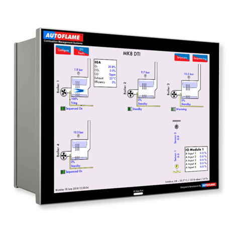
AUTOFLAME Mini Mk8 M.M. User manual

Mini Mk8 M.M.
Installation &
Commissioning Guide


Mini Mk8 MM
Installation and Commissioning Guide
Issued by:
AUTOFLAME ENGINEERING LTD
Unit 1-2, Concorde Business Centre
Airport Industrial Estate, Wireless Road
Biggin Hill, Kent TN16 3YN
Tel: +44 (0)845 872 2000
Fax: +44 (0)845 872 2010
Email: [email protected]
Website: http://www.autoflame.com/
Registered Holder:
Company:
Department:
This manual and all the information contained herein is copyright of
Autoflame Engineering Ltd. It may not be copied in the whole or part without
the consent of the Managing Director.
Autoflame Engineering Ltd’s policy is one of continuous improvement in both
design and manufacture. We therefore reserve the right to amend
specifications and/or data without prior notice. All details contained in this
manual are correct at the time of going to print.


Important Notes
A knowledge of combustion related procedures and commissioning is essential
before embarking work on any of the M.M./E.G.A. systems. This is for safety reasons
and effective use of the M.M./ E.G.A. system. Hands on training is required. For
details on schedules and fees relating to group training courses and individual
instruction, please contact the Autoflame Engineering Ltd. offices at the address listed
on the front.
Short Form - General Terms and Conditions
A full statement of our business terms and conditions are printed on the reverse of all
invoices. A copy of these can be issued upon application, if requested in writing.
The System equipment and control concepts referred to in this Manual MUST be
installed, commissioned and applied by personnel skilled in the various technical
disciplines that are inherent to the Autoflame product range, i.e. combustion, electrical
and control.
The sale of Autoflame’s systems and equipment referred to in this Manual assume that
the dealer, purchaser and installer has the necessary skills at his disposal. i.e. A high
degree of combustion engineering experience, and a thorough understanding of the
local electrical codes of practice concerning boilers, burners and their ancillary
systems and equipment.
Autoflame’s warranty from point of sale is two years on all electronic systems and
components.
One year on all mechanical systems, components and sensors.
The warranty assumes that all equipment supplied will be used for the purpose that it
was intended and in strict compliance with our technical recommendations.
Autoflame’s warranty and guarantee is limited strictly to product build quality, and
design. Excluded absolutely are any claims arising from misapplication, incorrect
installation and/or incorrect commissioning.


CONTENT
1DIMENSIONS AND WIRING .................................................................................. 1
1.1 Mini Mk8 MM .........................................................................................................................1
1.1.1 Fixing Holes and Dimensions...........................................................................................2
1.2 Wiring Schematic.....................................................................................................................3
1.3 Electrical Specifications ...........................................................................................................4
1.3.1 Classifications ..................................................................................................................4
1.3.2 Inputs and Outputs...........................................................................................................4
1.3.3 Cable Specifications ........................................................................................................5
1.3.4 Terminals Description.......................................................................................................5
1.4 Connection Between Mini Mk8 MM and Mk8 EGA................................................................8
1.5 Connection Between Mini Mk8 MM and Mk7 DTI..................................................................9
1.6 Sequencing Connection Diagram ......................................................................................... 10
2OPTIONS AND PARAMETERS ............................................................................... 11
2.1 Options................................................................................................................................. 11
2.2 Parameters............................................................................................................................ 33
3COMMISSIONING FUEL-AIR CURVE ..................................................................... 42
3.1 Overview.............................................................................................................................. 42
3.1.1 Commissioning Procedure............................................................................................. 42
3.2 Installation Checks ................................................................................................................ 43
3.2.1 Commissioning Checks.................................................................................................. 43
3.2.2 Operational Checks...................................................................................................... 43
3.2.3 Installation Precautions ................................................................................................. 43
3.2.4 Maintenance and Servicing.......................................................................................... 43
3.3 Servomotors.......................................................................................................................... 44
3.3.1 Adjusting the Servomotor Potentiometer....................................................................... 44
3.3.2 Servomotor Feedback Voltage..................................................................................... 45
3.3.3 Servomotors – Direction Change.................................................................................. 46
3.3.4 Servomotors with Autoflame Valves ............................................................................. 47
3.4 Commissioning Fuel and Air Positions................................................................................... 48
3.4.1 Starting Commissioning ................................................................................................ 49
3.4.2 Enter CLOSE Position.................................................................................................... 50
3.4.3 Enter OPEN Position ..................................................................................................... 51
3.4.4 Enter START Position..................................................................................................... 52
3.4.5 Phase Hold.................................................................................................................... 53
3.4.6 Add Trim Data During Commissioning.......................................................................... 54

3.4.7 Commissioning VSD...................................................................................................... 56
3.4.8 Set GOLDEN START Position........................................................................................ 57
3.4.9 Set FGR START Position ................................................................................................ 59
3.4.10 Set HIGH Position ......................................................................................................... 61
3.4.11 Set INTER Position......................................................................................................... 62
3.4.12 Set INTER or START Position......................................................................................... 63
3.4.13 Save Commission.......................................................................................................... 64
3.5 Fuel Flow Commissioning...................................................................................................... 65
3.5.1 Calorific Fuel Data........................................................................................................ 68
3.5.2 Conversion Factor for Imperial Gas Flow Meters ......................................................... 69
3.5.3 Correction Factor for Burners Significantly Above Sea Level ....................................... 69
3.5.4 Gas Volume Conversion Factors................................................................................... 70
3.6 Gas/ Air Pressure Commission ............................................................................................. 72
3.7 Single Point Change ............................................................................................................. 73
3.8 Online Changes.................................................................................................................... 78
3.9 General Operation............................................................................................................... 79
3.9.1 Calibrating the Actual Value......................................................................................... 79
3.9.2 External Modulation..................................................................................................... 79
3.9.3 Additional Functions ..................................................................................................... 80
4REMOTE CONTROL .............................................................................................. 81
4.1 Modbus Settings ................................................................................................................... 81
4.2 Configuration........................................................................................................................ 82
4.3 Modbus Addresses............................................................................................................... 83
5ERRORS AND LOCKOUTS .................................................................................... 88
5.1 Errors .................................................................................................................................... 88
5.2 Burner Lockouts .................................................................................................................... 91
5.3 EGA Errors ........................................................................................................................... 95
5.4 Troubleshooting and Further Information ............................................................................. 97
5.4.1 UV Shutter Faults .......................................................................................................... 97
5.4.2 UV Problems................................................................................................................. 97
5.4.3 Snubbers....................................................................................................................... 97
5.4.4 Channel Positioning Error ............................................................................................. 98
5.4.5 Input Fault..................................................................................................................... 98
5.4.7 Setting Conflicts ............................................................................................................ 99
5.4.8 Forced Commission..................................................................................................... 101
6STANDARDS ..................................................................................................... 103


1 Dimensions and Wiring
12.04.2019 Mini Mk8 MM Installation and Commissioning Guide Page 1
1 DIMENSIONS AND WIRING
1.1 Mini Mk8 MM

1 Dimensions and Wiring
Page 2 Mini Mk8 MM Installation and Commissioning Guide 12.04.2019
1.1.1 Fixing Holes and Dimensions

1 Dimensions and Wiring
12.04.2019 Mini Mk8 MM Installation and Commissioning Guide Page 3
1.2 Wiring Schematic
Fuse
Terminals Protected
5A
Mains voltage output terminals 57 – 63
2A
Low voltage terminals and switched neutral outputs

1 Dimensions and Wiring
Page 4 Mini Mk8 MM Installation and Commissioning Guide 12.04.2019
1.3 Electrical Specifications
1.3.1 Classifications
Classification according to EN298
Mains Supply:
230V, +10%/-15%}
47-63 Hz, unit max. consumption 140W
120V, +10%/-15%}
Climate:
Min. Temperature
0
O
C (32
O
F)
Recommended Temperature
Less than 40
O
C (104
O
F)
Max. Temperature
60
O
C (140
O
F)
Humidity
0 to 90% non-condensing
Storage:
Temperature
-20 to 85
O
C (-4 to 185
O
F)
Protection Rating:
The unit is designed to be panel mounted in any orientation and the front facia is
IP65, NEMA4. The back of the unit is IP20, NEMA1.
1.3.2 Inputs and Outputs
Inputs and Outputs
230V Unit:
Outputs
Terminal
57
250mA
Must be connected through contactor
Max Load 5A
58
250mA
Must be connected through contactor
59
1A
0.6 power factor
60
1A
0.6 power factor
61
1A
0.6 power factor
62
1A
0.6 power factor
63
1A
0.6 power factor
78
100mA
To drive relay only – switched neutral
79
100mA
To drive relay/lamp only – switched neutral
120V Unit:
Outputs
Terminal
57
250mA
Must be connected through contactor
Max Load 5A
58
250mA
Must be connected through contactor
59
2A
0.6 power factor
60
2A
0.6 power factor
61
2A
0.6 power factor
62
2A
0.6 power factor
63
2A
0.6 power factor
78
100mA
To drive relay only – switched neutral
79
100mA
To drive relay/lamp only – switched neutral
Note:
•The high and low voltage connections are not safe to touch. Protection against electric shock is
provided by correct installation. CAUTION – ELECTRIC SHOCK HAZARD.
•Control voltage cabling should be maximum 10m, screened (if not screened then less than 1m,
however servomotors can be unscreened up to 10m).
•Any cabling over 10m must have additional surge protection.
•Low voltage cables should be screened cable as specified in section 1.3.3.
•The burner ‘High Limit Stat’ must be a manual reset type.
•There is a lid (back plate) fitted onto the back of the Mini Mk8 MM with a Warning label to
prevent any unauthorised fuse replacements.

1 Dimensions and Wiring
12.04.2019 Mini Mk8 MM Installation and Commissioning Guide Page 5
1.3.3 Cable Specifications
Low Voltage
The screened cable used for low voltage wiring from the MM to the servomotors, detectors and
variable speed drive must conform to the following specification:
U.V. cable length should not exceed 25m; all other screened cable should not exceed 50m.
16/0.2mm PVC insulated overall braid, screened, PVC sheathed.
Sixteen wires per core
Diameter of wires in each core 0.2mm
Rated at 440V AC rms at 1600Hz
DEF 61-12 current rating per core 2.5A
Maximum operating temperature 70oC (158oF)
Nominal conductor area 0.5sq mm per core
Nominal insulation radial thickness on core 0.45mm
Nominal conductor diameter per core 0.93mm
Nominal core resistance at 20oC. 40.1Ω/1000m
Nominal overall diameter per core 1.83mm
Fill factor of braid screen 0.7
Equivalent imperial conductor sizes 14/0.0076
Use the number of cores suitable for the application. A universal part numbering system appears to
have been adopted for this type of cable as follows:
16-2-2C 2 Core
16-2-3C 3 Core
16-2-4C 4 Core
16-2-6C 6 Core
16-2-8C 8 Core
(5 Core not readily available)
Note: If using 4 Core cable and interference is detected, use 2 sets of 2 Core.
Data Cable
Data cable must be used for communication connections between MMs for sequencing applications as
well as between MMs to EGAs, MMs to a DTI and DTI to BMS systems.
Communication cable should not exceed 1km.
Types of data cable that can be used:
1 Beldon 9501 for 2-core shielded cable (1 twisted pair)
2 Beldon 9502 for 4-core shielded cable (2 twisted pairs)
3 STC OS1P24
Samples are available upon request. Low voltage and data cable can be ordered directly from
Autoflame Engineering, please contact Autoflame Sales Department.
When using a VSD, please review the manufacturer’s guidelines on installations to prevent EMC
including the recommendations for reactors and filters.

1 Dimensions and Wiring
Page 6 Mini Mk8 MM Installation and Commissioning Guide 12.04.2019
1.3.4 Terminals Description
S
All terminals marked S are internally connected provided for connections to the various
screened cables.
1
Current Input, 0-20mA/ 4-20mA. For channel 4 only. Can be connected to the current output
of a VSD or tachometer system or 4-20mA servomotor feedback
2
Voltage Input, 0-10V. For channel 4 only. Can be connected to the voltage output of a VSD
or tachometer system
3
0V common for Terminals 1 or 2
10
Current Output, 0-20mA/ 4-20mA. For channel 4 only. Can be connected to the current
input of a VSD or tachometer system or 4-20mA servomotor feedback
11
Voltage Output, 0-10V. For channel 4 only. Can be connected to the voltage input of a VSD
or tachometer system
12
0V common for Terminals 10 or 11
21, 22
Connections to an Autoflame self-check UV sensor
25, 26
Communications port connections to an Exhaust Gas Analyser (EGA)
27, 28
Communications port connections for DTI and/or IBS, or Modbus
29, 30
Digital communications connections to an Autoflame IR scanner (MM70017), Autoflame air
pressure sensor and/or Autoflame gas pressure sensor
37
0V supply to an Autoflame temperature or pressure detector or 0-10V external modulation
input
38
Signal input from an Autoflame temperature or pressure detector or 0-10V external
modulation input
39
12V supply to an Autoflame pressure detector
40
0V supply to channel 1 and channel 2 servomotors
41
+12V supply to channel 1 and channel 2 servomotors
42
Signal from channel 1 servomotor, indicating position
43
Signal from channel 2 servomotor, indicating position
44
Signal from channel 3 servomotor, indicating position
46
0V Supply to channel 3 servomotor
47
+12V Supply to channel 3 servomotor
48, 49
+15V connections to an Autoflame IR scanner (MM70017), Autoflame air pressure sensor
and/or Autoflame gas pressure sensor
50, 51
Connections to an Autoflame UV sensor

1 Dimensions and Wiring
12.04.2019 Mini Mk8 MM Installation and Commissioning Guide Page 7
64
Connections to a flame rod
53
Mains voltage input – burner on/off signal, running interlock circuit
54
Mains voltage input – air proving switch
55
Mains voltage input - proving circuits, e.g. gas valve proof of closure
57
Mains voltage output – call for heat
58
Mains voltage output – burner motor
59
Mains voltage output – start/pilot valve
60
Mains voltage output – main fuel valve 1
61
Mains voltage output – main fuel valve 2
62
Mains voltage output – vent valve
63
Mains voltage output – ignition transformer
66
Mains supply – earth
67
Main supply – neutral
68
Mains supply – live/hot
69
Mains voltage output, power to servomotors and/or stepdown transformer
70
Switched neutral – drives channel 1 servomotor clockwise
71
Switched neutral – drives channel 1 servomotor counter clockwise
72
Switched neutral – drives channel 2 servomotor clockwise
73
Switched neutral – drives channel 2 servomotor counter clockwise
74
Switched neutral – drives channel 3 servomotor clockwise
75
Switched neutral – drives channel 3 servomotor counter clockwise
78
Switched neutral –2-port valve for IBS operation
79
Switched neutral – alarm output for MM lockout/MM error/EGA error
80
Start position interlock/ night setback input/ reduced setpoint input
81
Purge interlock/ low flame hold input/ purge pressure proving
82
Warming stat/ valve proving mains input
89
Mains voltage input – selects fuel 1 curve
90
Mains voltage input – selects fuel 2 curve

1 Dimensions and Wiring
Page 8 Mini Mk8 MM Installation and Commissioning Guide 12.04.2019
1.4 Connection Between Mini Mk8 MM and Mk8 EGA EVO

1 Dimensions and Wiring
12.04.2019 Mini Mk8 MM Installation and Commissioning Guide Page 9
1.5 Connection Between Mini Mk8 MM and Mk8 DTI

1 Dimensions and Wiring
Page 10 Mini Mk8 MM Installation and Commissioning Guide 12.04.2019
1.6 Sequencing Connection Diagram
Other manuals for Mini Mk8 M.M.
2
This manual suits for next models
1
Table of contents
Other AUTOFLAME Measuring Instrument manuals
Popular Measuring Instrument manuals by other brands
Vixen Horns
Vixen Horns VXA7240 installation guide

SellEton Scales
SellEton Scales SL-918 user manual

Hioki
Hioki HiTESTER 3415-02 instruction manual

Maxwell Digital Multimeters
Maxwell Digital Multimeters 25601 user manual

Vega
Vega INFO-1 operating manual

Precision Digital Corporation
Precision Digital Corporation PD6060 instruction manual
