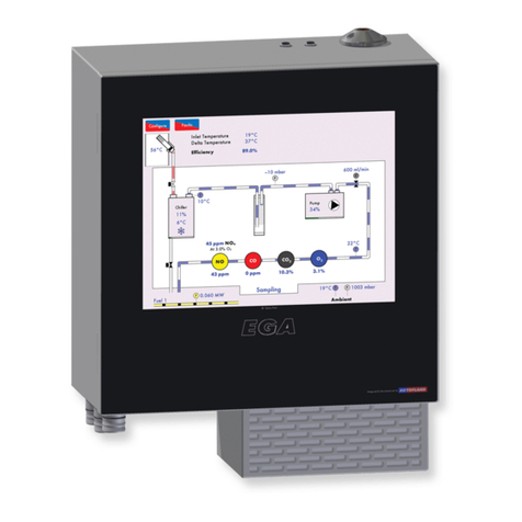
AUTOFLAME Mk7 User manual

M
S
e
M
k7
D
e
t-Up
G
D
.T.I.
G
uide


Mk7 D.T.I.
Set-Up Guide
Issued by:
AUTOFLAME ENGINEERING LTD
Unit 1-2, Concorde Business Centre
Airport Industrial Estate, Wireless Road
Biggin Hill, Kent TN16 3YN
Tel: +44 (0)845 872 2000
Fax: +44 (0)845 872 2010
Email: [email protected]
Website: http://www.autoflame.com/
Registered Holder:
Company:
Department:
This manual and all the information contained herein is copyright of
Autoflame Engineering Ltd. It may not be copied in the whole or part without
the consent of the Managing Director.
Autoflame Engineering Ltd’s policy is one of continuous improvement in both
design and manufacture. We therefore reserve the right to amend
specifications and/pr data without prior notice. All details contained in this
manual are correct at the time of going to print.


Important Notes
A knowledge of combustion related procedures and commissioning is essential before
embarking work on any of the M.M./E.G.A. systems. This is for safety reasons and
effective use of the M.M./ E.G.A. system. Hands on training is required. For details on
schedules and fees relating to group training courses and individual instruction, please
contact the Autoflame Engineering Ltd. offices at the address listed on the front.
Short Form - General Terms and Conditions
A full statement of our business terms and conditions are printed on the reverse of all
invoices. A copy of these can be issued upon application, if requested in writing.
The System equipment and control concepts referred to in this Manual MUST be installed,
commissioned and applied by personnel skilled in the various technical disciplines that
are inherent to the Autoflame product range, i.e. combustion, electrical and control.
The sale of Autoflame’s systems and equipment referred to in this Manual assume that
the dealer, purchaser and installer has the necessary skills at his disposal. i.e. A high
degree of combustion engineering experience, and a thorough understanding of the
local electrical codes of practice concerning boilers, burners and their ancillary systems
and equipment.
Autoflame’s warranty from point of sale is two years on all electronic systems and
components.
One year on all mechanical systems, components and sensors.
The warranty assumes that all equipment supplied will be used for the purpose that
it was intended and in strict compliance with our technical recommendations. Auto-
flame’s warranty and guarantee is limited strictly to product build quality, and design.
Excluded absolutely are any claims arising from misapplication, incorrect installation
and/or incorrect commissioning.

Contents
1MK7 DATA TRANSFER INTERFACE MODULE ............................................................. 1
1 Overview of the Mk7 D.T.I. .........................................................................................................1
1.1.1 Introduction to the Mk7 D.T.I...........................................................................................1
1.1.2 Information Available from Mk7 D.T.I. ............................................................................1
1.2 Fixing Holes and Dimensions...................................................................................................4
2SET-UP AND CONNECTIONS .................................................................................... 5
2.1 Wiring......................................................................................................................................5
2.1.1 Mk7 D.T.I. Wiring Diagram .............................................................................................5
2.1.2 System Schematic ............................................................................................................6
2.1.3 M.M. Modules Connection ..............................................................................................7
2.1.4 Mk7 M.M. and Mk8 E.G.A. with Mk7 D.T.I. ...................................................................8
2.2 Mk7 D.T.I. Set-Up ....................................................................................................................9
2.2.1 Mk7 M.M. Options and Parameters................................................................................9
2.2.2 Mini Mk8 M.M. Options and Parameters..................................................................... 12
2.2.3 Configuring the Boiler Room......................................................................................... 15
2.2.4 D.T.I. Setup ................................................................................................................... 22
2.2.5 Deleting Boilers and I/O Modules................................................................................ 25
2.2.6 Network Set-Up ............................................................................................................ 30
2.3 Mk7 D.T.I. Connections ........................................................................................................ 32
2.3.1 PC Connection .............................................................................................................. 32
2.3.2 Network Connection..................................................................................................... 33
2.3.3 Pinging the D.T.I............................................................................................................ 34
2.3.4 RS422 Connection........................................................................................................ 35
3ANALOGUE AND DIGITAL INPUTS/OUTPUTS ........................................................ 36
3.1 Mk7 Universal Input/ Output Module .................................................................................. 36
3.1.1 Introduction................................................................................................................... 36
3.1.2 Wiring and Dimensions................................................................................................. 37
3.1.3 Set-Up I/O Modules on Mk7 D.T.I. .............................................................................. 39
4MODBUS............................................................................................................... 48
4.1 M.M.
Read Addresses .......................................................................................................... 48
4.2 E.G.A. Read Addresses ........................................................................................................ 56
4.3 Input/ Output Modules Read Addresses .............................................................................. 58
4.4 Read/Write Addresses ......................................................................................................... 61
4.4.1 M.M. Read/Write Addresses ....................................................................................... 61
4.4.2 Analogue and Digital I/O Read/Write Addresses ....................................................... 61

4.5 Information, Errors and Lockouts .......................................................................................... 62
4.5.1 Digital Inputs (1x Reference) ........................................................................................ 62
4.5.2 Analogue Inputs (3x References) ................................................................................. 63
4.5.3 Error and Lockout Codes .............................................................................................. 64
4.5.4 Water Level .................................................................................................................. 68
5INTERACTING WITH THE MK7 D.T.I. ....................................................................... 69
5.1 Burner Information................................................................................................................ 69
5.2 M.M. Display Screen............................................................................................................ 71
5.3 Fault Logs.............................................................................................................................. 74
5.4 M.M. I.B.S Screen................................................................................................................. 75
5.5 Display Logs ......................................................................................................................... 76
5.6 E.G.A. Display Screen .......................................................................................................... 78
5.7 I.B.S Information ................................................................................................................... 79


1 Mk7 Data Transfer Interface Module
10.08.2015 Mk7 D.T.I. Set-Up Guide Page 1
1 MK7 DATA TRANSFER INTERFACE MODULE
1 Overview of the Mk7 D.T.I.
1.1.1 Introduction to the Mk7 D.T.I.
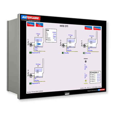
The Autoflame Data Transfer Interface (D.T.I.) is the gateway for communications between the M.M.
and E.G.A. range of products. All of the M.M. operational data, of up to ten M.Ms in one location, can
be collected by the D.T.I. The information gathered is available for transmission to an external source
via RS422 and Ethernet data links. The data gathered by the Mk7 D.T.I. can be collected and viewed
using the included CEMS Audit software, which allows data collection over a Local Area Network
(LAN), or over the internet.
Up to a maximum of ten M.M. modules, can be connected to one D.T.I. module. This can be a
combination of Mk7 M.M. modules and Mini Mk8 M.M. modules. It is also possible to receive data
from up to 10 E.G.A.s for emissions data. To accommodate the status information from other plant
related equipment, the D.T.I. can communicate with up to ten Mk6 Analogue and ten Mk6 Digital
Input/ Output Modules, or ten Mk7 Universal Input/ Output modules. The information gathered by the
D.T.I. from each system is then available for transmission to the Building Management System or
Energy Management System (BMS or EMS). This is done through the RS422 link or Ethernet to send
data via Modbus communications. Typical remote B.M.S. information and operational facilities are
subject to the particular site and management system requirements.
The Autoflame network operates using a two core screened cable and features dedicated data ports
for RS422 and Ethernet connections. The Mk7 D.T.I. poles each item on the network periodically,
storing up-to-date information every 2 seconds. The D.T.I. then outputs to defined Modbus addresses,
which are then available to third party systems like a B.M.S. The 10.4” touch-screen displays the
operational status of the D.T.I.’s communications, with corresponding error conditions in the event of a
communication failure.
1.1.2 Information Available from Mk7 D.T.I.
The Mk7 D.T.I. displays information from the Mk7 M.M., Mini Mk8 M.M., Mk8 E.G.A., and the Water
Level control. Remote on/off control of the burners can also be achieved as well as the adjustment of
the temperature or pressure setpoints and the sequence order. Through the D.T.I. touch screen, CEMS
Audit software and via Modbus, the following information is available:
Mk7 D.T.I. Input Values
Enable/disable burner
Change individual required setpoint
Change global required setpoint
Select lead boiler
Shuffle sequencing (not Modbus)
Set load index (firing rate)
Label and control input/outputs (not Modbus)
Mk7 M.M.
Actual boiler temperature (deg. C/F) or pressure (Bar/PSI)
Required setpoint i.e. required boiler temperature (deg. C/F) or pressure (Bar/PSI)
Burner on/off status
Burner firing rate (%)
Fuel selected
Burner rating

1 Mk7 Data Transfer Interface Module
Page 2 Mk7 D.T.I. Set-Up Guide 10.08.2015
Fuel flow metering values
Load detector type (temperature/pressure)
16 lockout and error history with date and conditions
Auto/hand/low flame hold operation
Number of channels used
Channe1, 2, 3, 4, 7, servomotor angle
Channel 5, 6 output and input signals to VFD with feedback history
Burner firing status phase (off, standby, purge, ignition, firing etc.)
Lead/lag boiler status
Sequence order
Sequence status (on, standby warming, off)
Enabled/disabled status
Total hours run
Number of start-ups per fuel
Online and commissioned gas/ oil pressure
Online and commissioned air pressure
UV scanner signal history
Mk8 E.G.A.
E.G.A. operation optioned
Standalone/M.M. operation
Flue gas O2present value
Flue gas CO2present value
Flue gas CO present value
Flue gas NO present value
Flue gas NO2present value (if optioned)
Flue gas SO2present value (if optioned)
Flue gas O2commissioned value
Flue gas CO2commissioned value
Flue gas CO commissioned value
Flue gas NO commissioned value
Flue gas NO2commissioned value (if optioned)
Flue gas SO2commissioned value (if optioned)
Flue gas exhaust temperature
Ambient temperature
Flue gas delta temperature
E.G.A. errors
Chiller condition
Current emissions by weight and volume (O2, CO2, CO, NO, SO3, H2O, N2, Total)
Totalised emissions by weight and volume (O2, CO2, CO, NO, SO3, H2O, N2, Total)
Heat input, heat loss and net useful heat
Net efficiency, gross efficiency and delta temperature
Fuel flow rates, instantaneous and totalised for up to 2 years
Fuel consumption, fuel costs instantaneous and totalise for up 2 years

1 Mk7 Data Transfer Interface Module
10.08.2015 Mk7 D.T.I. Set-Up Guide Page 3
Mini Mk 8 M.M.
Actual boiler temperature (deg. C/F) or pressure (Bar/PSI)
Required setpoint i.e. required boiler temperature (deg. C/F) or pressure (Bar/PSI)
Burner on/off status
Burner firing rate (%)
Fuel selected
Burner rating
Fuel flow metering values
Load detector type (temperature/pressure)
16 lockout and error history with date and conditions
Auto/hand/low flame hold operation
Number of channels used
Channe1, 2, 3 servomotor angle
Channel 4 output and input signals to VFD with feedback history
Burner firing status phase (off, standby, purge, ignition, firing etc.)
Lead/lag boiler status
Sequence order
Sequence status (on, standby warming, off)
Enabled/disabled status
Total hours run
Number of start-ups per fuel
Water Level Control
Actual water level signal value for probe 1 and 2
Average water level signal of probes
Commissioned end of probe position
Commissioned 2nd low position
Commissioned 1st low position
Commissioned 1st low pre-alarm position
Commissioned control point position
Commissioned pump on/ pump off positions
Commissioned high water pre-alarm position
Commissioned high water position
15 First out annunciation inputs status
Instantaneous and totalised steam flow metering
Feedwater temperature
Feedwater valve position
Feedwater pump status
Feedwater VSD output
Steam temperature and pressure
Top blow down status and operation
TDS actual value
TDS valve position
TDS target value
16 Water level/ Expansion alarms conditions and date
Bottom blowdown operation

1 Mk7 Data Transfer Interface Module
Page 4 Mk7 D.T.I. Set-Up Guide 10.08.2015
1.2 Fixing Holes and Dimensions

2 Set-Up and Connections
10.08.2015 Mk7 D.T.I. Set-Up Guide Page 5
2 SET-UP AND CONNECTIONS
2.1 Wiring
2.1.1 Mk7 D.T.I. Wiring Diagram
Figure 2.1.1.i Mk7 D.T.I. Wiring Diagram
Electrical Specifications:
Max power for the Mk7 D.T.I. power supply is 184W.
Figure 2.1.1.ii Mk7 D.T.I. Board

2 Set-Up and Connections
Page 6 Mk7 D.T.I. Set-Up Guide 10.08.2015
2.1.2 System Schematic

2 Set-Up and Connections
10.08.2015 Mk7 D.T.I. Set-Up Guide Page 7
2.1.3 M.M. Modules Connection

2 Set-Up and Connections
Page 8 Mk7 D.T.I. Set-Up Guide 10.08.2015
2.1.4 Mk7 M.M. and Mk8 E.G.A. with Mk7 D.T.I.

2 Set-Up and Connections
10.08.2015 Mk7 D.T.I. Set-Up Guide Page 9
2.2 Mk7 D.T.I. Set-Up
2.2.1 Mk7 M.M. Options and Parameters
To get the Mk7 D.T.I. to communicate with the Mk7 M.M., the right communication settings need to be
set on the Mk7 M.M. The following options and parameters need to be set.

2 Set-Up and Connections
Page 10 Mk7 D.T.I. Set-Up Guide 10.08.2015
Option No.
Factory Setting
Option Value
Description
3 0 DTI Comms Mode
0 Mk6 DTI - 9600bps
1 Mk7 DTI - 19200bps
16 0 Lead/Lag (IBS) and DTI: A lead boiler can be selected by connecting a line voltage to terminal 88 on
the appropriate MM. Only 1 MM may be selected as lead boiler at a time, or the sequencing will
not operate. The lead boiler can be selected via the DTI. However, for this to be effective all the MM
units on the system must have Terminal 88 volt free. Line voltage on Terminal 88 overrides the DTI
command.
0 No sequencing - MM units still communicate and can be seen on the DTI.
1 Sequencing enabled - MM units will respond to sequencing commands. Lead boiler is selected by a line
voltage on terminal 88.
2 Setpoint & enable/disable commands accepted from DTI.
3 Both 1 and 2.
Note
:
Accurate fuel flow metering must be entered for sequencing to operate. An RS485 data cable
(Belden 9501) must be connected between each MM unit (see section 2.17.3.4 for correct connection).
30 50 DTI Required Setpoint Minimum Limit: If the system is being used with a DTI a maximum and
minimum limit for the required setpoint must be set. If a value is received from the DTI that is outside
these limits, it will be ignored and the system uses its previous required setpoint. Practical range is
limited to range of sensor selected.
5 - 9990 If Centigrade, Fahrenheit or PSI units effective.
0.5 - 999.0 If Bar units effective.
31 100 DTI Required Setpoint Maximum Limit:
5 - 9990 If Centigrade, Fahrenheit or PSI units effective.
0.5 - 999.0 If Bar units effective.
33 1 MM Identification: The identification number must be set on all MM Units in the boiler house. If
not, then problems will occur with sequencing/twin burner and with the DTI communications. Each
unit must have a different identification number.
34 5 Rating of Burner:
1 - 999 See Option 77 for units.
77 0 Burner rating units: Display purposes only for fuel flow metering.
0 KW x 100 /hr
1 Kg x 100 /hr
2 MW /hr
3 Btu x 100 /hr
4 Hp x 100 /hr
5 lbs x 100 /hr
6 Btu x 1000 /hr
7 Hp x 10 /hr
8 lbs x 1000 /hr
9 Btu x 1000 000 /hr

2 Set-Up and Connections
10.08.2015 Mk7 D.T.I. Set-Up Guide Page 11
Parameter No.
Factory Setting
Option Value
Description
57 0 0 - 10 Sequencing: Highest MM ID. This parameter speeds up communications between MM's
when sequening.
101 0 Shuffle sequencing:
0 Disabled
1 Sequence order changed from DTI.

2 Set-Up and Connections
Page 12 Mk7 D.T.I. Set-Up Guide 10.08.2015
2.2.2 Mini Mk8 M.M. Options and Parameters
To get the Mk7 D.T.I. to communicate with the Mini Mk8 M.M., the right communication settings need
to be set on the Mini Mk8 M.M. The following options and parameters need to be set.
Other manuals for Mk7
3
Table of contents
Other AUTOFLAME Measuring Instrument manuals
Popular Measuring Instrument manuals by other brands
Vixen Horns
Vixen Horns VXA7240 installation guide
SellEton Scales
SellEton Scales SL-918 user manual

Hioki
Hioki HiTESTER 3415-02 instruction manual

Maxwell Digital Multimeters
Maxwell Digital Multimeters 25601 user manual

Vega
Vega INFO-1 operating manual
Precision Digital Corporation
Precision Digital Corporation PD6060 instruction manual
