AUTOFLAME Mk7 User manual

Mk7 Manual:
E.G.A. Set-Up and Trim
Guide


Mk7 Manual:
E.G.A. Set-Up and Trim Guide
Issued by:
AUTOFLAME ENGINEERING LTD
Unit 1-2, Concorde Business Centre
Airport Industrial Estate, Wireless Road
Biggin Hill, Kent TN16 3YN
Tel: +44 (0)845 872 2000
Fax: +44 (0)845 872 2010
Email: [email protected]
Website: http://www.autoflame.com/
Registered Holder:
Company:
Department:
This manual and all the information contained herein is copyright of
Autoflame Engineering Ltd. It may not be copied in the whole or part without
the consent of the Managing Director.
Autoflame Engineering Ltd’s policy is one of continuous improvement in both
design and manufacture. We therefore reserve the right to amend
specifications and/pr data without prior notice. All details contained in this
manual are correct at the time of going to print.


Important Notes
A knowledge of combustion related procedures and commissioning is essential before
embarking work on any of the M.M./E.G.A. systems. This is for safety reasons and
effective use of the M.M./ E.G.A. system. Hands on training is required. For details on
schedules and fees relating to group training courses and individual instruction, please
contact the Autoflame Engineering Ltd. offices at the address listed on the front.
Short Form - General Terms and Conditions
A full statement of our business terms and conditions are printed on the reverse of all
invoices. A copy of these can be issued upon application, if requested in writing.
The System equipment and control concepts referred to in this Manual MUST be installed,
commissioned and applied by personnel skilled in the various technical disciplines that
are inherent to the Autoflame product range, i.e. combustion, electrical and control.
The sale of Autoflame’s systems and equipment referred to in this Manual assume that
the dealer, purchaser and installer has the necessary skills at his disposal. i.e. A high
degree of combustion engineering experience, and a thorough understanding of the
local electrical codes of practice concerning boilers, burners and their ancillary systems
and equipment.
Autoflame’s warranty from point of sale is two years on all electronic systems and
components.
One year on all mechanical systems, components and sensors.
The warranty assumes that all equipment supplied will be used for the purpose that
it was intended and in strict compliance with our technical recommendations. Auto-
flame’s warranty and guarantee is limited strictly to product build quality, and design.
Excluded absolutely are any claims arising from misapplication, incorrect installation
and/or incorrect commissioning.


Contents
1INTRODUCTION ......................................................................................... 1
1.1 Overview and Benefits.............................................................................................................1
1.1.1 Features and Benefits.......................................................................................................1
1.1.2 System Operation............................................................................................................1
1.2 3-Parameter Trim .....................................................................................................................2
2WIRING AND COMPONENTS...................................................................... 3
2.1 Electrical Schematics................................................................................................................3
2.1.1 Interconnection between E.G.A. and M.M. Module........................................................3
2.1.2 CEMS E.G.A. with D.T.I. ..................................................................................................4
2.1.2.1 Wiring..........................................................................................................................5
2.1.3 Interconnection between Stand-Alone Mk7 E.G.A. and Mk7 D.T.I .................................6
2.2 Components.............................................................................................................................7
2.2.1 Inside View ......................................................................................................................7
2.2.2 Inside View Schematic .....................................................................................................8
2.3 Cell Characteristics ..................................................................................................................9
2.3.1 O2Cell .............................................................................................................................9
2.3.2 CO, NO, NO2and SO2Cells........................................................................................ 10
2.3.3 CO2 Sensor................................................................................................................. 10
3SET-UP...................................................................................................... 11
3.1 E.G.A. Set-Up ....................................................................................................................... 11
3.1.1 Sampling Screen........................................................................................................... 11
3.1.2 Mk7 E.G.A. Settings ..................................................................................................... 13
3.1.3 Cell Status Screen ......................................................................................................... 14
3.1.4 Fault History.................................................................................................................. 15
3.1.5 Factory Settings Screen ................................................................................................ 16
3.1.6 4-20mA Set-up.............................................................................................................. 17
3.1.7 Operating Mode Set-up................................................................................................ 18
3.1.8 Cell Calibration............................................................................................................. 19
3.1.9 Time and Date .............................................................................................................. 21
3.1.10 Change Password......................................................................................................... 22
3.1.11 Emissions History Screens ............................................................................................. 23
3.2 Trim Settings.......................................................................................................................... 25
3.2.1 Relevant M.M. Options ................................................................................................ 25
3.2.2 Relevant M.M. Parameters ........................................................................................... 28
3.2.3 Commissioning Procedure............................................................................................. 31

3.3 Mk7 E.G.A. Trim................................................................................................................... 32
3.3.1 Trim Operation ............................................................................................................. 32
3.3.2 Quick Commission ........................................................................................................ 34
3.3.3 Trim Timing Operation .................................................................................................. 36
3.3.4 Graphical Trim Operation ............................................................................................ 37
3.3.5 Channel 5 Trim ............................................................................................................. 38
3.3.5 Combustion Efficiency Calculations .............................................................................. 38
3.4 Combustion Limits ................................................................................................................. 39
3.4.1 Overview of Combustion Limits..................................................................................... 39
3.4.2 Standard Limits ............................................................................................................. 39
3.4.3 Absolute Limits .............................................................................................................. 39
3.4.4 Combustion Limits Control Functions............................................................................ 39
3.4.5 O2Limits Example ......................................................................................................... 40
3.4.6 NO Limits Example ....................................................................................................... 41
3.4.7 CO Limit Example ......................................................................................................... 42
3.4.8 Temperature Limits Example ......................................................................................... 43
4DIMENSIONS AND EQUIPMENT................................................................ 44
4.1 Mk7 E.G.A. Dimensions........................................................................................................ 44
4.2 Technical Specifications ........................................................................................................ 45
4.3 Sampling Probe .................................................................................................................... 46
4.3.1 Installation and Maintenance ....................................................................................... 46
4.3.2 Sampling Probe Assembly ............................................................................................ 47
4.3.3 Sampling Probe Internal Filter ...................................................................................... 48
4.3.4 Sampling Probe Maintenance ...................................................................................... 49
4.3.5 Servicing E.G.A. Sampling Probe ................................................................................. 49
4.4 Ancillary Equipment.............................................................................................................. 50
4.4.1 External Particulate Filter .............................................................................................. 50
4.4.2 Air Inlet Filter ................................................................................................................ 52
4.4.3 Chilled Environmental Enclosure................................................................................... 53
5ERROR CHECKING AND SELF-DIAGNOSTICS .............................................. 54
5.1 Key to Errors......................................................................................................................... 54
5.2 Troubleshooting .................................................................................................................... 56
5.2.1 Ambient Conditions ...................................................................................................... 56
5.2.2 Fuses............................................................................................................................. 56
5.2.3 O2Reading ................................................................................................................... 56
5.2.4 Filter Fault ..................................................................................................................... 56

5.2.5 Trim Delay .................................................................................................................... 57
5.2.6 Assembly of Dry Filter................................................................................................... 57
5.3 E.G.A. Best Practice .............................................................................................................. 58
5.3.1 Servicing the E.G.A....................................................................................................... 59
5.3.2 Shipping the E.G.A. ...................................................................................................... 59
6MK7 CEMS E.G.A. ..................................................................................... 60
6.1 Overview of the Mk7 CEMS E.G.A. ..................................................................................... 60
6.1.1 C.E.M.S. Upgrade ........................................................................................................ 60
6.2 CEMS Set-Up ........................................................................................................................ 61
6.2.1 Fuel Selection................................................................................................................ 61
6.2.2 Fuel Flow Source .......................................................................................................... 63
6.2.3 Unit Measurement ........................................................................................................ 64
6.3 CEMS Data Screens.............................................................................................................. 65
6.4 CEMS Energy Audits ............................................................................................................ 69


1 INTRODUCTION
1.1 Overview and Benefits
1.1.1 Features and Benefits
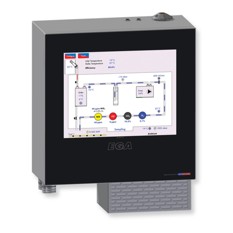
The Mk7 Exhaust Gas Analyser (E.G.A.) monitors the emissions in the flue produced from the
burner/boiler system. The E.G.A. can improve combustion, increase efficiency, reduce fuel
consumption and improve safety through its 3 parameter trim function and combustion safety limits.
1. Stand-Alone: When in stand-alone mode, the E.G.A. can be used without a Micro-Modulation
(M.M.) module to monitor the combustion gases. The M.M. trim function and the combustion
safety limits are not activated in this stand-alone mode of operation. The emissions levels can
be accessed via the full colour E.G.A. touch screen.
2. With M.M.: When interfaced with an M.M., the E.G.A. can monitor emissions or the 3-
parameter combustion trim and safety limits can be activated. The emissions levels are
monitored by the E.G.A. and the M.M. makes small adjustments to the air damper to trim the
online exhaust gas data back to the commissioned values. The E.G.A. information is accessible
through the full colour E.G.A. touch screen, the Data Transfer Interface module (D.T.I.), or 6 x
4-20mA signals.
The main benefits of the E.G.A. include the ability to monitor the exhaust gases and bring them to the
safe commissioned levels. Setting the combustion limits on the M.M. in conjunction with the E.G.A.
prevents unsafe combustion scenarios, reducing the fuel consumed in bad combustion.
1.1.2 System Operation
The Mk7 E.G.A. samples the combustion gases via the stack mounted sampling probe (purchased
separately from the analyser). The exhaust gases are drawn from the stack by a pump mounted
internally within the analyser. Only the supplied sample tubing should be used between the sampling
probe and analyser. The internal diameter of the sampling tube is 3mm; if a large diameter tubing is
used the sample gas remains resident in the tubing for a longer period. The E.G.A. will then not be able
to respond in time to combustion changes, resulting in incorrect operation of the trim function.
Once the exhaust gases have entered the E.G.A. the chiller block reduces their temperature and dries
the sample to remove the condensation from the gases prior to entering the cells. The condensate
accumulated in the chiller unit is drained every 4 minutes when running, and every 10 minutes when
the E.G.A. is in idle mode, automatically through the drain solenoid.
The exhaust gas is then filtered through the dry filter, which is a fine filter used to remove any dust
particles carried over from the cooling process. If the burner is firing on heavy or dirty oil, an external
particulate filter must be used to remove the excess dirt particles. On leaving the filter, the exhaust gas
pressure is checked again to ensure that a vacuum is maintained prior to entering the pump and on
exiting the pump, the pressure produced by the pump is checked. Both these pressure sensors modulate
the flow rate of the sample into the E.G.A. for consistent operation. Once the exhaust gases have been
conditioned, they are ready for an accurate sampling by the cells. After the gases have been sampled
by all the cells, the remaining sample is pumped out of the E.G.A. from the clear tubing at the bottom
of the E.G.A. casing.
Note: The E.G.A. needs to vent to atmosphere via the drain solenoid on the bottom; this is also where
the E.G.A. performs its air calibrations. Care should be taken to ensure the outlet is not restricted or
that contamination from exhaust gas occurs.
1 Introduction
September 2014
Mk7 Manual: E.G.A. Set-Up and Trim Guide
Page 1

1.2 3-Parameter Trim
The 3-parameter trim function can be enabled when the Mk7 E.G.A. is used in conjunction with an
M.M. module to manage the combustion. When the E.G.A. detects any differences in the online
exhaust gas readings to the original commissioned values, the trim function will make small corrections
to the air damper (and channel 5 if optioned for trim), to bring those online values back to the
commissioned readings. The trim function controls the combustion of the burner by adding air (air rich)
or taking away air (fuel rich) from the commissioned air positions to keep the volume of O2, CO2and
CO close to their commissioned values without compromising safety. The air rich and fuel rich limits are
set by adding trim data when commissioning the burner or through single point change for ‘quick
commission.’ This trim data is translated into a combustion map, which shows how the burner reacts
when air is added or removed from the combustion process during commissioning. The Autoflame
system continually monitors 3 parameters O2, CO2and CO to create the safest and most efficient way
of trimming the combustion process.
Ingress of tramp air through an ill-fitting boiler or flue section will distort the O2reading and show an
increase in this value. This results in the E.G.A. reading the tramp air influence in the sample rather than
just the actual combustion gases.
Single parameter O2trim systems would see both of these conditions as rich (excess air) combustion
and start to trim back on the air by closing the air damper. In reality this trim process is not trimming the
combustion gases at this point, but is in fact trimming the exhaust gases with the excess O2. This can
potentially lead to the formation of excessive amounts of CO but more importantly this can lead to
incomplete combustion with dangerous consequences.
Similarly, single parameter CO2trim systems would interpret of air as lower CO2levels in the flue,
inflicting similar dangerous conditions in the boiler.
Another benefit of the 3 parameter trim is that the E.G.A. is continually measuring the formation of CO
compared to its commissioned value. A higher CO reading can be contributed to both lean and rich
combustion. A lack of air will produce incomplete combustion and the formation of CO. Also, excess
air around the flame envelope can chill the flame edge causing incomplete combustion and higher CO
levels.
By referencing all 3 parameters against mapped combustion performance the burner can be trimmed
back to the original commissioned values whilst maintaining the highest degree of safety.
When the trim function adds air to bring back the combustion to the commissioned values, as the
burner modulates to a new position, the deviation in air damper movement is added to each air
position. In this way, optimum combustion is maintained during modulation, through carry forward trim.
As a safety feature, as the air is being taken away, the fuel to air ratio will return back to the
commissioned positions when the burner modulates, for every 10 degrees of fuel valve movement.
Once this new position is held the system will determine whether the air damper should be closing. This
ensures safe combustion at all times without any compromise.
1 Introduction
Page 2
Mk7 Manual: E.G.A. Set-Up and Trim Guide
September 2014

DATA CABLE
NEUTRAL EARTH
LIVE
CONTROL
FUSE
to DTI
CH. 6 +
CH. 5 +
CH. 4 +
CH. 3 +
CH. 2 +
CH. 1 +
4-20mA
CH.1- CH.6
Analogue
Output g
SCREEN
RED
BLACK
2 WIRING AND COMPONENTS
2.1 Electrical Schematics
2.1.1 Interconnection between E.G.A. and M.M. Module
2 Wiring and Components
September 2014
Mk7 Manual: E.G.A. Set-Up and Trim Guide
Page 3

2 Wiring and Components
2.1.2 CEMS E.G.A. with D.T.I.
The Mk7 CEMS E.G.A. is the Continuous Emissions Monitoring System; it logs the exhaust gas data for
up to 2 years including the gas readings, flue temperature and calculated efficiency.
When using a standalone CEMS E.G.A. a direct connection as shown in section 2.1.3 will be required
to view and log up to 2 years of data on the D.T.I. The D.T.I. will need to be setup as ‘E.G.A. direct’
through the ‘Edit Boiler’ screen and the E.G.A. setup for standalone operation (E.G.A. selects fuel).
Using the CEMS E.G.A. in conjunction with the Mk7 M.M. module and D.T.I, a data link will be
required between the M.M. and E.G.A. and from the E.G.A. to the D.T.I. (see section 2.1.2.1). The
D.T.I. will need to be setup as ‘E.G.A. Direct’ not ‘E.G.A. through M.M.’
When using a Standard E.G.A. (without CEMS) the D.T.I. can be setup as ‘E.G.A. Direct’ or ‘through
M.M.’, however the data logging is only for 24hrs.
Page 4
Mk7 Manual: E.G.A. Set-Up and Trim Guide
September 2014

2.1.2.1 Wiring
2 Wiring and Components
September 2014
Mk7 Manual: E.G.A. Set-Up and Trim Guide
Page 5
DTI
3-WAY
PLUG
S -+
E N L 3-WAY
PLUG POWER
S
27 28
NEUTRAL EARTH
LIVE
CH. 6 I+
CH. 5 I+
CH. 4 I+
CH. 3 I+
CH. 2 I+
CH. 1 I+
4-20mA
CH.1- CH.6
Analogue
Output I-
S25 26
66
L N E
DATA CABLE
DATA CABLE TYPE: BELDON 9501
67 68

2.1.3 Interconnection between Stand-Alone Mk7 E.G.A. and Mk7 D.T.I
2 Wiring and Components
Page 6
Mk7 Manual: E.G.A. Set-Up and Trim Guide
September 2014
29
30
29
29
30
30

2.2 Components
2.2.1 Inside View
Sam
p
le in from E.G.A. Probe
NO
Ce
ll
ChillerFilter SO2Cell
NO2Cell
Pinch Valve O2Cell
CO2Sensor
CO Cell
Pump
Data Port &
4-20mA Outputs
Fan
Drain Solenoid
Mains In
p
ut
2 Wiring and Components
September 2014
Mk7 Manual: E.G.A. Set-Up and Trim Guide
Page 7

2.2.2 Inside View Schematic
Figure 2.2.2.i E.G.A. Inside View Schematic
4
2 Wiring and Components
Page 8
Mk7 Manual: E.G.A. Set-Up and Trim Guide
September 2014

2.3 Cell Characteristics
2.3.1 O2Cell
This electrochemical cell is used for the detection of oxygen covering a concentration range of 0 to
20.9%. Due to the construction of the cell they offer a long life and a high resistance, even when used
with high sulphur content fuels, therefore making it capable of analysis when firing heavy or light fuel
oil.
The oxygen cell incorporates a lead oxygen cell with a Lead anode and a Gold cathode, using a
specific acid electrolyte. Oxygen molecules which diffuse through a non-porous Teflon membrane into
the electromechanical cell are reduced at the Gold electrode. The current flow between the electrodes
is proportional to the oxygen concentration in the flue gases measured. The O2readings are not
influenced from CO, H2, S, NOXand SOX so there is no cross-sensitivity.
Figure 2.3.1.i O2Cell
Operation Ranges:
Detection Range 0 – 20.9% O2
Accuracy ± 0.3 % Vol O2
Operating Temperature 5°C to 40°C (41°F to 104°F)
Shelf Life 6 months from date of dispatch
Long Term Output Drift < 1% signal/month typically
< 10% over operating life
As the O2,CO, NO, SO2and NO2cells all have a 6 month shelf-life, it may be better to request for the
cells to be shipped when the E.G.A. is being installed on site. Depending on the conditions and
environment the E.G.A. is in, the cell’s life expectancy can go up to 2 years. It is important to replace
the cells when the E.G.A. flags this up on the screen. Cells will need to be changed every 9 to 12
months firing on gas, and 6 to 9 months firing on oil.
2 Wiring and Components
September 2014
Mk7 Manual: E.G.A. Set-Up and Trim Guide
Page 9

2.3.2 CO, NO, NO2and SO2Cells
The CO, NO, NO2 and SO2electromechanical cells which are specifically managed by the calibration
philosophy within the Mk7 E.G.A. unit. The accuracy of these cells is within limits of ± 5% at 100ppm.
From experience we would expect to see a drift of ± 10ppm per annum without calibration. In our
view, this drift would not be detrimental to the operation or application of the E.G.A. The life of the
cells depends on the concentration of the gases measured over time. In order to optimise the life of the
CO cell, the electronics will detect when the signal level from the cell reaches or exceeds 500ppm and
will stop sampling and purge the system. The sample gas flow to these cells is restored once the O2and
CO2readings are restored to a level within the pre-programmed limits.
Figure 2.3.2.i NO, and CO Cells
Gas (range) Fuel Oil (range) Resoltuion at 20°C Repeatability Shelf Life
CO 0-1000ppm Optional 1ppm 1% of signal 6months from dispatch
NO 0-1000ppm Optional 1ppm 2% of signal 6months from dispatch
SO2 Optional 0-1000ppm 1ppm 1% of signal 6months from dispatch
NO2 Optional 0-200ppm 0.5ppm 2% of signal 6months from dispatch
2.3.3 CO2 Sensor
The CO2sensor is manufactured in-house at Autoflame; the technology used is non-dispersive Infra-red.
This sensor has no moving parts and is not an electrochemical cell. The accuracy of the reading is
±0.3% of the reading. The cross-sensitivity is virtually zero to other gases due to the method of
calibration within the E.G.A. unit. The lifetime is usually no less than two years of gas firing. The lifetime
on oil firing is dependent on the Sulphur content of the fuel.
Figure 2.3.3.i CO2Cell
Measurement Range: 0-20%
Shelf-Life: 12months from dispatch
Accuracy of reading: 0.3%
2 Wiring and Components
Page 10
Mk7 Manual: E.G.A. Set-Up and Trim Guide
September 2014
Other manuals for Mk7
3
Table of contents
Other AUTOFLAME Measuring Instrument manuals
