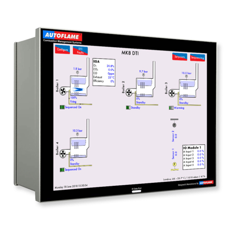
AUTOFLAME Mk7 User manual

M
Mk7
D.T.I.
Set-Up
Guide
Mk7
数据传输接口设置指南


Mk7
D.T.I.
Set-Up
Guide
Mk7
数据传输
接口设置指南
Issued
by 发布公司:
AUTOFLAME
ENGINEERING
LTD
AUTOFLAME 工程有限公司
Unit 1-2,
Concorde Business
C
entre
Airport Industrial
Estate,
WirelessRoad
Biggin
Hill, Kent TN16
3YN
Tel:
+44 (0)845 872
2000
电话:
+44 (0)845 872
2000
Fax: +44 (0)845 872
2010
传真:+44 (0)845 872
2010
Email: [email protected]
电子邮件:
Website:
http://www.autoflame.com/
网站:
http://www.autoflame.com/
Registered
Holder 注册持有人:
Company 公司:
Department 部门:
This
manual and all the information
contained
herein
is copyright
of
Autoflame
Engineering Ltd.
It may not be
copied
in the whole or part without
the
consent
of the Managing
Director.
Autoflame工程有限公司拥有本手册的所有版权。在未经Autoflame公司常务董事同意的情况
下,本手册内容不得被整体或部分引用。
Autoflame
Engineering Ltd’s policy is
one of
continuous
improvement in
both
design
and manufacture. We therefore reserve the right to
a
m
end
specifications
and/pr data without prior
notice.
All details
contained
in
this
manual are
correct
at the time of going to print.
Autoflame工程有限公司致力于不断提升Autoflame产品的设计和制造,我们保留修订本手册
规范/数据的权利,恕不另行通知。本手册内容于付印时准确无误。

Important
Notes
重要说明
A knowledge of
combustion
related
procedures
and
commissioning is essential
before
embarking work on any of the M.M./E.G.A.
systems. This
is for safety reasons and
effective
use
of the
M.M./
E.G.A. system.
Hands on training
is
required. For details on
schedules
and
fees
relating to group training
courses
and individual
instruction,
please
contact
the Autoflame
Engineering Ltd. offices
at the
address listed
on the front.
为了安全有效地使用控制模块/EGA系统,控制模块/EGA系统的操作员必须具有与燃烧相关的流程知
识和调试知识。我们要求操作员参加实践培训,请按首页所述地址联系上Autoflame办公室详细了解
团体培训课程和个别辅导的时间和费用。
Short Form -
General
Terms
and
Conditions
一般条款
A full statement of our
business terms
and
conditions
are printed on the reverse of
all
invoices.
A copyof
these can
be
issued
upon application, if requested in
writing.
所有发票背面均都印有我方商业条款全文。客户可书面申请获取我公司的商业条款文件。
The
System
equipment
and
control
concepts
referred to
in
this
Manual
MUST
beinstalled,
commissioned
and applied by
personnel skilled
in the various
technical disciplines
that
are inherent to the Autoflame
product
range, i.e.
combustion, electrical
and control.
仅有专业人员才能安装、调试、使用本手册所提及的系统设备和控制原理。他们必须精通 Autoflame
产品所涉及的燃烧、电气和控制等技术学科。
The
sale of Autoflame’s
systems
and equipment referred to in
this
Manual
assume
that
the dealer,
purchaser
and installer has the
necessary skills
at
his disposal.
i.e. A high
degree of
combustion
engineering experience, and a thorough understanding of the
local electri
c
al
codes
of
practice concerning boilers, burners
and their ancillary systems
and equipment.
经销商、采购商和安装人员必须具有丰富的燃烧工程从业经验、全面了解当地涉及锅炉、燃烧器和辅
助系统/设备相关的电气行业规范方能使用本手册提及的 Autoflame 系统和设备。
Autoflame’s warranty from point of sale is two years on all
electronic systems
and
components.
Autoflame保修条款: 对所有电子系统和部件实行两年售后保修;
One year on all
mechanical systems, components
and sensors.
对所有机械系统、部件和传感器实行一年售后保修。
The
warranty
assumes
that all equipment supplied will be used for the purpose that
it was intended and in
strict compliance
with our
technical
recommendations.
Auto
-
flame’s warranty and guarantee
is
limited
strictly
to
product
build quality, and design.
Excluded
absolutely are any
claims
arising from
misapplication, incorrect
installation
and/or
incorrect
commissioning.
保修前提: 所有设备均按预期使用目的使用并严格遵守我方提供的的技术建议。Autoflame 产品保修条
款仅适用于产品制造质量问题和设计问题。根据保修条款,Autoflame 不接受因误操作、误安装和/或
调试导致的任何索赔请求。

Contents 目录
1MK7
DATA TRANSFER
I
N
TE
RFACE
MODULE
.
Mk7 数据传输接口模块
. ........ ........... ... ....
1
1
Overview
of
the
Mk7
D.T.I.
Mk7 数据传输接口概述
..... ... ... .... ... ... ... ................
1
1.1.1
Introduction
to
the
Mk7
D.
T.I.
Mk7 数据传输接口简介
.. ... ... ... ...... .... .... ..... ... ... ... ........
1
1.1.2
Information Available from
Mk7
D.T.I.
Mk7 数据传输接口信息
... ... ... .... .... .......
1
1.2
Fixing Holes and
Dimens
ions
.
固定孔和尺寸
....... .... .... .... .... .... .... ..... ... ... ... .........................
4
2
SET-UP
AND
CONNECTIONS
.
设置和连接
................................................................
5
2.1
Wiri
ng
接线
................................................... ... ... .... .... .... ....... ........................
5
2.1.1 Mk7
D.T.I. Wiring
Diag
ram
Mk7 数据传输接口接线图
... ... ... ... ........
5
2.1.2
System Schematic
系统原理图
...... .... .... .... .... .... .... ... ... ... ... .............
6
2.1.3 M.M.
Module
s
Connection
控制模块的连接
. .... .... . .... .... ....... .... .... ..... ... ... ... ...............
7
2.1.4 Mk7 M.M.
and
Mk8
E.G.A. with
Mk7
D.T.I
... .... .... .... .... .... .... .... .... .... .... ... ... ...............
8
MK7 控制模块和带 Mk7 数据传输接口的 Mk8 尾气分析仪
2.2 Mk7
D.T.I. Set-Up
.
Mk7 数据传输接口的设置
.. .... .... .... .... .... .... ..............
9
2.2.1 Mk7 M.M.
Option
s
and
Pa
rame
ters
..
Mk7 控制模块选项和参数
.... .... .... .... .... .... .... .... ...
9
2.2.2 Mini Mk8 M.M.
Options and Parameters
Mk8 微型控制模块选项和参数
. .. ......
12
2.2.3
Configuring the Boiler Room
配置锅炉房
. ... ... ... ... ... .... ... ... .... ... ... .......
15
2.2.4
D.T.I. Setup
数据传输接口的设置
. ... ... .... .... .... ....... ... ... ... ... ....
22
2.2.5
Deleting Boilers and
I/O
Modules.
删除锅炉和输入输出模块
. . .... .... .... ..... .....
25
2.2.6
Network
Set-Up
...
网络设置
...... .... .... .... .... ............ ... ... ... ...............
30
2.3 Mk7
D.T.I. Connections
...
Mk7 数据传输接口的连接
. ... ... ... ... .... .... .... .... ......
32
2.3.1
PC Connection
..
PC 连接
..... .... . ... ... ... ...... .... ......... ... ... ... ..................
32
2.3.2
Network Connection...
网 络 连 接
...... ........ ... ... ...........................
33
2.3.3
Pinging the D.T.I...
Pinging 数据传输接口
.... .... .... .... .... .... ........ ... ... ...........
34
2.3.4
RS422 Connection....
RS422 的连接
.... ... .... .... .... .... .... .... ........ ... ... ... .......................
35
3
ANALOGUE
AND
D
I
G
I
T
A
L
INPUTS/OUTPUTS
.
模 拟 和 数 字 输入 输 出
............
36
3.1 Mk7
Universal
Input/
Output
Mo
du
le
....
Mk7 通用输入输出模块
.....................................
36
3.1.1
Introduction..
简介
..................................................................
36
3.1.2
Wiring and Dimensions...
接线盒尺寸
..............................................
37
3.1.3
Set-Up
I/O
Module
s
on
Mk7
D.T.I.
..
设置 Mk7DTI 上的输入输出模块
...
39
4
MODBUS.
..............................................................................
..........................
48
4.1 M.M.
Read
A
ddre
sses
.
控制模块读取地址
.................... ... ... ....................
48
4.2
E.G.A. Read Addresses
.
尾气分析仪读取地址
.. .... .... .... ... ... ..................
56
4.3 Input/
Output Modules Read Addresses
.
输入输出模块读取地址
.. . .... .... .... .... ...... ... ........
58
4.4
Read/Write
Addresses
.
读取/写入地址
.. ... .... .... .... . ... ... ... ... ...... ... ... ..........
61
4.4.1 M.M.
Read/Write
Addresses
.
控制模块读取/写入地址
. ... ... ... ... .... .... .......
61
4.4.2
Analogue and Digital
I/O
Read/Write
Addresse
s
模拟和数字输入输出读取/写入地址
.
61

4.5
Information, Errors and
Lo
ckouts
信息、错误和锁定
.. ... ... ............ ....... .............
62
4.5.1
Digital Inputs
(1x
Reference)
.
数字输入(1x参考值)
.... ... ... ... ... ....... ........................
62
4.5.2
Analogue Inputs
(3x
References)
模拟输入(3x 参考值)
... .... ... ... ...... ..............
63
4.5.3
Error and Lockout
C
odes
.
错误和锁定代码
........... ....... ... ... ... ... ....... ....................
64
4.5.4
Water Level
.
水位
................. .... .... ... ... ... ... .... .................. ....... ....... .............................
68
5
INTERACTING
WITH
THE
MK7
D.T
.I
.
.
Mk7 数据传输接口的相互作用
......
69
5.1
Burner
Information.
燃烧器信息
................... ........................ ....... ....... ........................
69
5.2 M.M.
Display
Screen
控制模块显示屏幕
..... .... .............. ....... ....... ..........................
71
5.3
Fault Logs.
故 障日志
................ .... .... ...................... ....... ..................
74
5.4 M.M.
I.B.S
Screen.
控制模块 IBS 屏幕
............. ....... ....... ............................
75
5.5
Display Logs
显示日志
............. . ...... .... .... .... .... ............... ....... .....................
76
5.6
E.G.A. Display Screen
尾气分析仪显示屏幕
.. .... ... ... ... ... .... .... .... .... ..... ....... .......................
78
5.7
I.B.S
Information
IBS 信息
..................... .... . ... ... ...... .... .... ................... ....... ....... ........
79
...

1
Mk7
Data TransferInterfáce
Module Mk7
数据传输接口模块
Page
.4
Mk7 D
.T.I.
Set-Up
Guide Mk7
数据传输接口设置指南
10.08.2015
1 MK7
DATA TRANSFER INTERFACE
MODULE
MK7 数据传输接口模块
1 Overview of the Mk7 D.T.I.
Mk7 数据传输接口概述
1.1.1
Introduction
to the Mk7 D.T.I.
Mk7 数据传输接口简介
The Autoflame Data Transfer Interface (D.T.I.) is
the
gateway
for
commun
i
cat
i
o
n
s
between
the M.M.
and E.G.A. range
of
products.
All of
the
M.M.
operational data,
of
up
to
ten M.Ms
in
one location,
can
be
collected
by
the D.T.I. The information gathered is available
for
transmission
to an
external
source
via
RS422
and
Ethernet data links. The data gathered
by
the
Mk7
D.T.I. can
be
collected and
viewed
using
the
included CEMS
Audit
software, which allows
data
collection
over a
Local
Area Network
(LAN),
or
over the
internet.
Autoflame 数据传输接口是控制模块和尾气分析仪间的通信网关间的通信网关。由于一个位置
可以有 10 个控制模块,因此控制模块的所有运行数据都可以通过数据传输接口控制,收集的
信息将通过 RS422 和以太网数据链路传输至外部源。Mk7 数据传输接口收集的数据可以用
CEMS Audit 软件收集、查看,CEMS Audit 软件允许通过局域网或互联网进行数据收集。
Up to a
maximum
of ten M.M.
modules,
can be
connected
to one
D.T.I. module. This
can be a
combination
of Mk7 M.M.
modules
and Mini Mk8 M.M.
modules.
It
is also
pos
s
ible
to
receive
data
from up to 10
E.G.A.s
for
emissions
data.
To accommodate
the
status information
from other plant
related
equipment,
the
D.T.I.
can
communicate
with up to ten Mk6
Analogue
and ten Mk6 Digital
Input/
Output Modules,
or
ten
Mk7
Universal
Input/
Output modules. The information gathered
by the
D.
T
.
I
.
from
each
system
i
s
then available for
transmission
to the
Building Management System
or
Energy Management System (BMS
or
EMS). This is done through the RS422
link or
Ethernet
to send
data via
Modbus communications. Typical remote B.M.S. information
and
operational facilities
are
subject
to
the particular site
and management system
requirements.
一个数据传输接口模块最多可以连接 10 个控制模块,该数据接口模块可以是 Mk7 控制模块和
Mk8 微型控制模块的组合,同时也可以从 10 个尾气分析仪模块接收尾气数据。为适应其他工
厂相关设备的状态信息。该数据传输接口可以与 10 个Mk6 模拟模块和 10 个Mk6 数字输入输
出模块或 10 个Mk7 通用输入输出模块进行通信。数据传输接口从各系统接收的信息可以传输
至楼宇管理系统或能源管理系统,传输将通过 RS422 链路或以太网利用 Modbus 通信完成数
据传输。典型的远程楼宇管理系统信息和运行设施需要满足特定站点和管理系统的要求。
The Autoflame network operates using
a two
core screened cable
and
features dedicated
data ports
for
RS422
and
Ethernet connections. The
Mk7
D.T.I. poles
each item on the
network
periodically,
storing up-to-date information every
2
seconds. The D.T.I. then outputs
to
defined Modbus
a
ddresses,
which
are then available to third party
systems
like a
B.M.S. The
10.4”
touch-screen displays
the
operational status
of
the D.T.I.’s communications, with corresponding
error
conditions
in
the event
of a
communication
failure.
Autoflame 网络使用一个双芯屏蔽电缆运行,配有 RS422 和以太网连接的专用数据接口。Mk7
数据传输接口定期在网络上轮询各项目,每两秒储存一次更新信息。然后数据传输接口输出至
指定的 Modbus 地址,Modbus 地址则分配给第三方系统如楼宇管理系统。10.4”触摸屏用于显
示数据传输接口的通信运行状态,出现通信故障时将提供相应的错误条件。
1.1.2 Information Available from Mk7 D.T.I.
Mk7 数据传输接口信息
The
Mk7
D.T.I. displays information from the
Mk7 M.M., Mini Mk8 M.M., Mk8
E.G.A., and the
Water
Level control. Remote
on/off
control
of
the burners can also
be
achieved as
well
as the adjustment
of
the temperature
or
pressure setpoints
and
the sequence order. Through the D.T.I. touch screen, CEMS

1
Mk7
Data TransferInterfáce
Module Mk7
数据传输接口模块
Page
.4
Mk7 D
.T.I.
Set-Up
Guide Mk7
数据传输接口设置指南
10.08.2015
Audit software and via Modbus, the following information is
available:
Mk7 数据传输接口显示 Mk7 控制模块、Mk8 微型控制模块、Mk8 尾气分析仪和水位控制信
息。燃烧器可以进行远程开启/关闭控制,同时还可以远程调节温度或压力设定值和排列顺序。
通过数据传输接口触摸屏、CEMS Audit 软件和 Modbus 可以显示以下信息:
Mk7
D.T.I. Input Values
Mk7
数据传输接口输入值
Enable/disable burner
启用
/
禁用燃烧器
Change individual required setpoint
更改单个需要的设定值
Change global required setpoint
更改全局需要的设定值
Selectlead
boiler
选择主锅炉
Shuffle sequencing (not
M
o
dbus)
重新排序(非 Modbus)
Set load index (firing
rate)
设置负荷指标(燃烧率)
Label
and control input/outputs (not Modbus)
标志并控制输入输出(非 Modbus)
Mk7 M.M.
Mk7 控制模块
Actual boiler temperature (deg. C/F)
or
pressure
(Bar/PSI)
锅炉实际温度(C/F)或压力(Bar/PSI)
Required setpoint i.e. required boiler temperature (deg. C/F)
or
pressure
(Bar/PSI)
所需设定值如所需锅炉温度(C/F)或压力(Bar/PSI)
Burner
on/off
status
燃烧器启停状态
Burner firing rate
(%)
燃烧器燃烧率(%)
Fuel selected
选定的燃油
Burner
rating
燃烧器额定值
Fuelflow metering
values
燃油流量计量值
Load detector type
(temperature/pressure)
负荷检测器类型(温度/压力)
16
lockout and error history with date and
conditions
16 个锁定和错误历史,带数据和条件
Auto/hand/low
flame hold
operation
自动/手动/低火焰保持操作
Number
of
channels
used
使用的通道数量
Channe1,
2, 3, 4, 7,
servomotor
angle
通道 1,2,3,4,7 伺服电机角度
Channel
5, 6
output and input signals
to
VFDwith feedback
history
通道 5,6 至VFD的输入输出信号,带反馈历史。
Burner firing status phase (off, standby, purge, ignition, firing
etc.)
燃烧器燃烧状态阶段(关闭、待机、吹扫、点火、燃烧等)
Lead/lag boiler status
主从锅炉状态
Sequence
order
排序顺序

1
Mk7
Data TransferInterfáce
Module Mk7
数据传输接口模块
Page
.4
Mk7 D
.T.I.
Set-Up
Guide Mk7
数据传输接口设置指南
10.08.2015
Sequence status (on, standby warming,
off)
排序状态(开启、待机、警告、关闭)
Enabled/disabled status
启用/禁用状态
Total hours
run
总运行时间
Number
of
start-ups per
fuel
每次燃油启动次数
Online and commissioned
gas/ oil pressure
在线和调试的燃气/燃油压力
Online and commissioned
air pressure
在线和调试的空气压力
UV scannersignal
history
紫外线扫描仪信号历史
Mk8 E.G.A.
Mk8 尾气分析仪
E.G.A. operation
optioned
选定的尾气分析仪操作
Standalone/M.M.
operation
独立操作/控制模块操作
Flue gas
O2
present
value
油气中 O2现值
Flue gas
CO2
present
value
油气中 CO2现值
Flue gas CO present
value
油气中 CO 现值
Flue gas
NO
present
value
油气中 NO 现值
Flue gas
NO2
present value
(if optioned)
油气中 NO2现值(如选择)
Flue gas
SO2
present value
(if optioned)
油气中 SO2现值(如选择)
Flue gas
O2
commissioned
value
油气中 O2调试值
Flue gas
CO2
commissioned
value
油气中 CO2调试值
Flue gas CO commissioned
value
油气中 CO 调试值
Flue gas
NO
commissioned
value
油气中 NO 调试值
Flue gas
NO2
commissioned value
(if optioned)
油气中 NO2 调试值(如选择)
Flue gas
SO2
commissioned value
(if optioned)
油气中 SO2 调试值(如选择)
Flue gas exhaust
temperature
油气排气温度
Ambient
temperature
环境温度
Flue gas delta
temperature
油气 delta 温度
E.G.A.
errors
尾气分析仪故障
Chiller
condition
冷却器条件
Current emissions
byweight
and volume
(O2,
CO
2
, CO,
NO,
SO
3
, H
2
O,
N2, Total)
当前尾气重量和体积(O2,
CO
2
, CO,
NO,
SO
3
, H
2
O,
N2, 总计)
Totalised emissions
by
weight and volume
(O2,
CO
2
, CO,
NO,
SO
3
, H
2
O,
N2, Total)

1
Mk7
Data TransferInterfáce
Module Mk7
数据传输接口模块
Page
.4
Mk7 D
.T.I.
Set-Up
Guide Mk7
数据传输接口设置指南
10.08.2015
总尾气重量和体积(O2,
CO
2
, CO,
NO,
SO
3
, H
2
O,
N2,总计)
Heat input, heat loss and net useful
heat
热输入、热损失和净用热
Net efficiency, gross efficiency and delta
temperature
净效率、总效率和 delta温度
Fuelflow rates, instantaneo
u
s
and
total
i
s
e
d
for
up
to2 years
两年内燃油流量,瞬时和总计
Fuel consumption, fuel costs instantaneous and totalise
for
up
2 years
两年内燃油消耗、燃油费用,瞬时和总计
MiniMk 8 M.M. M
Mk8 微型控制模块
Actual boiler temperature (deg. C/F)
or
pressure
(Bar/PSI)
锅炉实际温度(C/F)或压力(Bar/PSI)
Required setpoint i.e. required boiler temperature (deg. C/F)
or
pressure
(Bar/PSI)
所需设定值如所需锅炉温度(C/F)或压力(Bar/PSI)
Burner
on/off
status
燃烧器启停状态
Burner firing rate
(%)
燃烧器燃烧率(%)
Fuel
selected
选定的燃油
Burner
rating
燃烧器额定值
Fuelflow metering
values
燃油流量计量值
Load detector type
(temperature/pressure)
负荷检测器类型(温度/压力)
16
lockout and error history with date and
conditions
16 个锁定和错误历史,带数据和条件
Auto/hand/low
flame hold
operation
自动/手动/低火焰保持操作
Number
of
channels
used
使用的通道数量
Channe1,
2, 3, 4, 7,
servomotor
angle
通道 1,2,3,4,7 伺服电机角度
Channel
5, 6
output and input signals
to
VFDwith feedback
history
通道 5,6 至VFD的输入输出信号,带反馈历史。
Burner firing status phase (off, standby, purge, ignition, firing
etc.)
燃烧器燃烧状态阶段(关闭、待机、吹扫、点火、燃烧等)
Lead/lag boiler status
主从锅炉状态
Sequence
order
排序顺序
Sequence status (on, standby warming,
off)
排序状态(开启、待机、警告、关闭)
Enabled/disabled status
启用/禁用状态
Total hours
run
总运行时间
Number
of
start-ups per
fuel
每次燃油启动次数
Water Level
Control
水位控制
Actual water level signal value
for
probe
1
and
2
探头 1和2实际水位信号值

1
Mk7
Data TransferInterfáce
Module Mk7
数据传输接口模块
Page
.4
Mk7 D
.T.I.
Set-Up
Guide Mk7
数据传输接口设置指南
10.08.2015
Average water level signal
of probes
探头的平均水位信号
Commissioned end
of
probe
position
探头位置的调试端
Commissioned
2nd lowposition
调试的第二低位
Commissioned 1
st
lowposition
调试的第一低位
Commissioned 1
st
low
pre-alarm
position
各报警位置的调试第一低位
Commissioned control point
position
调试控制点位置
Commissioned pump
on/
pump
offpositions
调试的泵启停位置
Commissioned high water pre-alarm
position
各报警位置的调试高水位
Commissioned high water
position
调试的高水位位置
15
Firstout annunciation inputs status
15 个点火控制器输入状态
Instantaneous and totalised steamflow
m
e
tering
瞬时和总计蒸汽流量计量
Feedwater
temperature
给水温度
Feedwater valve
position
给水阀位置
Feedwater pump status
给水泵状态
Feedwater VSD
output
给水 VSD 输出
Steam temperature and
pressure
蒸汽温度和压力
Top blow down status and
operation
顶吹状态及操作
TDSactual
value
TDS 实际位置
TDSvalve
position
TDS 阀位置
TDS target
value
TDS 目标值
16
Water
level/
Expansion alarms conditions and
date
16 个水位/扩展报警条件和日期
Bottom blowdown
operation
底部排污操作

1
Mk7
Data TransferInterfáce
Module Mk7
数据传输接口模块
Page
.4
Mk7 D
.T.I.
Set-Up
Guide Mk7
数据传输接口设置指南
10.08.2015
1.2
Fixing Holesand Dimensions
固定孔和尺寸

2
Set-Up
and Connections
设置和连接
10.08.2015
Mk7
D.T.I. Set-Up
GuideMk7 数据传输接口设置指南
Page
5
2
SET-UP
AND CONNECTIONS 设置和连接
2.1 Wiring 接线
2.1.1 Mk7 D.T.I.Wiring Diagram MK7 数据传输接口接线图
Figure 2.1.1.i
Mk7
D.T.I.
Wiring Diagram
图
2.
1.1.iMk7
数据传输接口接线图
Electrical
Spe
c
ific
atio
ns:
电气规范
Max
power
for
the
Mk7
D.T.I. power supply is
184W.
Mk7 数据传输接口电源的最大功率是 184W。
Figure
2.1.1.iiMk7
D.T.I.
Board
图
2.1.1.ii Mk7
数据传输接口板

2
Set-Up
and Connections
设置和连接
Mk7
D
.
T.
I.
Set-Up
GuideMk7
数据传输接口设置指南
10.08.2015
Page
6
2.1.2 System Schematic
系统原理图

2
Set-Up
and Connections
设置和连接
10.08.2015
Mk7
D.T.I. Set-Up
Guide Mk7 数据传输接口设置指南
Page
7
2.1.3 M.M. ModulesConnection
控制模块的连接

2
Set-Up
and Connections
设置和连接
Page
8
Mk7
D.T.I. Set-Up
Guide Mk7 数据传输接口设置指南
10.08.2015
2.1.4 Mk7 M.M. and Mk8
E.G.A.
with Mk7 D.T.I.
MK7 控制模块和带 Mk7 数据传输接口的 Mk8 尾气分析仪

2
Set-Up
and Connections
设置和连接
10.08.2015
Mk7
D.T.I. Set-Up
Guide Mk7 数据传输接口设置指南
Page
9
2.2 Mk7 D.T.I.Set-Up Mk7 数据传输接口的设置
2.2.1 Mk7 M.M.
Options
and Parameters Mk7 控制模块选项和参数
To get the
Mk7
D.T.I.
to
communicate with the
Mk7M.M.,
the right communication settings need
tobe
set on the
Mk7 M.M.
The
following options and parameters need
to
be set.
要使 Mk7 数据传输接口和 Mk7 控制模块保持通信,需要在 Mk7 控制模块上进行正确的通信设
置,需要设置以下选项和参数:

2
Set-Up
and Connections
设置和连接
Page
10
Mk7
D.T.I. Set-Up
Guide Mk7 数据传输接口设置指南
10.08.2015
3 0
DTI Comms
Mode
数据传输接口命令模式
0 Mk6
DTI -
9600bps Mk6 数据传输接口
-
9600bps
1 Mk7
DTI -
19200bps Mk7 数据传输接口
- -
19200bps
16 0 Lead/Lag
(IBS)
and
DTI:
A
lead boiler can
be
selected
by
connecting
a
line voltage
to
terminal
88 on
the appropriate
MM. Only1 MM
may
be
selected as lead boiler
at a
time,
or
the sequencing
will
not operate. The lead boiler can
be
selected
via
the DTI. However,
for
this
tobe
effective
all
the
MM
units on the system must have Terminal
88
volt free. Line voltage on Terminal
88
overrides the DTI
command.
主从(IBS)和数据传输接口:主锅炉可以通过连接线压至相应的控制模块终端 88 进行选
择。一次仅能选择 1个控制模块作为主锅炉,否则排序将不会运行。主锅炉可以通过数据传
输接口选择。因此,为使其生效,系统上的所有控制模块单元上的终端 88 都必须无电压。终
端88 上的线电压将取代数据传输接口命令。
0 No
sequencing
-
MM
units still communicate and can
be
seen on the
DTI.
无排序-控制模块单元仍然通信并可以在数据传输接口上看到。
1
Sequencing enabled
-
MM
units
will
respond
to
sequencing commands. Lead boiler is selected
by a line
voltage on terminal
88.
启用排序-控制模块单元将响应排序命令。主锅炉通过终端 88 上的线压选定。
2
Setpoint
&
enable/disable
commands accepted from
DTI.
可以通过数据传输接口接受设定值和启用/禁用命令。
3
Both
1
and
2. 1和2
Note:
Accurate fuel flow metering must
be
entered
for
sequencing
to
operate. An RS485
datacable
(Belden
9501)
must
be
connected between each
MM
unit (see section
2.17.3.4 for
correct
connection).
注:精确的燃油流量计量必须输入进行排序操作。
RS485
数据电缆(
Belden
9501
)必须连接每个控制模块单
元(见
2.17.3.4
节关于正确连接)。
30 50
DTI
Required Setpoint Minimum
Limit:
If
the system is being used with
a
DTI
a
maximum
and
minimum limit
for
the required setpoint must
be
set.
If a
value is received from the DTI that is
outside
these limits,
it will be
ignored and the system uses its previous required setpoint. Practical range is
limited
to
range
of
sensor
selected. 数据传输接口所需设定值的最小限值:如果系统用于一个
数据传输接口,则需要为所需设定值设定一个最大和最小限值。如果数据传输接口接收的数
值超过该限值,该数值将被忽略,系统将使用先前所需的设定值。实际范围受到所选传感器
范围的限制。
5
-
9990 If
Centigrade, Fahrenheit
or
PSI units
effective. 如是摄氏度,华氏度或 PSI 单位有效。
0.5
-
999.0 If
Bar units effective.
如巴单位有效。
31 100
DTI
Required Setpoint Maximum Limit: 数据传输接口所需设定值的最大限值
5
-
9990 If
Centigrade, Fahrenheit
or
PSI units
effective. 如是摄氏度,华氏度或 PSI 单位有效。
0.5
-
999.0 If
Bar units effective.
如巴单位有效
33 1 MM Identification:
The identification number must
be
set on
all MM
Units
in
the boiler house.
If
not, then problems
will
occur with sequencing/twin burner and with the
DTI communications. Each
unit must have
a
different identification
number.
控制模块标识:标识号必须在锅炉房内所有控制模块单元上设置,如未设置,则燃烧器测
序燃烧器和双燃烧器以及数据传输接口通信将出现问题。各单元必须有不同的标识号。
34 5 Rating of Burner: 燃烧器额定值
1
-
999
See Option
77 for
units.
关于单位见选项
77
77 0 Burner rating
units:
Display purposes only
for
fuel
flowmetering.
燃烧器额定值单位:仅显示燃油流量计量值
0 KW x 100
/hr
1
Kg
x 100
/hr
2 MW
/hr
3
Btu
x 100
/hr
4
Hp
x 100
/hr
5
lbs
x 100
/hr
6
Btu
x 1000
/hr
7
Hp
x 10
/hr
8
lbs
x 1000
/hr
9
Btu
x 1000 000
/hr

2
Set-Up
and Connections
设置和连接
10.08.2015
Mk7
D.T.I. Set-Up
Guide Mk7 数据传输接口设置指南
Page
11
57 0 0
-
10
Sequencing:
Highest
MM
ID. This
parameter speeds up communications between
MM's
when
sequening.
排序:最大控制模块 ID。排序时本参数将加快控制模块间的通信
101 0 Shufflesequencing: 改变排序
0 Disabled 禁用
1
Sequence order changed from
DTI.
排序顺序从数据传输接口改变

2
Set-Up
and Connections
设置和连接
Page
12
Mk7
D.T.I. Set-Up
Guide Mk7 数据传输接口设置指南
10.08.2015
2.2.2 Mini Mk8 M.M. Option
s
and Parameters Mk8 微型控制模块选项和参数
To get the
Mk7
D.T.I.
to
communicate with the
Mini Mk8 M.M.,
the right communication settings
need
to
be seton the
MiniMk8M.M.
The
following options and parameters need
to
be set.
传输接口与 Mk8 微型控制模块保持通信,则需要在 Mk8 微型控制模块进行正确的通信设置。需
要设置以下选项和参数。
Other manuals for Mk7
3
Table of contents
Other AUTOFLAME Measuring Instrument manuals
