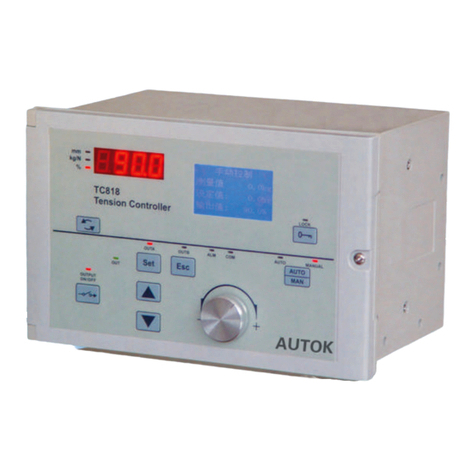
AUTOK TC808 User manual

TENSION CONTROLLER
TC808
INSTRUCTION MANUAL
AUTOK
AUTOK

Table of Contents
Tension sensor
TC808
Tension controller
Magnetic powder brake
Typical installation of an unwind application
TENSION CONTROLLER TC808
1 Introduction ................................................................................. 1
2 Features ....................................................................................... 1
3 Order Code .................................................................................. 2
4 Installation ................................................................................... 2
5 Electrical Wiring .......................................................................... 3
6 Operator Interface ....................................................................... 6
7 Operation ..................................................................................... 7
8 Operation of Tension Control System .................................... 10
9 Tension Calibration .................................................................. 13
10 Use of Diameter Tension Control ........................................... 15
11 Taper Tension Control ............................................................. 17
12 Diameter-Output Program Tension Control .......................... 18
13 Digital Communication ........................................................... 20
Appendix A: ASCII Table .............................................................. 24
Appendix B: The Mounting of SUP Tension Sensor ................. 24
Technical Data .............................................................................. 25
AUTOK
WWW.CHINA-AUTOK.COM

1 Introduction
2 Features
1
TENSION CONTROLLER TC808
● Full digital circuit, easy tension calibration. ● Advanced PID control algorithm provide high
control precision.
● Universal tension sensor input:
● RS485/RS232 serial communications.
1. Micro-displacment based tension sensor
(signal: 200mV, power supply:5V) ● Tension transmission.
2. Strain gauge based tension sensor ● Automatic/Manual tension control.
(signal:20mV,power supply10V) ● Reel exchange function.
● Diameter tension control.
● Wild range switching power supply(85~264V).
● Taper tension control.
● Friendly user interface, easy to use.
● Program tension control, multi programs for ● More cost efficient.
various material tension control.
The TC808 Tension Controller is an application-specific controller designed to provide you with precise
control over winding and unwinding tension control applications for web and strand.
The tension controllers can be divided into manual, half-automatic and full automatic controller. According to
the different needs of customers, the TC808 tension controller can be configured as manual, half-automatic
or full-automatic tension controller.
For manual tension controller, the operator adjusts the actuation current of the powder clutch/brake manually
to get the desired tension control.
The half-automatic tension controller also known as diameter or opened-loop tension controller, the tension
controller calculates the reel radius automatically during winding or unwinding process, according to the
current reel radius and setting tension, the tension controller adjusts the output to get the constant tension
controls.
The full automatic tension controllers detect the web tension with tension sensor directly. According to the
difference between setting tension and measured tension and the build-in PID algorithm, the controller
adjusts the output automatically to get the precision constant tension control of the web.
AUTOK
WWW.CHINA-AUTOK.COM

TC808 tension controller can be installed on floor, wall or panel.
MAN
AUT O
PAR PROG
OFF ON
POW ER
AUT O MAN
OUT B OUTA ALM C OM
OUT
PV
SV
TC808
TENSI ON CONTROL LER
OUT PUT
ON/ OFF
N
%
R
MON ITOR
SEL ECT
256
168
Installed on floor
172.5
Installed on wall
4-M4*12
Mounting screw
2~4 140
Installed on panel
4-M4
244 +3
-0.5
80+
-
0.5
Screw holes dimensions
for mounting on floor and wall
232
+
-
0.5
150+
-
0.5
Output
24V
Model Number
TC808
-
-
Comms
0
RS232
RS485
BS
Options
0
QP
Tension Controller
Comments
24V/4A
Drive powder clutch/brake
None
RS232
RS485
Tension transmission
None
Programmer/Controller
4 Installation
3 Order Code
Panel mounting cut-out dimensions
TENSION CONTROLLER TC808
2
AUTOK
AUTOK
WWW.CHINA-AUTOK.COM

MAN
AUTO
PAR PROG
OFF ON
POWER
AUTO MAN
OUTB OUTA ALM COM
OUT
PV
SV
TC808
TENSION CONTROLLER
OUT PUT
ON/ OFF
N
%
R
MONITO R
SELECT
245
228
16.5 140
147
154
60
60
5 Electrical Wiring
Notice
TENSION CONTROLLER TC808
Outline Dimensions
3
●
line.
● If the AC power supply is connected to the I/O terminals or DC supply terminals, the tension controller will
be burn out.
● Connect the tension sensor according to the wiring diagram, pay more attention to the wiring of tension
sensor if two tension sensors are connected otherwise the measurement value will be incorrect.
● When one tension sensor is used, make sure to short-circuit the unused tension signal terminals.
In order to avoid electrical noise to the input signal, the signal line should be seqarated from the power
AUTOK
AUTOK
WWW.CHINA-AUTOK.COM

RY
NB
PB
NA
PA
12V/2A
24V/4A
-5V
5V
Main reel pulse
Auxiliary power output
Communications
or
Tension transmission
Acceleration switch
Dot start
Start output select
Deceleration switch
Reel exchange
Output 2
4 ~ 20 mA
Zero tension
alarm output
Power supply
(160V~240 V AC)
24V
DI0
DIA
DIB
GND
MC6
MC5
MC4
MC3
MC2
MC1
MCC 0V
+6V
TRG
TR-
TR+
ZT
ZT
EAP
EAN
SA
Run/Stop
SN
{
}
}
}
}
}
250V 8A
PSL
PSN
REDL
GRL
WHL
GRR
WHR
BLKL
REDR
BLKR
Tension
sensor
(Left)
A/D
A/D
Terminals Layout
Terminal group 1 Terminal group 2
PSL PSN ZTC NA NB MCC MC2 MC4 MC6 DI0
+24V
GNDMC5
MC3
MC1PBPAZTZT DIB WHL BLKL BLKR WHR SA EAP TRG TR+
DIA GRL REDL REDR SN EAN +6V 0V TR-GRR
5.1 Wiring Diagram
Tension
sensor
(Right)
red
green
white
black
red
green
white
black
0 ~ 20 mA
Sync signal output
to Reel-A magnetic
powder clutch/brake
to Reel-B magnetic
powder clutch/brake
Reel-A pulse
Reel-B pulse
Power board
TENSION CONTROLLER TC808
4
AUTOK
WWW.CHINA-AUTOK.COM

5.2 Terminals Description
Terminal group 1
SN
1
2
3
4
5
6
7
8
9
10
11
12
13
Terminal
PSL, PSN
ZT, ZTC
PA NA,
PB, NB
MCC
MC1
MC2
MC3
MC4
MC5
MC6
+24V, GND
DI0
Specification Comments
input
output
output
output
input
input
input
input
input
input
input
input
output
85~264V AC, 50/60 Hz
I/O
Power supply
Zero tension alarm output(Automatic tension control mode)
Reel radius lower limit alarm output(Diameter tension
control mode)
Output for reel A powder clutch/brake, motor
Output for reel B powder clutch/brake, motor
Contact input common terminal
Run/stop
Reel exchange signal
Acceleration switch
Start output selection
Dot start signal input
Deceleration switch
Power supply of proximity switch or encoder
Main reel pulse inputMax Freq: 15K Hz
24V/4A or 90V/10A
24V/4A or 90V/10A
1
2
3
4
5
6
7
8
9
10
11
12
13
DIA
DIB
GRL
WHL
REDL
BLKL
GRR
WHR
REDR
BLKR
SA SN,
EAP,EAN
TR+,TR-,TRG
input
input
input
input
output
output
input
input
output
output
output
output
output
Max freq: 15K Hz Reel A pulse input
Reel B pulse input
Left tension sensor signal+
Left tension sensor signal-
Left tension sensor power supply+
Left tension sensor power supply-
Right tension sensor signal+
Right tension sensor signal-
Right tension sensor power supply+
Right tension sensor power supply-
Control signal output
Control signal output for E/P regulator
Serial communication or tension transmission
RS232/RS485
0~200mV or 0~20mV
14 +6V,0V output Auxiliary power supply
Max freq: 15K Hz
5V or 12V
0~200mV or 0~20mV
5V or 12V
0~20mA or 0~5V
0~20mA or 0~5V
SN Terminal Specification CommentsI/O
Terminal group 2
TENSION CONTROLLER TC808
5
AUTOK
WWW.CHINA-AUTOK.COM

DescriptionSN Item
6 Operator Interface
TENSION CONTROLLER TC808
6
PV Display Indicates the Process Value,
Parameter display
Indicates the Setting Value,
parameter value, alarm code
Tension SV displaying LED
Output power displaying LED
SN Item Description
SV Display
Reel radius displaying LED
N
%
R
Lower display selector
Automatic mode indicator
Manual mode indicator
AUTO
MAN
Manual/Automatic mode
switching key
Parameter scroll key
Raise key, increase value
Programming key
Lower key, decrease value
Power switch
ON/OFF
Power LED
Output power indicator
higher the output, brighter the
LED
Reel B output indicator
Reel A output indicator
Zero tension alarm indicator
Communication indicator
Output ON/OFF switch
Output ON/OFF LED
lit when output is ‘ON’
POWER
OUT
OUTB
OUTA
ALM
COM
PAR
PROG
MONITOR
SELECT
MAN
AUTO
OUTPUT
ON/OFF
1
3
2
4
5
6
7
8
9
10
11
12
PAR PROG
OFF ON
POWER
OUTB OUTA ALM COM
OUT
PV
SV
TC808
TENSION CONTROLLER
OUTPUT
ON/OFF
8
9
10
11
12
MAN
AUTO
AUTO MAN
N
%
R
MONITOR
SELECT
1
3
2
4
5
6
7
AUTOK
AUTOK
WWW.CHINA-AUTOK.COM

7 Operation
TENSION CONTROLLER TC808
7
There are two LED displays indicate the operating parameters.
The upper display(green) indicates the measured tension value(PV) when in base condition. On modifying a
parameter, the appropriate parameter appears.
The Lower display(red) indicates the setting tension value in the automatic mode. On modifying a parameter,
the appropriate value appears here. This display also indicates the output power, reel diameter in some
case.
When the controller is powered on, the upper display indicates the model code of the controller, and the
lower display indicates the software version.
3 seconds later, the upper display will indicates the measured tension(PV) while the lower display will
indicates the setting tension(SV).
The upper display will indicates the current measured reel radius when TC808 is configured as a 'Diameter
Tension Controllr' or a 'Diameter-Output program tension controller'.
The type of contents displayed on the lower display is changed every time the ‘Lower display selector’ key is
pressed. The type of contents displayed is indicated by the LED provided on the left side of the ‘Lower
display selector’ key.
When running in Diameter-Output program tension control mode and the indicator ‘N’ is lit, the lower display
will indicates the program number and segment number of the current running program. e.g. ‘L2.R3’ represent
Program 2 segment 3 is running.
Press Man/Auto key, automatic operation mode and manual operation mode can be changed conveniently.
When TC808 performs automatic operation, indicator ‘AUTO’ will be lit, if the setting tension is displaying on
the lower display at this time(LED ‘N’ is lit) press keys and to modify the setting tension. Adjustable
range: SP K~SP L.
When the controller performs manual operation, indicator ‘MAN’ will be lit, if output power is displaying on the
lower display at this time(LED ‘%’ is lit) the control output power can be modified by pressing and key.
Control output power can be turned ON and OFF by pressing ‘OUTPUT ON/OFF’ key. When indicator
‘OUTPUT ON/OFF’ is lit, output is ‘ON’ otherwise output is ‘OFF’, the output power becomes 0.
In automatic operation mode and when MC1 switch is turned on, indicator ‘OUTPUT ON/OFF’ will be lit;
when MC1 switch is turned off, indicator ‘OUTPUT ON/OFF’ will flash, at this time the output is permissive.
The green LED ‘OUT’ indicates the current control output level, higher the output power level, brighter the
LED. The LED will be turned off when the output becomes 0.
LED ‘OUTA’ indicates the output status of Reel-A, it is lit when Reel-A output is ON.
LED ‘OUTB’ indicates the output status of Reel-B, it is lit when Reel-B output is ON.
When measured tension is lower than ‘zero tension alarm value’(Code AL0), zero tension alarm indicator
‘ALM’ will be lit and at the same time relay ZT is ‘ON’, generate a alarm signal. Zero tension alarm don’t act
in Run/Stop and reel exchange progress.
The indicator 'COM' flashed when the TC808 is in active communication with a host computer.
▲ ▼
▲ ▼
7.1 Display & Basic Operation
AUTOK
WWW.CHINA-AUTOK.COM

Specific tension contol systems need specific software configurations. TC808 must be configured porperly in
order to perform the correct control funtion.
How to enter software configuration menu:
1) Press PAR key and hold for 3 seconds to enter the first level menu(i.e. operation parameter list);
2) Press PAR key to scroll the parameter to LOC and set its value to
3) Press PAR key, the first parameter appears on the upper display, at the same time the lower display will
display the value of this parameter. The values can be modified by pressing keys ▲ and ▼ . After
modification, press the PAR key, the next parameter appears, at the same time, the modified data has been
saved in the memory.
If the last parameter is displayed or there is no key operation within 16 seconds, the controller will return
back to the PV/SV display status.
After configuration, set the configuration password(code LOC) to data other than 808 in order to protect the
parameter values from being inadvertent modification.
808(the initial password);
TENSION CONTROLLER TC808
8
Mnemonic
AL0
TON
POFF
TOFF
PROP
INT.T
PDOT
DB
PCHA
REL.C
TCHA
STOP
( ,NC
(DEC
LOC
PON
SN
4
5
6
7
8
9
10
13
11
14
12
15
16
17
18
19
Parameter
Zero tension alarm value
Start output value
Start time
Stop output value
Stop time
Proportional band
Integral time
Dot start output
Dead band
Reel exchange output
Dead band ratio
Reel exchange time
Reel exchange brake time
Acceleration coefficient
Deceleration coefficient
Configuration password
Adjustable Range
0.0~999.9 Kg
0~100.0%
1~30.0 seconds
0~100.0%
1~30.0 seconds
0.1~999.9 Kg
1~100 seconds
1~100%
0.1~999.9Kg
1~100%
0.01~1.00
1~30.0 seconds
1~30.0 seconds
0.01~0.99
1.00~1.99
0~9999
Comments
Only alarms while running
when MC4 & MCC are shorted, start output value is PON
The smaller the PROP the faster response
The greater the PROP, the slower response
,
The smaller the INT.T, the faster response
The greater the INT.T, the slower response
set to 808 to enter the configuration menu
Operation Parameter List
F0
3 Start frequency 1~50 Hz If main reel freq. F > F0, system starts
If main reel freq. F < F0, system stops
7.2 Modifying the Operation Parameter
7.3 Software Configuration
R0
1 Initial reel radius 0~1000mm
TH,N
2 Material thickness 0.00~3.00mm
When the controller is in the PV/SV displaying status, press PAR key and hold for 3 seconds reveals the first
parameter. The parameter value can either be modified with the or key, or left unmodified. Press PAR
key again, the next parameter and its current value appears, the modified data has been saved.
or there’s no key operation within 16 seconds, the menu times out
automatically.
▲ ▼
If the last parameter is displayed
In dead band, the smaller REL.C, the smaller
proportional gain, this made the system more
stable but slower response.
AUTOK
WWW.CHINA-AUTOK.COM

SN
1
2
3
5
6
7
8
9
14
10
11
12
13
15
16
17
18
19
20
21
23
24
27
28
Mnemonic Parameter Adjustable Range Comments
SP K
SP L
K PL
0FST
SN
ADDR
BAVD
FVNC
(AL(
(TRL
T 1
K, R
LO R
N1
N2
R1
TT
RAL
((
RVN
0P2
PL-2
F,L
(AL
Tension setpoint high limit
Tension setpoint low limit
Max output power
Input/calibration offset
Display units of input signal
Instrument address
Baud rate
Control Function
Reel radius calculation
Control algorithm
Taper ratio
Reel radius high limit
Reel radius low limit
P revolution
(main reel)
ulses/
Pulses/revolution
(Reel-A or Reel-B)
Main reel radius
Reel pulses/calculation
( calculation radius)
Reel radius lower limit alarm value
Powder brake rated torque
Wind mode
OVT2 output mode
2nd output value
Input filter
Tension calibration
Measurement Range
Measurement Range
0.0~100.0%
-9.99~10.00
TC
.TC
00~99
2400, 4800 9600 19.2, ,
AVTO
D ,A
PR1
PR2
P,D
R SP
RO
P 9
0.01~1.00
1~999 mm
1~999 mm
1~300
1~300
20~500mm
10~3000
1~999mm
1~600NM
VTVN
TVN
AVTO
KAND
0.01~99.99
P 1
P2
without tenths’ precision
with tenths’ precision
Automatic tension control
Diameter tension control
Thickness adding up caculation
Ratio calculation
Appears if (TRL = R SP
or FVNC = D,A
When pulses equal to TT, do a reel
radius calculation.
zero tension calibration
full-scale tension calibration
appears if 0P2 KAND=
same with main output OP1
Manual setting
unwinding(reel radius decrement)
winding(reel radius increment)
Appears if FVNC = D ,A
Appears if (TRL = R SP
0.0~100.0%
PID control
Taper tension control
Program tension control
22 OVT2 Output 2 0-20
4-20
0~20 mA
4~20 mA
25 ACT Control action REV
DIR
reverse control
direct control
26 SYNT Synchronous Run/Stop NO
YES
Disable
Enable
TENSION CONTROLLER TC808
9
Software Configuration Paramter List
always > SP L
always < SP K
4SN.N Tension sensor selection
L-SN
R-SN
L-R
select left tension sensor
select right tension sensor
select left & right tension sensors
AUTOK
WWW.CHINA-AUTOK.COM

TENSION CONTROLLER TC808
10
Starting procedure: Before starting, TC808 will outputs PON to generate preparatory tension. When the
Run/Stop switch(MC1-MCC) is turned on and after a overflow of time set in start timer TON, the automatic
control will start. At this time, indicator ‘OUTPUT ON/OFF’ will be lit. See the figure above.
Stopping procedure: When the Run/Stop switch is turned off, the controller output stop power
until the stop timer times up. After that, controller outputs PON to generate preparatory tension. At this time, indicator
‘OUTPUT ON/OFF’ will be turned off. See the figure above.
When ‘Synchronous Run/Stop’ function is available(SYNT = YES), the run/stop operation is controlled by the frequency of
main reel but not the MC1 input. A proximity switch must be mounted on the main reel before using ‘Synchronous
Run/Stop’ function, the controller will monitor the running frequency of main reel.
When the Run/Stop switch is turned on and main reel freq. is greater than start freq. F0, system starts, indicator
‘OUTPUT ON/OFF’ will be lit.
When the Run/Stop switch is turned on and main reel freq. is smaller than start freq. F0, system stops, the indicator
‘OUT’ ON/OFF will flash.
In full automatic tension control systems, generally short-circuit MC1 and MCC, the system will run/stop according to the
main reel’s frequency automatically. TC808 don’t act run/stop operation during reel exchange process.
Note that when the controller was configured as Diameter Tension Controller(FVNC = D,A), the start timer TON must be
long enough allowed the controller to have enough time to calculate out the reel radius otherwise the controller will
perform incorrectly.
POFF instantly
The system start output selection is controlled by the start output selection switch(MC4-MCC). When the switch is turned
on, start output is PON saved in controller memory. When the switch is turned off, the start output is the output when
system stops.
8.1 Run/Stop
Speed
Control output
OFF
ON
Stop timer
Automatic control output
Start timer
Stop output(POFF)
Start output(PON) Start output(PON)
t
t
0
0
MC1 input
TON TOFF
8 Operation of Tension Control System
The run/stop operation of TC808 tension controller is controlled by MC1 and MCC. Connect a switch across
the terminal MC1 and MCC, the switch is called Run/Stop switch of the tension system.
8.2 Start output Selection
AUTOK
WWW.CHINA-AUTOK.COM

TENSION CONTROLLER TC808
11
During system testing or new materials feeding, the “dot start” function is necessary.
This function is controlled by the dot start switch(MC5-MCC, see the wiring diagram please)
ON
OFF OFF
ON
dot start time
Speed
Start output
0
0t
t
MC5 input
8.3 System Acceleration/Deceleration
8.4 Dot Start
dot start time
Start output Start output
Stop output Stop output
dot start control output dot start control output
The tension control system acceleration is controlled by the MC3-MCC).
When the system needs to accelerate, turn on the acceleration switch, the controller enters open-looped control mode, at
this time, the control output equals the current output times [,NC. After acceleration, turn the switch OFF, the system
returns to automatic tension control mode.
Acceleration Switch(
The tension control system deceleration is controlled by the Deceleration Switch(MC6-MCC).
When the system needs to decelerate, turn on the deceleration switch, the controller enters open-looped control mode,
at this time, the control output equals the current output times [DEC. After deceleration, turn the switch OFF, the system
returns to automatic tension control mode.
Note that TC808 don’t act the Acceleration/Deceleration command during reel exchange, system halting, or system
starting process.
Acceleration
Deceleration
Before starting dot start operation, let the system stop(turn the Run/Stop switch off) and the controller outputs PON to
generate the preparatory tension. When the dot start switch is turned on, TC808 outputs PDOT made the system start
running. The controller will maintain the output PDOT while the dot start switch is ON.
Once the dot start switch is turned off, the controller outputs the ‘stop output’ POFF instantly to decrease the running
speed and the stop timer TOFF starts. After the stop timer TOFF times up, the controller outputs PON to generate the
preparatory tension, system halts. Awaiting for the next dot start operation.
Note that TC808 don’t act the dot start command during reel exchange, system halting, or system starting process.
AUTOK
WWW.CHINA-AUTOK.COM

TENSION CONTROLLER TC808
12
Reel A Reel A
Reel B Reel B
Reel A output
Reel B output
+12V Auxiliary
power output
MC2 input
Reel exchange
0
Reel exchange output
t
8.5 Reel exchange
Exchange of winding reel
Control output Control outputBrake output
Brake output Brake outputControl output
Exchange of unwinding reel
In the two-reel operation, the reel exchange is controlled by the ‘reel exchange’ switch(MC2-MCC). This
function is applicable when material on reel is over or full.
When the switch is turned on, reel A is active.
When the switch is turned off, reel B is active.
When the wind mode(code: RVN) was configured as unwinding(VTVN), suppose that the reel exchange switch
is off, reel A is active. At this time, if change the switch from OFF to ON, the control output exchanges to reel
B and the controller enters open-looped control mode. The control output is preset to PCHA. When the r
times up, the automatic control starts. At the same time, +12V auxiliary power is
applied to reel A in ‘reel exchange brake time’(Code STOP) preset to brake reel A. For exchanging from reel B
to reel A, reverse above process. See the figure below.
eel
exchange timer TCHA
When the wind mode(code: RVN) was configured as winding(TVN), suppose that the reel exchange switch is
off, reel A is active. At this time, if change the switch from OFF to ON, the auxiliary power supply(+12V) will
be applied to reel B and when ‘reel exchange brake time’(Code STOP) times up, the control output exchanges
to reel B and the controller enters open-looped control mode. The control output is preset to PCHA. When the
r times up, the automatic control starts. For exchanging from reel B to reel A,
reverse above process.
eel exchange timer TCHA
AUTOK
WWW.CHINA-AUTOK.COM

TENSION CONTROLLER TC808
13
Input signal calibration
Tension sensor
+24V
ZTC
PSL PSN
ZT MC1
NBNA
ZT PA
MCC
PB MC5MC3
MC2 MC4
GND
MC6 DI0
JP11
EANREDL
DIB
DIA GRL
WHL
GRR
REDR
BLKL BLKR WHR
SN
SA
J8 -5V
GND
TRG
EAP
+6V
TR+
0V TR-
JP8
JP7
Tension sensor
Suspend weight
9 Tension Calibration
9.1 Jumpers setup
Jumpers setup
Jumpers holding zone
TC808 accepts various tension sensor inputs:
1. Using micro-displacment based tension sensor(signal: 200mV, power supply: 5V)
Please short jumpers JP7, JP8 and JP11, jump J8 to GND to get 5V output.
2. Using strain gauge based tension sensor(signal: 20mV, power supply: 10V)
Please open jumpers JP7, JP8 and JP11, jump J8 to -5V to get 10V output.
The tension controller must be calibrated after
installation, and only the proper calibrated
controller can get the desirable measurement
precision.
Connect the tension sensor according to the
wiring diagram, pay more attention to the wiring
of tension sensor otherwise the measured
value will be incorrect.
● When two tension sensor is used, set parameter SN.N to L-R, connect the two sensors.
● When the left tension sensor is used, set parameter SN.N to L-SN, connect the tension sensor to REDL,
BLKL, GRL, WHL terminals.
● When the right tension sensor is used, set parameter SN.N to R-SN, connect the tension sensor to REDR,
BLKR, GRR, WHR terminals.
When use one tension sensor, make sure to short-circuit the unused tension signal terminals.
Stretch a string in the
center of the roller.
AUTOK
WWW.CHINA-AUTOK.COM

TENSION CONTROLLER TC808
14
(AL
----
(AL
P2
P2
45.0
P2
50.0
50.0
NO
50.0
YES
P2
P2
Display
(AL
----
Step
1
2
3
4
5
6
Button Operation
Load weight of 50Kg on the tension sensor, press PAR key until
(AL appears in the upper display
Press ▼ key, P2 appears in lower display
Press PAR key, the number in the lower display will be the value
after adjustment assigned to injected input signal
Press ▲ and ▼ key to adjust the number in the lower display until
it corresponds to the value represented by the injected signal
Press PAR key
Press ▲ key to affirm
7Press PAR key, P2 appears in the upper and lower display at
the same time
8 5 seconds later, the scaling of the 2nd point is completed
(Suppose that the max load of the tension sensor is 50.0Kg in this example)
(AL
----
(AL
P1
P1
15.0
P1
0.0
0.0
NO
0.0
YES
P1
P1
Display
(AL
----
Step
1
2
3
4
5
6
Button Operation
Turn on the power switch, add no weight on the tension sensor,
press PAR key until (AL appears in the upper display
Press ▲ key, P1 appears in the lower display
Press PAR key, the number in the lower display will be the value after
adjustment assigned to the injected input signal
Press ▲ and ▼ key to adjust the number in the lower display until it
corresponds to the represented by the injected signal
Press PAR key
Press ▲ key to affirm
7Press PAR key, P1 appears in the upper and lower display at the same
time
8 5 seconds later, the scaling of the 1st point is completed
9.2 Zero Tension Calibration(P1)
9.2 Full Scale Tension Calibration(P2)
AUTOK
WWW.CHINA-AUTOK.COM

TENSION CONTROLLER TC808
15
10 Use of Diameter Tension Control
10.1 Introduction
10.2 Thickness Adding up Reel Radius Calculation
In some special tension control system, it it not convenient for tension sensor mounting or there’s no need of
high precision of tension control. In these conditions, TC808 could be configured as diameter tension
controller.
To run TC808 as diameter tension controller, configure parameter ‘Control Function’(Code FVNC) as D,A.
The highlight feature of diameter tension control is that there’s no need of tension sensor and the mounting is
easy, and this mode is applicable for taper tension control too. Ideas for printing, package machines and
material cutting machines, etc.
TC808 monitors the pulses generated by main reel and material reel, the CPU calculates the reel radius,
according to radius, setting tension, powder brake rated torque [[, TC808 adjusts the output to control the
web tension.
There are two reel radius calculation methods: Thickness adding up and ratio method.
TC808 Tension Controller
Rx
R1
material thickness
TH,N
Diameter Tension Control(Unwinding)
powder brake
proximity
switch
proximity
switch
When using this method detecting the reel radius, material thickness TH,N, initial reel radius R0(Press PROG key to reset
R0) and reel pulses/r N2 must be set properly.
The TC808 counts the pulses generated by the proximity switch mounted on material reel, according to the total pulses N
and the initial reel radius, calculate the current reel radius according to the following formula:
R=R0±T*N/n (Winding: +,unwinding: -)
R:Current reel radius R0:Initial reel radius T:Material thickness N: Total pulses n: Reel pulses/r
TT: reel pulses/calculation, when pulses equal to TT, do a reel radius calculation. This parameter effect the reel radius
calculation precision and the measurement interval, the smaller TT, the higher precision and response.
Parameter ‘wind mode’(code RVN) effect the radius calculation: If RVN = TVN, radius increases; If RVN = VTVN, radius
decreases. When the system is in stop mode(the run/stop switch MC1-MCC is turned off) or manual operation mode,
press PROG key, measured radius will reset to initial radius R0. The measured radius will reset to initial radius R0
automatically during reel exchange process.
In order to get the correct
reel radius calculation, the
parameters related must be
set properly.
Pay more attention to the
mounting and response
speed of proximity switch
and encoder.
main reel
material reel
ZOETIC
AUTOK
WWW.CHINA-AUTOK.COM

TENSION CONTROLLER TC808
16
10.3 Reel Radius CalculationRatio
10.4 The Principle of Diameter Tension Control
When using this method to calculate the reel radius ,the following parameter must be set properly:
N1 — main reel pulses/r
N2 — material reel pulses/r
R1 — main reel radius
TC808 monitor the pulses generated by main reel and material reel, and according to the setting parameter to calculate
the reel radius. This method neither care the material thickness nor the winding or unwinding parameters.
When the system is in stop mode(the run/stop switch MC1-MCC is turned off) or manual operation mode, press PROG
key, measured radius will reset to initial radius R0.
TT: reel pulses/calculation, when pulses equal to TT, do a reel radius calculation. This parameter effect the reel radius
calculation precision and the measurement interval, the greater TT, the higher precision but the measurement interval
becomes longer.
When the material reel runs at a constant speed, the the tension torque F*Rx equals the brake torque generated by the
powder brake. So, to keep the tension F a constant in the unwinding tension system, a way is to calculate the current
reel radius Rx and adjust the output to the powder brake.
Output X=F*Rx/CC(%)
F — Setting tension, unit: N
Rx — material reel radius, unit: m
CC — powder brake rated torque, unit: N*M
e.g. there’s a powder brake whose rated torque is 40 N*M, setting tension is 50 N, material reel radius is 300mm = 0.3m.
the output X=50*0.3/40=37.5%
As the above formula shows, TC808 adjusts the output according to reel radius, the output is proportional to the reel
radius and setting tension.
Note that when the controller is running in the manual operation mode, if there’s a modification to output X, the controller
will adjust the target tension F according to the formula above automatically.
AUTOK
WWW.CHINA-AUTOK.COM

F ---------- Current target tension(kgf)
F0 ------- Setting tension(kgf)
r --------- Current diameter(mm)
x
r --------- Minimum diameter(mm)
0
t1 -------- Taper ratio
F=F0
(
1-t1rx
((
(
1-r0
r0
rx
0.2
t1=0.25
t1=0.0
t1=0.5
t1=0.75
t1=1.0
1098
7
6
5
4
3
21
0.4
0.6
0.8
1.0 F0(Setting Tension)
F(Target Tension)
11 Taper Tension Control
Set ‘Control algorithm’(Code [TRL) to RSP,
In winding tension control systems, to prevent the material from winding too tight or too loose on the reel,
TC808 may be setting as Taper Tension Controller. This control as to increase/decrease the working
tension depending on the change in winding diameter, in which the tension is controlled in accordance with
the preset pattern, to suit the change in winding diameter.
The greater the taper ratio t1, the greater the change of tension when reel radius increases. If t1=0, TC808
performs constant tension control. See the figure below.
TC808 is configured as Taper Tension Controller.
While TC808 is working in taper tension control mode and the lower display is indicating the setting tension,
press PAR key, current target tension F appears in the lower display.
When [TRL = P,D, TC808 is configured as constant tension controller which is idea for unwinding tension
controls.
TENSION CONTROLLER TC808
17
AUTOK
WWW.CHINA-AUTOK.COM

TENSION CONTROLLER TC808
R6 R5 R4 R3 R2 R1
L1
L2
L3
L4
L5
L6
Reel Radius(mm)
Output(%)
Diameter-Output Program
12 Diameter-Output Program Tension Control
12.1 Introduction
Diameter-Output program(curve) contains up to 6 points, each point is a diameter-output coordinate, the
setting of reel radius must satisfy the following condition: R1 > R2 > R3 > R4 > R5 > R6
PR.N : Program number, TC808 may store multi programs, from 1 to 10.
R1 : Material reel radius, adjustable range: END; 1~999mm.
Note that if the radius is setting as END, the following parameters are not available.
L1~L6 : Output power, adjustable range: 0~100.0%.
The diameter-output program tension control is a special application of diameter tension control. According
to the presetting programs and the change of reel diameter, TC808 increase/decrease the output power to
achieve tension control purpose. In this mode, parameter (( needn’t setting.
12.2 Program Parameters
12.3 Program Parameters Access
First, (TRL must be configured as PRO9. When the controller is in the PV/SV displaying status, press PROG
key and hold for about 3 seconds, the first program parameter appears in the upper display. The value
associated with this parameter is shown in the lower display. At this time, use ▲ and ▼ key to modify the
parameter's value. Then, press PAR key, the next parameter appears. The modification has been saved in
the memory.
If there’s no key operations within 16 seconds, the display returns to the base condition.
18
AUTOK
WWW.CHINA-AUTOK.COM
Table of contents
Other AUTOK Controllers manuals
Popular Controllers manuals by other brands
Texas Instruments
Texas Instruments TMS320DM646x user guide
Festo
Festo VPPM operating instructions

Mitsubishi Electric
Mitsubishi Electric Central Controller G-50A installation manual
Danfoss
Danfoss EKC 312 user manual

Panduit
Panduit Atlona AT-DISP-CTRL user manual
IAI
IAI ROBO Cylinder RCP2 Series operating manual
Manitowoc
Manitowoc E-0400 installation instructions
Eurapo
Eurapo OMNIBUS 360 MAINTENANCE and Operation manual
Mitsubishi Electric
Mitsubishi Electric Melservo-J5 MR-J5 Series user manual
Vortice
Vortice C 1.5 Instruction booklet
Horizont
Horizont scout N2 operating instructions

Angst+Pfister
Angst+Pfister PFLOW5001 Series manual
