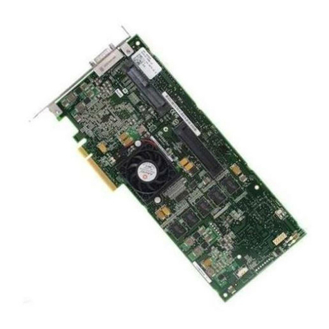
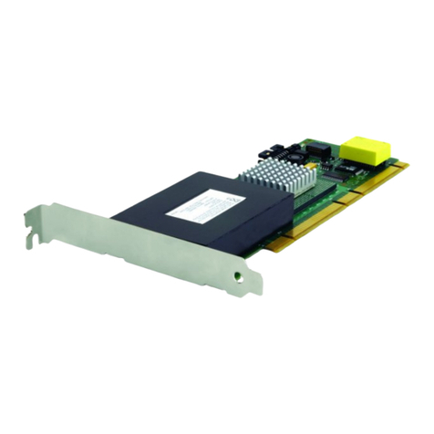
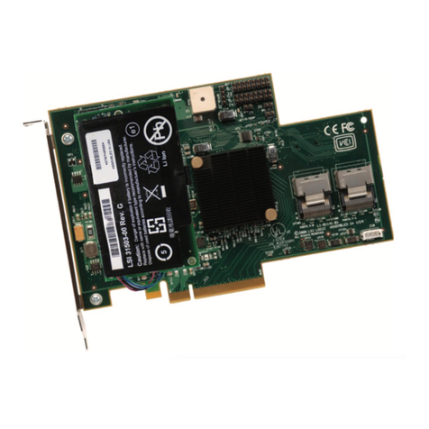
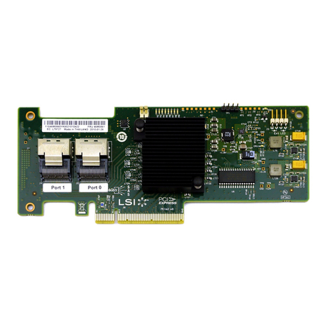
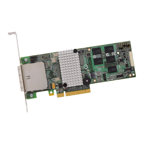
IBM ServeRAID M5210 User manual

®
ServeRAID M5210 SAS/SATA Controller
for IBM System x
User’s Guide
Part Number: 00D2437

Third Edition (July 2014)
© Copyright IBM Corporation 2013.
US Government Users Restricted Rights -- Use, duplication or disclosure restricted by GSA ADP
Schedule Contract with IBM Corp.
July 2014

- 3 -
ServeRAID M5210 SAS/SATA Controller for IBM System x User’s Guide
July 2014
Safety
Safety
Bu ürünü kurmadan önce güvenlik bilgilerini okuyun.
Youq mwngz yungh canjbinj neix gaxgonq, itdingh aeu doeg aen
canjbinj soengq cungj vahgangj ancien siusik.

- 4 -
ServeRAID M5210 SAS/SATA Controller for IBM System x User’s Guide
July 2014
Safety

- 5 -
ServeRAID M5210 SAS/SATA Controller for IBM System x User’s Guide
July 2014
Safety

- 6 -
ServeRAID M5210 SAS/SATA Controller for IBM System x User’s Guide
July 2014
Safety
Statement 28:
CAUTION:
The battery is a lithium ion battery. To avoid possible explosion, do not burn the
battery. Exchange it only with the approved part. Recycle or discard the battery
as instructed by local regulations.

- 1 -
Table of Contents
ServeRAID M5210 SAS/SATA Controller for IBM System x User’s Guide
July 2014
Table of Contents
Chapter 1: Overview . . . . . . . . . . . . . . . . . . . . . . . . . . . . . . . . . . . . . . . . . . . . . . . . . . . . . . . . . . . . . . . . . . . . . . . . . . . . . . . . . . . . . . . . . . . . . . . . . . . . . . . . . . . . 3
1.1 ServeRAID M5210 Controller Description . . . . . . . . . . . . . . . . . . . . . . . . . . . . . . . . . . . . . . . . . . . . . . . . . . . . . . . . . . . . . . . . . . . . . . . . . . . . . . . . . . . . . . . . . . . . .3
1.1.1 Controller Guidelines . . . . . . . . . . . . . . . . . . . . . . . . . . . . . . . . . . . . . . . . . . . . . . . . . . . . . . . . . . . . . . . . . . . . . . . . . . . . . . . . . . . . . . . . . . . . . . . . . . . . . . . . . 3
1.2 Integrated MegaRAID Mode and MegaRAID mode . . . . . . . . . . . . . . . . . . . . . . . . . . . . . . . . . . . . . . . . . . . . . . . . . . . . . . . . . . . . . . . . . . . . . . . . . . . . . . . . . . . .4
1.2.1 Supported RAID Level Upgrades . . . . . . . . . . . . . . . . . . . . . . . . . . . . . . . . . . . . . . . . . . . . . . . . . . . . . . . . . . . . . . . . . . . . . . . . . . . . . . . . . . . . . . . . . . . . . . 4
1.2.2 Summary of RAID Levels . . . . . . . . . . . . . . . . . . . . . . . . . . . . . . . . . . . . . . . . . . . . . . . . . . . . . . . . . . . . . . . . . . . . . . . . . . . . . . . . . . . . . . . . . . . . . . . . . . . . . . 4
1.3 Configuration Scenarios . . . . . . . . . . . . . . . . . . . . . . . . . . . . . . . . . . . . . . . . . . . . . . . . . . . . . . . . . . . . . . . . . . . . . . . . . . . . . . . . . . . . . . . . . . . . . . . . . . . . . . . . . . . . . .5
1.3.1 Number of Physical Disks Supported . . . . . . . . . . . . . . . . . . . . . . . . . . . . . . . . . . . . . . . . . . . . . . . . . . . . . . . . . . . . . . . . . . . . . . . . . . . . . . . . . . . . . . . . . . 6
1.4 Benefits of the SAS Interface. . . . . . . . . . . . . . . . . . . . . . . . . . . . . . . . . . . . . . . . . . . . . . . . . . . . . . . . . . . . . . . . . . . . . . . . . . . . . . . . . . . . . . . . . . . . . . . . . . . . . . . . . .7
1.4.1 PCI Express Architecture . . . . . . . . . . . . . . . . . . . . . . . . . . . . . . . . . . . . . . . . . . . . . . . . . . . . . . . . . . . . . . . . . . . . . . . . . . . . . . . . . . . . . . . . . . . . . . . . . . . . . . 7
1.4.2 Operating System Support. . . . . . . . . . . . . . . . . . . . . . . . . . . . . . . . . . . . . . . . . . . . . . . . . . . . . . . . . . . . . . . . . . . . . . . . . . . . . . . . . . . . . . . . . . . . . . . . . . . . 7
1.5 Benefits of the ServeRAID M5210 SAS/SATA Controller . . . . . . . . . . . . . . . . . . . . . . . . . . . . . . . . . . . . . . . . . . . . . . . . . . . . . . . . . . . . . . . . . . . . . . . . . . . . . . . .7
1.5.1 SAS Features . . . . . . . . . . . . . . . . . . . . . . . . . . . . . . . . . . . . . . . . . . . . . . . . . . . . . . . . . . . . . . . . . . . . . . . . . . . . . . . . . . . . . . . . . . . . . . . . . . . . . . . . . . . . . . . . . 8
1.5.2 SAS Array Limitations . . . . . . . . . . . . . . . . . . . . . . . . . . . . . . . . . . . . . . . . . . . . . . . . . . . . . . . . . . . . . . . . . . . . . . . . . . . . . . . . . . . . . . . . . . . . . . . . . . . . . . . . . 8
1.5.3 SATA III Features. . . . . . . . . . . . . . . . . . . . . . . . . . . . . . . . . . . . . . . . . . . . . . . . . . . . . . . . . . . . . . . . . . . . . . . . . . . . . . . . . . . . . . . . . . . . . . . . . . . . . . . . . . . . . . 9
1.5.4 PCI Express Performance. . . . . . . . . . . . . . . . . . . . . . . . . . . . . . . . . . . . . . . . . . . . . . . . . . . . . . . . . . . . . . . . . . . . . . . . . . . . . . . . . . . . . . . . . . . . . . . . . . . . . . 9
1.5.5 Usability Features. . . . . . . . . . . . . . . . . . . . . . . . . . . . . . . . . . . . . . . . . . . . . . . . . . . . . . . . . . . . . . . . . . . . . . . . . . . . . . . . . . . . . . . . . . . . . . . . . . . . . . . . . . . . 10
1.5.6 Flexibility Features. . . . . . . . . . . . . . . . . . . . . . . . . . . . . . . . . . . . . . . . . . . . . . . . . . . . . . . . . . . . . . . . . . . . . . . . . . . . . . . . . . . . . . . . . . . . . . . . . . . . . . . . . . . 10
1.5.7 CacheCade . . . . . . . . . . . . . . . . . . . . . . . . . . . . . . . . . . . . . . . . . . . . . . . . . . . . . . . . . . . . . . . . . . . . . . . . . . . . . . . . . . . . . . . . . . . . . . . . . . . . . . . . . . . . . . . . . . 10
1.5.8 Protection Information (T10-DIF) . . . . . . . . . . . . . . . . . . . . . . . . . . . . . . . . . . . . . . . . . . . . . . . . . . . . . . . . . . . . . . . . . . . . . . . . . . . . . . . . . . . . . . . . . . . . . 10
1.5.9 Drive Roaming . . . . . . . . . . . . . . . . . . . . . . . . . . . . . . . . . . . . . . . . . . . . . . . . . . . . . . . . . . . . . . . . . . . . . . . . . . . . . . . . . . . . . . . . . . . . . . . . . . . . . . . . . . . . . . 11
1.5.10 Drive Migration . . . . . . . . . . . . . . . . . . . . . . . . . . . . . . . . . . . . . . . . . . . . . . . . . . . . . . . . . . . . . . . . . . . . . . . . . . . . . . . . . . . . . . . . . . . . . . . . . . . . . . . . . . . . 12
1.5.11 New Drives Attached to a ServeRAID Controller . . . . . . . . . . . . . . . . . . . . . . . . . . . . . . . . . . . . . . . . . . . . . . . . . . . . . . . . . . . . . . . . . . . . . . . . . . . . . 12
1.5.12 Automatic Rebuilds on New Drives. . . . . . . . . . . . . . . . . . . . . . . . . . . . . . . . . . . . . . . . . . . . . . . . . . . . . . . . . . . . . . . . . . . . . . . . . . . . . . . . . . . . . . . . . . 13
1.5.13 System (JBOD) Drives. . . . . . . . . . . . . . . . . . . . . . . . . . . . . . . . . . . . . . . . . . . . . . . . . . . . . . . . . . . . . . . . . . . . . . . . . . . . . . . . . . . . . . . . . . . . . . . . . . . . . . . 13
1.6 Hardware Specifications. . . . . . . . . . . . . . . . . . . . . . . . . . . . . . . . . . . . . . . . . . . . . . . . . . . . . . . . . . . . . . . . . . . . . . . . . . . . . . . . . . . . . . . . . . . . . . . . . . . . . . . . . . . . .13
1.7 Technical Support. . . . . . . . . . . . . . . . . . . . . . . . . . . . . . . . . . . . . . . . . . . . . . . . . . . . . . . . . . . . . . . . . . . . . . . . . . . . . . . . . . . . . . . . . . . . . . . . . . . . . . . . . . . . . . . . . . .14
Chapter 2: ServeRAID M5210 SAS/SATA Controller for IBM System x User’s Guide . . . . . . . . . . . . . . . . . . . . . . . . . . . . . . . . . . . . . . . . . . . . . . . . . 15
2.1 Requirements. . . . . . . . . . . . . . . . . . . . . . . . . . . . . . . . . . . . . . . . . . . . . . . . . . . . . . . . . . . . . . . . . . . . . . . . . . . . . . . . . . . . . . . . . . . . . . . . . . . . . . . . . . . . . . . . . . . . . . .15
2.2 Hardware installation . . . . . . . . . . . . . . . . . . . . . . . . . . . . . . . . . . . . . . . . . . . . . . . . . . . . . . . . . . . . . . . . . . . . . . . . . . . . . . . . . . . . . . . . . . . . . . . . . . . . . . . . . . . . . . .15
2.3 Connecting a ServeRAID M5210 SAS/SATA Controller to a Drive Backplane on an Enclosure . . . . . . . . . . . . . . . . . . . . . . . . . . . . . . . . . . . . . . . . . . .17
2.4 After Installing the Controller . . . . . . . . . . . . . . . . . . . . . . . . . . . . . . . . . . . . . . . . . . . . . . . . . . . . . . . . . . . . . . . . . . . . . . . . . . . . . . . . . . . . . . . . . . . . . . . . . . . . . . . .18
Chapter 3: ServeRAID M5210 SAS/SATA Controller Characteristics . . . . . . . . . . . . . . . . . . . . . . . . . . . . . . . . . . . . . . . . . . . . . . . . . . . . . . . . . . . . . . . . 19
3.1 Board Layout and Connector Information . . . . . . . . . . . . . . . . . . . . . . . . . . . . . . . . . . . . . . . . . . . . . . . . . . . . . . . . . . . . . . . . . . . . . . . . . . . . . . . . . . . . . . . . . . . .19
3.2 Characteristics of the ServeRAID M5210 SAS/SATA Controller. . . . . . . . . . . . . . . . . . . . . . . . . . . . . . . . . . . . . . . . . . . . . . . . . . . . . . . . . . . . . . . . . . . . . . . . .21
3.2.1 Controller Specifications . . . . . . . . . . . . . . . . . . . . . . . . . . . . . . . . . . . . . . . . . . . . . . . . . . . . . . . . . . . . . . . . . . . . . . . . . . . . . . . . . . . . . . . . . . . . . . . . . . . . . 21
3.2.2 Array Performance Features. . . . . . . . . . . . . . . . . . . . . . . . . . . . . . . . . . . . . . . . . . . . . . . . . . . . . . . . . . . . . . . . . . . . . . . . . . . . . . . . . . . . . . . . . . . . . . . . . . 22
3.2.3 Fault Tolerance . . . . . . . . . . . . . . . . . . . . . . . . . . . . . . . . . . . . . . . . . . . . . . . . . . . . . . . . . . . . . . . . . . . . . . . . . . . . . . . . . . . . . . . . . . . . . . . . . . . . . . . . . . . . . . 23
3.2.4 Power Supply Requirements for the ServeRAID M5210 SAS/SATA Controller. . . . . . . . . . . . . . . . . . . . . . . . . . . . . . . . . . . . . . . . . . . . . . . . . . . 23
3.2.5 Operating and Non-operating Conditions . . . . . . . . . . . . . . . . . . . . . . . . . . . . . . . . . . . . . . . . . . . . . . . . . . . . . . . . . . . . . . . . . . . . . . . . . . . . . . . . . . . . 23
3.2.6 Safety Characteristics . . . . . . . . . . . . . . . . . . . . . . . . . . . . . . . . . . . . . . . . . . . . . . . . . . . . . . . . . . . . . . . . . . . . . . . . . . . . . . . . . . . . . . . . . . . . . . . . . . . . . . . . 23
Appendix A: Getting Help and Technical Assistance . . . . . . . . . . . . . . . . . . . . . . . . . . . . . . . . . . . . . . . . . . . . . . . . . . . . . . . . . . . . . . . . . . . . . . . . . . . . . . 24
A.1 Before You Call . . . . . . . . . . . . . . . . . . . . . . . . . . . . . . . . . . . . . . . . . . . . . . . . . . . . . . . . . . . . . . . . . . . . . . . . . . . . . . . . . . . . . . . . . . . . . . . . . . . . . . . . . . . . . . . . . . . . .24
A.2 Using the Documentation . . . . . . . . . . . . . . . . . . . . . . . . . . . . . . . . . . . . . . . . . . . . . . . . . . . . . . . . . . . . . . . . . . . . . . . . . . . . . . . . . . . . . . . . . . . . . . . . . . . . . . . . . .24
A.3 Getting Help and Information from the World Wide Web . . . . . . . . . . . . . . . . . . . . . . . . . . . . . . . . . . . . . . . . . . . . . . . . . . . . . . . . . . . . . . . . . . . . . . . . . . . .25
- 2 -
ServeRAID M5210 SAS/SATA Controller for IBM System x User’s Guide
July 2014
Table of Contents
A.4 Software Service and Support . . . . . . . . . . . . . . . . . . . . . . . . . . . . . . . . . . . . . . . . . . . . . . . . . . . . . . . . . . . . . . . . . . . . . . . . . . . . . . . . . . . . . . . . . . . . . . . . . . . . . . .25
A.5 Hardware Service and Support . . . . . . . . . . . . . . . . . . . . . . . . . . . . . . . . . . . . . . . . . . . . . . . . . . . . . . . . . . . . . . . . . . . . . . . . . . . . . . . . . . . . . . . . . . . . . . . . . . . . . .25
A.6 IBM Taiwan Product Service . . . . . . . . . . . . . . . . . . . . . . . . . . . . . . . . . . . . . . . . . . . . . . . . . . . . . . . . . . . . . . . . . . . . . . . . . . . . . . . . . . . . . . . . . . . . . . . . . . . . . . . . .25
Appendix B: Notices . . . . . . . . . . . . . . . . . . . . . . . . . . . . . . . . . . . . . . . . . . . . . . . . . . . . . . . . . . . . . . . . . . . . . . . . . . . . . . . . . . . . . . . . . . . . . . . . . . . . . . . . . . . 26
B.1 Trademarks . . . . . . . . . . . . . . . . . . . . . . . . . . . . . . . . . . . . . . . . . . . . . . . . . . . . . . . . . . . . . . . . . . . . . . . . . . . . . . . . . . . . . . . . . . . . . . . . . . . . . . . . . . . . . . . . . . . . . . . .27
B.2 Important Notes . . . . . . . . . . . . . . . . . . . . . . . . . . . . . . . . . . . . . . . . . . . . . . . . . . . . . . . . . . . . . . . . . . . . . . . . . . . . . . . . . . . . . . . . . . . . . . . . . . . . . . . . . . . . . . . . . . . .27
B.3 Documentation Format . . . . . . . . . . . . . . . . . . . . . . . . . . . . . . . . . . . . . . . . . . . . . . . . . . . . . . . . . . . . . . . . . . . . . . . . . . . . . . . . . . . . . . . . . . . . . . . . . . . . . . . . . . . . .28
B.4 Electronic Emission Notices . . . . . . . . . . . . . . . . . . . . . . . . . . . . . . . . . . . . . . . . . . . . . . . . . . . . . . . . . . . . . . . . . . . . . . . . . . . . . . . . . . . . . . . . . . . . . . . . . . . . . . . . .28

- 3 -
ServeRAID M5210 SAS/SATA Controller for IBM System x User’s Guide
July 2014
Chapter 1: Overview
ServeRAID M5210 Controller Description
Chapter 1: Overview
1.1 ServeRAID M5210 Controller Description
The ServeRAID M5210 SAS/SATA controller is a PCI-Express 3.0, half-size, half-height RAID controller based on the
LSISAS3108 PCI Express-SAS/SATA I/O Processor chip.
The controller controls eight internal SAS/SATA ports through two SFF-8643 4i internal mini-SAS HD connectors. The
controller integrates eight high-performance SAS/SATA PHYs and a PCI Express bus master DMA core. Each of the
eight PHYs is capable of 12.0 Gb/s SAS link rates and 6.0 Gb/s SATA III link rates.
The controller brings 12.0 Gb/s SAS and 6.0 Gb/s SATA performance to host controller, workstation, and server designs.
The controller supports internal storage devices, which allows you to use a system that supports enterprise-class SAS
drives, and desktop-class SATA drives. The controller can connect to drives directly. Simplified cabling between
devices is an additional benefit.
The LSISAS3108 ROC device increases system performance and provides fault-tolerant data storage. The LSISAS3108
supports data striping across multiple disks, which reduces disk access time because multiple disks simultaneously
read or write data. In addition, the LSISAS3108 ROC device backs up data with either data mirroring or a parity block.
Either backup method enables you to recover lost data in the event of a disk failure. You can select the data backup
method that best suits your needs. A hardware RAID assist exclusive-OR (XOR) engine speeds parity generation and
checking and reduces system-access times.
The controller supports the SAS protocol as described in the Serial Attached SCSI Standard, version 3.0, and the SATA
III protocol defined by the Serial ATA Revision 3.0 Specification.
Each port on the controller supports SAS devices and/or SATA devices using the following:
SAS Serial SCSI Protocol (SSP), which enables communication with other SAS devices
SATA, which enables communication with other SATA devices
Serial Management Protocol (SMP), which communicates topology management information directly with an
attached SAS expander device
Serial Tunneling Protocol (STP), which enables communication with a SATA device through an attached expander
1.1.1 Controller Guidelines
before you install the controller, read the following guidelines:
You can connect only one device per SAS PHY unless you use an expander
Cables have to meet the SAS specification
You cannot mix SAS drives and SATA drives in the same virtual drive
You cannot mix SAS Solid State Drives (SSDs) or SATA SSDs and existing mechanical drives (SAS or SATA) in the
same virtual drive
You cannot mix Solid State SAS drives and Solid State SATA drives in the same virtual drive
See Section 3.2.4, “Power Supply Requirements for the ServeRAID M5210 SAS/SATA Controller” for information about
the power requirements, and Section 3.2.5, “Operating and Non-operating Conditions”for information about the
minimum and the maximum temperature ranges.
NOTE You cannot mix SAS drives and SATA drives within the same virtual drive.

- 4 -
ServeRAID M5210 SAS/SATA Controller for IBM System x User’s Guide
July 2014
Chapter 1: Overview
Integrated MegaRAID Mode and MegaRAID mode
1.2 Integrated MegaRAID Mode and MegaRAID mode
The ServeRAID M5210 controller can run in either integrated MegaRAID (iMR) mode natively or in MegaRAID (MR)
mode with the addition of a transportable memory module.
iMR is a highly integrated, low-cost RAID solution made possible by Fusion-MPT architecture. Integrated MegaRAID is
a processor-based, hardware RAID solution designed for system environments requiring redundancy and high
availability where a full-featured RAID implementation is not required or might be cost prohibitive.
The major advantage of iMR is that it provides RAID at the processor level, so it does not burden the CPU, which allows
for more efficient operation. iMR mode is native to the ServeRAID M5210 controller and does not require a
transportable memory module.
The major advantage of MR mode is that the it supports more RAID levels than iMR mode. iMR mode supports RAID
levels 0, 1, 5, 10, and 50 and supports 64k stripe size only. MR mode supports RAID levels 0, 1, 5, 6, 10, 50, and 60 and
supports 64k to 1M stripe size.
See Section 1.2.1, “Supported RAID Level Upgrades” for information about these upgrades.
See Section 1.2.2, “Summary of RAID Levels” for information about the supported RAID levels.
1.2.1 Supported RAID Level Upgrades
To use RAID levels 5, 6, 50, or 60 with this controller, you need to install a Feature on Demand upgrade and/or a
transportable memory module, depending on the RAID level.
This controller supports iMR RAID levels 5 and 50 with the following installed Feature on Demand upgrade:
ServeRAID M5200 Series Zero Cache/RAID 5 Upgrade for IBM System x
This controller supports MegaRAID RAID levels 5 and 50, with any of the following installed transportable memory
modules:
ServeRAID M5200 Series 1GB Cache/RAID 5 Upgrade for IBM System x
ServeRAID M5200 Series 1GB Flash/RAID 5 Upgrade for IBM System x
ServeRAID M5200 Series 2GB Flash/RAID 5 Upgrade for IBM System x
ServeRAID M5200 Series 4GB Flash/RAID 5 Upgrade for IBM System x
This controller supports MegaRAID RAID levels 6 and 60 with the ServeRAID M5200 Series RAID 6 Upgrade for IBM
System x
1.2.2 Summary of RAID Levels
RAID levels describe a system for ensuring the availability and redundancy of data stored on large disk subsystems.
NOTE iMR mode RAID 5 requires purchase of the Feature on Demand upgrade.
NOTE MR mode RAID 5/50 requires a transportable memory module (4 options).
NOTE MegaRAID RAID 6/60 requires a transportable memory module (4 options) and the Feature on Demand
upgrade.

- 5 -
ServeRAID M5210 SAS/SATA Controller for IBM System x User’s Guide
July 2014
Chapter 1: Overview
Configuration Scenarios
RAID 0 uses striping to provide high data throughput, especially for large files in an environment that does not require
fault tolerance.
RAID 1 uses mirroring so that data written to one drive is simultaneously written to another drive. This is good for
small databases or other applications that require small capacity but complete data redundancy.
RAID 5 uses disk striping and parity data across all drives (distributed parity) to provide high data throughput,
especially for small random access.
RAID 6 uses distributed parity, with two independent parity blocks per stripe, and disk striping. A RAID 6 virtual drive
can survive the loss of two drives without losing data. A RAID 6 drive group, which requires a minimum of three drives,
is similar to a RAID 5 drive group. Blocks of data and parity information are written across all drives. The parity
information is used to recover the data if one or two drives fail in the drive group.
RAID 10, a combination of RAID 0 and RAID 1, consists of striped data across mirrored spans. A RAID 10 drive group is
a spanned drive group that creates a striped set from a series of mirrored drives. RAID 10 allows a maximum of eight
spans. You must use an even number of drives in each RAID virtual drive in the span. The RAID 1 virtual drives must
have the same stripe size. RAID 10 provides high data throughput and complete data redundancy but uses a larger
number of spans.
RAID 50, a combination of RAID 0 and RAID 5, uses distributed parity and disk striping. A RAID 50 drive group is a
spanned drive group in which data is striped across multiple RAID 5 drive groups. RAID 50 works best with data that
requires high reliability, high request rates, high data transfers, and medium-to-large capacity.
RAID 60, a combination of RAID 0 and RAID 6, uses distributed parity, with two independent parity blocks per stripe in
each RAID set, and disk striping. A RAID 60 virtual drive can survive the loss of two drives in each of the RAID 6 sets
without losing data. It works best with data that requires high reliability, high request rates, high data transfers, and
medium-to-large capacity.
1.3 Configuration Scenarios
There are two main scenarios in which you can use this ServeRAID controller:
Low-end, internal SATA configuration: In this configuration, use the ServeRAID controller as a high-end SATA
compatible controller that connects to several SATA disks. This type of configuration is mostly for low-end or entry
level servers. Enclosure management is provided through out-of-band I2C bus. Side bands of both types of
internal SAS connectors support the SFF-8485 and SFF-8448 (SGPIO) interface.
Midrange, internal SAS configuration: This configuration is like the internal SATA configuration, but with high-end
disks. This type of configuration is more suitable for low-range to midrange servers.
The following figure shows a direct-connect configuration. TheInter-IC (I2C) interface communicates with peripherals.
The external memory bus provides a 32-bit memory bus, parity checking, and chip select signals for pipelined
synchronous burst static random access memory (PSBRAM), nonvolatile static random access memory (NVSRAM), and
Flash ROM.
NOTE Having virtual drives of different RAID levels, such as RAID 0 and RAID 5, in the same drive group is not
allowed. For example, if an existing RAID 5 virtual drive is created out of partial space in an array, the next
virtual drive in the array has to be RAID 5 only.

- 6 -
ServeRAID M5210 SAS/SATA Controller for IBM System x User’s Guide
July 2014
Chapter 1: Overview
Configuration Scenarios
Figure 1 Example of a SAS Direct Connect Application
The following figure shows an example of a ServeRAID controller configured with an expander that is connected to
SAS disks, SATA disks, or both.
Figure 2 Example of a ServeRAID Controller Configured with an Expander
1.3.1 Number of Physical Disks Supported
Your configuration planning for your ServeRAID controller depends in part on the number of physical disks that you
want to use in a RAID array. The number of drives in an array determines the RAID levels that can be supported by this
controller. Only one RAID level can be assigned to each virtual disk. Table 1 shows the minimum number and the
maximum number of drives required for each RAID level.
Table 1 Physical Devices Required for each RAID Level
Raid Level Minimum # of
Physical Devices
Maximum # of
Physical Devices
0 1 32
1 2 32
5 3 32
6 3 32
10 432
50 632
60 632
Flash ROM/
SAS
PCI Express
RAID Controller
SAS/SATA III Device 32-Bit Memory
Address/Data
Bus
PSBRAM/
I2C
SAS/SATA III Device
SAS/SATA III Device
SAS/SATA III Device
PCI Express Interface
NVSRAM
I2C
Interface
Flash ROM/
NVSRAM/
SRAM
I
2
C/UART
PCI Express Interface
SAS/SATA
Drives
8
SRAM
SRAMSDRAM
Peripheral
Bus
72-bit DDR/DDR2
with ECC
Interface
PCI Express to SAS ROC
SAS RAID Controller

- 7 -
ServeRAID M5210 SAS/SATA Controller for IBM System x User’s Guide
July 2014
Chapter 1: Overview
Benefits of the SAS Interface
1.4 Benefits of the SAS Interface
SAS is a serial, point-to-point, enterprise-level device interface that leverages the proven SCSI protocol set. SAS
combines the advantages of SATA, SCSI, and Fibre Channel, and is the future mainstay of the enterprise and high-end
workstation storage markets. SAS offers a higher bandwidth per pin than parallel SCSI, and it improves signal and data
integrity.
The SAS interface uses the proven SCSI command set to ensure reliable data transfers, while providing the
connectivity and flexibility of point-to-point serial data transfers. The serial transmission of SCSI commands eliminates
clock-skew challenges. The SAS interface provides improved performance, simplified cabling, smaller connectors,
lower pin count, and lower power requirements when compared to parallel SCSI.
The ServeRAID M5210 SAS/SATA controller leverages a common electrical and physical connection interface that is
compatible with Serial ATA technology. The SAS protocols and SATA protocols use a thin, 7-wire connector instead of
the 68-wire SCSI cable or 26-wire ATA cable. The SAS/SATA III connector and cable are easier to manipulate, allow
connections to smaller devices, and do not inhibit airflow. The point-to-point SATA III architecture eliminates inherent
difficulties created by the legacy ATA master-slave architecture, while maintaining compatibility with existing ATA
firmware.
1.4.1 PCI Express Architecture
PCI Express is a local bus system designed to increase data transfers without slowing down the central processing unit
(CPU). You can install your ServeRAID M5210SAS/SATA controller in PCI Express computer systems with a standard
bracket type. With this controller in your system, you can connect SCSI devices and SATA devices over the bus.
PCI Express goes beyond the PCI specification in that it is intended as a unifying I/O architecture for various systems:
desktops, workstations, mobile, server, communications, and embedded devices.
1.4.2 Operating System Support
To check for the latest list of supported operating systems and to download the device drivers for those operating
systems, see http://www.ibm.com/systems/support/.
The ServeRAID M5210 controller uses Fusion-MPT architecture for all major operating systems, thinner device drivers,
and better performance.
1.5 Benefits of the ServeRAID M5210 SAS/SATA Controller
This section provides a summary of the features and the benefits of the ServeRAID M5210 SAS/SATA controller. It
contains information on SAS features, SATA features, PCI performance, integration, usability, and flexibility.
The controller offers the following features:
PCI Express x8 lane width
PCI Express performance up to 8 GT/s (1 GB/s) per lane
Two internal connectors
Support for RAID levels 0, 1, 5, 10, and 50 in iMR mode
Support for RAID levels 0, 1, 5, 6, 10, 50, and 60 in MR mode
To use RAID levels 5/50/6/60 with this controller, you need to install a Feature on Demand upgrade and/or a
transportable memory module. See Section 1.2.1, “Supported RAID Level Upgrades” for information about these
upgrades.

- 8 -
ServeRAID M5210 SAS/SATA Controller for IBM System x User’s Guide
July 2014
Chapter 1: Overview
Benefits of the ServeRAID M5210 SAS/SATA Controller
Advanced array configuration and management utilities
Online RAID level migration
Drive migration
Drive roaming
Media scan
No reboot necessary after expansion
More than 200 Qtags per array
User-specified rebuild rate
32-Kbyte nonvolatile random access memory (NVRAM) for storing RAID system configuration information; the
MegaRAID SAS firmware is stored in flash ROM for easy upgrade.
1.5.1 SAS Features
The following list describes the SAS features of the ServeRAID M5210 controller:
Provides eight fully independent PHYs
Supports 12.0 Gb/s SAS data transfers per PHY
Supports SSP to enable communication with other SAS devices
Supports SMP to communicate topology management information
Provides a serial, point-to-point, enterprise-level storage interface
Simplifies cabling between devices
Supports wide ports consisting of 2, 3, or 4 PHYs within a single quad port
Supports narrow ports consisting of a single PHY
Transfers data using SCSI information units
1.5.2 SAS Array Limitations
This section describes the array limitations of the controller. These include limitations such as the number of physical
disks supported, the maximum number of disks per controller, and the maximum number of virtual disks allowed per
controller.
Table 2 lists the array limitations for the ServeRAID M5210 controller.
Table 2 ServeRAID M5210 SAS/SATA Controller Array
Specification ServeRAID M5210
SAS/SATA Controller
Maximum virtual disks per controller 64
Maximum arrays per controller 128
Maximum virtual disks per array 16
Maximum physical devices per array 32
Maximum physical devices per controller 128
NOTE Can support up
to 64 devices, but only
16 can be used in a
RAID configuration.

- 9 -
ServeRAID M5210 SAS/SATA Controller for IBM System x User’s Guide
July 2014
Chapter 1: Overview
Benefits of the ServeRAID M5210 SAS/SATA Controller
The controller supports 64-bit logical block addressing (LBA), which makes it possible to connect a large number of
drives to the RAID controller, directly and through expanders. However, the actual number of drives that you can
attach depends on the limits listed in Table 1 rather than by the actual RAID volume capacity.
The maximum drive numbers in Table 2 depend on how many physical devices you have connected to the controller.
For example, the maximum number of arrays per controller is equal to the number of physical disks supported by the
controller up to the limit of 128 arrays per controller. In addition, though you can have up to 16 virtual disks per array,
and up to 128 arrays per controller, there is a limit of 64 virtual disks per controller.
1.5.3 SATA III Features
The following list describes the SATA III features of the ServeRAID M5210 controller:
Supports SATA III data transfers of 6.0 Gb/s
Supports STP data transfers of 3.0 Gb/s
Provides a serial, point-to-point storage interface
Simplifies cabling between devices
Eliminates the master-slave construction used in parallel ATA
Allows addressing of multiple SATA III targets through an expander
Allows multiple initiators to address a single target (in a fail-over configuration) through an expander
Displays activity and fault indicators for each PHY
Supports Port Selector (for dual-port drives)
Each port on the controller supports SAS devices, SATA devices, or both using SSP, SMP, STP, and SATA. SSP enables
communication with other SAS devices.
Enables the controller to communicate with other SATA devices.
Supports staggered spin-up
Supports hot plug
1.5.4 PCI Express Performance
The following list describes the PCI Express performance features of the ServeRAID M5210 Controller:
Provides a PCI Express 3.0 interface that:
—Supports a dedicated PCI Express bus
—Supports x8 lane configuration
—Supports transfer rates of up to 8 GT/s (1 GB/s) per lane
—Complies with the PCI Express Specification, Revision 3.0
Provides unequaled performance through the Fusion-MPT architecture
Provides high throughput and low CPU utilization to off load the host processor
Maximum hot spares per controller 128
Maximum spans per virtual disk 8
Maximum Ports 2
NOTE The maximum number of hot spares per array is equal to the maximum number of device drivers per
array.
Table 2 ServeRAID M5210 SAS/SATA Controller Array
Specification ServeRAID M5210
SAS/SATA Controller

- 10 -
ServeRAID M5210 SAS/SATA Controller for IBM System x User’s Guide
July 2014
Chapter 1: Overview
Benefits of the ServeRAID M5210 SAS/SATA Controller
1.5.5 Usability Features
The following list describes the usability features of the ServeRAID M5210 controller:
Simplifies cabling with point-to-point, serial architecture
Supports smaller, thinner cables that do not restrict airflow
Provides drive spin-up sequencing control
Provides up to two LED signals for each PHY to indicate link activity and faults
Provides an I2C interface for enclosure management
Supports the external SAS Sideband signal SFF-8485 and SFF-8448 (SGPIO) standards.
1.5.6 Flexibility Features
These features increase the flexibility of the ServeRAID M5210 controller:
Supports a Flash ROM interface, a nonvolatile static RAM (NVSRAM) interface, and a pipelined synchronous burst
SRAM (PSBRAM) interface
Offers a flexible programming interface to tune I/O performance
Allows mixed connections to SAS targets or SATA III targets
Leverages compatible connectors for SAS connections and SATA III connections
Allows grouping of up to four PHYs in a single quad port to form a wide port
Allows programming of the World Wide Name
1.5.7 CacheCade
CacheCade is an advanced software option that is designed to accelerate the performance of hard disk drive (HDD)
arrays with only an incremental investment in SSD technology. The MegaRAID CacheCade software utilizes SSDs as a
dedicated pool of high-performance cache in front of HDDs to maximize I/O performance for transaction intensive
applications. The key benefits of this software option include:
Accelerated performance of existing HDD arrays with a small up-front investment
Read and Write caching of hot spot data for significant reduction in I/O latency
Optimized for real-world workloads of transaction-intensive applicaitons
Simple, intuitive management tools to assign and manage CacheCade SSD pool
These features help reduce latency bottlenecks for server-based HDD volumes. Applications are often constrained by
the performance limitations of their existing HDDs. With this type of storage infrastructure already in place, a switch to
a new array based purely on SSDs is cost prohibitive. Although SSDs are capable of many more transactions per
second than HDDs, SSDs have a very high cost per gigabyte and are not suited for heavy, large file workloads. You can
accelerate the performance of existing HDD arrays without making substantial investments in new hardware by
deploying LSI MegaRAID CacheCade software, which leverages SSDs in front of HDD volumes to create high-capacity,
high-performance controller cache pools.
1.5.8 Protection Information (T10-DIF)
The T10 Technical Committee of the INCITS standardized the basic requirements to implement a data protection
model for end-to-end data protection. This model protects your data within a storage system from various sources of
corruption that historically have gone undetected. Examples of corruption sources include hardware data path errors
(such as FIFO overruns and underruns), firmware errors (such as arithmetic overflow or incorrect pointer usage), and
external agents overwriting the data in memory.

- 11 -
ServeRAID M5210 SAS/SATA Controller for IBM System x User’s Guide
July 2014
Chapter 1: Overview
Benefits of the ServeRAID M5210 SAS/SATA Controller
A fundamental component of the T10 data protection model is the addition of 8 bytes of extra protection information
transferred with each block of user data in the storage system, as shown in the following figure. Although not
specifically named in the T10 standards, this collection of 8 bytes is commonly referred to as the DIF. The DIF contains
three distinct values: a 2-byte logical block guard, a 2-byte logical block application tag, and a 4-byte logical block
reference tag. The T10 specification defines four types of usage models of data protection: Type 0, Type 1, Type 2, and
Type 3 (refer to the most current revision of INCITS T10/1799-D for further information)
Figure 3 T10 Data Integrity Field for MegaRAID Protection Information
1.5.9 Drive Roaming
Drive roaming occurs when the physical disks are changed to different ports on the same controller. When the drives
are placed on different channels, the controller detects the RAID configuration from the configuration data on the
drives.
Configuration data is saved in both the NVRAM on the RAID controller and on the drives attached to the controller.
This action maintains the integrity of the data on each drive, even if the drives have changed their target ID.
Follow these steps to use drive roaming:
1. Turn off the power to the server and all physical disks, enclosures, and system components. Disconnect the power
cords from the system.
2. Remove the server cover by following the instructions in the host system technical documentation.
3. Move the drives to different positions on the backplane to change the targets.
4. Determine the SAS target requirements.
5. Perform a safety check.
6. Make sure that the drives are inserted correctly.
7. Reinstall the server cover.
8. Reconnect the power cords to the system.
9. Turn on the power to the system.
10. The controller then detects the RAID configuration from the configuration data on the drives.
NOTE In a clustering environment, drive roaming is supported within the same channel only.
NOTE If you move a drive that is being rebuilt, the rebuild operation restarts; it does not resume from where
the rebuild operation stopped.

- 12 -
ServeRAID M5210 SAS/SATA Controller for IBM System x User’s Guide
July 2014
Chapter 1: Overview
Benefits of the ServeRAID M5210 SAS/SATA Controller
1.5.10 Drive Migration
Drive migration is the transfer of a set of drives in an existing configuration from one controller to another. The
drives must remain on the same channel and must be reinstalled in the same order as in the original
configuration. The controller to which you migrate the drives cannot have an existing configuration.
Follow these steps to migrate drives:
1. Make sure that you clear the configuration on the system to which you migrate the drives, to prevent a
configuration data mismatch between the drives and the NVRAM.
2. Turn off the power to the server and all physical disks, enclosures, and system components. Disconnect the power
cords from the systems.
3. Open the host system, following the instructions in the host system technical documentation.
4. Remove the SAS cable connectors from the internal drives that you want to migrate.
5. Make sure that pin 1 on the cable matches pin 1 on the connector.
6. Make sure that the SAS cables conform to all SAS specifications.
7. Remove the physical disks from the first system, and insert them into drive bays on the second system.
8. Connect the SAS cables to the physical disks in the second system.
9. Determine the SAS target requirements.
10. Perform a safety check.
11. Make sure that all of the cables are attached correctly.
12. Make sure that the RAID controller is installed correctly.
13. Reinstall the server cover.
14. Reconnect the power cords to the system.
15. Turn on the power to the system.
16. The controller detects the RAID configuration from the configuration data on the drives.
1.5.11 New Drives Attached to a ServeRAID Controller
In the Integrated RAID mode, when you insert a new drive with valid metadata into a ServeRAID system, the drive
state of the new drive is either foreign or unconfigured bad.
The specific drive state depends on the Maintain PD Fail History setting, and whether the drive had been inserted in
the system before. The Maintain PD Fail History setting, when enabled, maintains the history of all drive failures.
NOTE Only whole virtual disks can be migrated automatically; partial virtual disks can be migrated manually.
NOTE Drive roaming and drive migration cannot be supported at the same time.
NOTE When you migrate drives, move only the disks that make up the virtual disk (not all of the physical disks
in an array), so that you do not have an NVRAM mismatch error (providing a configuration is on the
destination controller). The NVRAM mismatch error appears only if you move all of the drives to the other
controller.

- 13 -
ServeRAID M5210 SAS/SATA Controller for IBM System x User’s Guide
July 2014
Chapter 1: Overview
Hardware Specifications
A foreign configuration is a storage configuration that already exists on the new drive that you install in the system.
The configuration utilities allow you to import the foreign configuration to the controller, or to clear the configuration
so you can create a new configuration using the new drive.
1.5.12 Automatic Rebuilds on New Drives
Automatic rebuilds occur when the drive slot status changes. For example, an automatic rebuild occurs when you
insert a new drive or when you remove a drive and a hot spare replaces the removed drive.
1.5.13 System (JBOD) Drives
The iMR mode supports drives in pass-through mode, which are identified as "system" drives. These drives are also
known as JBOD (Just a Bunch of Disks) drives. When a drive without valid metadata is inserted in a system, if the drive
has a drive state of unconfigured good, it is identified as unconfigured good; otherwise, the drive is marked as a
system drive.
System drives are exposed directly to the operating system. The host system can read data from and write data to the
system drives; however, you cannot use system drives in a RAID configuration.
You can change system drives into unconfigured good drives (you can also change unconfigured good drives into
system drives). When a system drive is changed to an unconfigured good drive, the unconfigured good drive state of
the drive is maintained after reboot, drive removal, or drive insertion.
You can use system drives as bootable drives. iMR supports up to 63 system drives and up to 16 unconfigured good
drives.
1.6 Hardware Specifications
You can install your ServeRAID M5210 controller in a computer with a mainboard that has a PCI Express slot. Table 1.3
describes the hardware configuration features of the controller.
NOTE See the ServeRAID-M Software User’s Guide for the procedures used to import a foreign configuration
or change a drive state from unconfigured bad to unconfigured good.
Table 3 ServeRAID M5210 SAS/SATA Controller
RAID Levels iMR Mode: 0, 1, 5, 10, and 50
MR Mode: 0, 1, 5, 6, 10, 50, and, 60
NOTE To use certain RAID levels with this controller, you
need to install a Feature on Demand upgrade and/or a
transportable memory module. See Section1.3.1 for more
information
Devices Supported per Port Up to 8 SAS devices or 8 SATA devices (such as drives and
expanders)
Ports Eight Internal
Data Transfer Rate Up to 12Gb/s per phy
Bus PCI Express 3.0
Cache Function No. See the note at the bottom of this table

- 14 -
ServeRAID M5210 SAS/SATA Controller for IBM System x User’s Guide
July 2014
Chapter 1: Overview
Technical Support
1.7 Technical Support
For information about the technical support available for this product, see Appendix A:
Multiple Virtual Disks per Controller Yes. Up to 64 virtual disks per controller
Multiple Arrays per Controller Yes. Up to 64 virtual disks per controller
Online Capacity Expansion Yes
Dedicated and Global Hot Spares Yes
Hot Swap Devices Supported Yes
Non-Disk Devices Supported Yes
Mixed Capacity Physical Disks Supported Yes
Number of Internal Connectors Two SFF-8643 4i internal mini-SAS HD connectors
Hardware Exclusive OR (XOR) Assistance Yes
Direct I/O Yes
Architecture Fusion-MPT
NOTE In MR mode, the ServeRAID M5210 SAS\SATA controller supports cache policy, which includes
write-back, write-through, adaptive read ahead, non-read ahead, read ahead, cache I/O, and direct I/O
settings. However, in iMR mode, the controller does not support these cache policy settings. See
Section 1.2, “Integrated MegaRAID Mode and MegaRAID mode” for more information about MR mode
and iMR mode.
Table 3 ServeRAID M5210 SAS/SATA Controller
Table of contents
Other IBM Controllers manuals

IBM
IBM MiEM78P468L Owner's manual

IBM
IBM ServeRAID-8 Series Instructions for use

IBM
IBM 3746-900 User manual

IBM
IBM 3746 User manual

IBM
IBM SAS RAID Series User manual

IBM
IBM 3746-900 Instruction Manual

IBM
IBM 3708 Service manual

IBM
IBM SAN Volume Controller 2145-CG8 Manual

IBM
IBM 3174 Reference manual

IBM
IBM FlashSystem 5000 User manual

IBM
IBM 3745 Series User manual

IBM
IBM 8248-L4T User manual

IBM
IBM 3270 User manual

IBM
IBM BladeCenter T Series User manual

IBM
IBM 3708 Technical manual

IBM
IBM 3745 Series Parts list manual

IBM
IBM CPC700 User manual

IBM
IBM ServeRAID M5016 User manual

IBM
IBM Nways 3746-900 Service manual

IBM
IBM Redbooks ServeRAID-MR10i User manual