AutoLoc AUTSL35 Instruction Manual

1
WWW.AUTOLOC.COMTECH SUPPORT: 503.693.1918
SHAVE DOOR HANDLE SYSTEMS
Mount your solenoid in a DRY location.
We recommend using the Autoloc Solenoid Relocation Kit
(AUTSVAEX) to mount the solenoid inside the vehicle.
Mount the relay in a dry location.
Only use a high-AMP approved relay.
(AUTRA1000)
Make sure the mounting bracket has a
good chassis ground.
For optimal performance make sure to leave slack in the
cable. Do not make the cable too tight!
Make sure to always protect your connections to the
battery, using the appropriate fuses or circuit breakers.
AUTSVPRO
Mount in Dry
Location
Install Circuit
Protection
Good Ground
Required
Use High
Amp Relay
Leave Slack
in Cable
Autoloc Shaved Door Kits set the standard for shaved doors done right,
and your kit will provide you with years of flawless operation, however
the kit must be installed properly. Follow the guidelines below and all
instructions on the following pages closely.
PART # PROTECTION
AUTSL35 30 Amp Fuse
AUTSL50 40/50 Amp CB
AUTSL75/100 60/70 Amp CB
CB = Circuit Breaker
©2019 The Hoffman Group L. L. C. All rights reserved. AUTSVPRO Rev5 1 of 4 01/22/2019
The above instructions are for reference only. THG LLC is not responsible for any inaccuracies in the above instructions. THG LLC is also not responsible for any property damage or personal injuries resulting from the
above instructions. Installation by qualified automotive professionals is highly recommended.
2
WWW.AUTOLOC.COMTECH SUPPORT: 503.693.1918
SHAVE DOOR HANDLE SYSTEMS
AUTSVPRO
©2019 The Hoffman Group L. L. C. All rights reserved. AUTSVPRO Rev5 2 of 4 01/22/2019
The above instructions are for reference only. THG LLC is not responsible for any inaccuracies in the above instructions. THG LLC is also not responsible for any property damage or personal injuries resulting from the
above instructions. Installation by qualified automotive professionals is highly recommended.
GREEN/WHITE
ETIHW/EULB
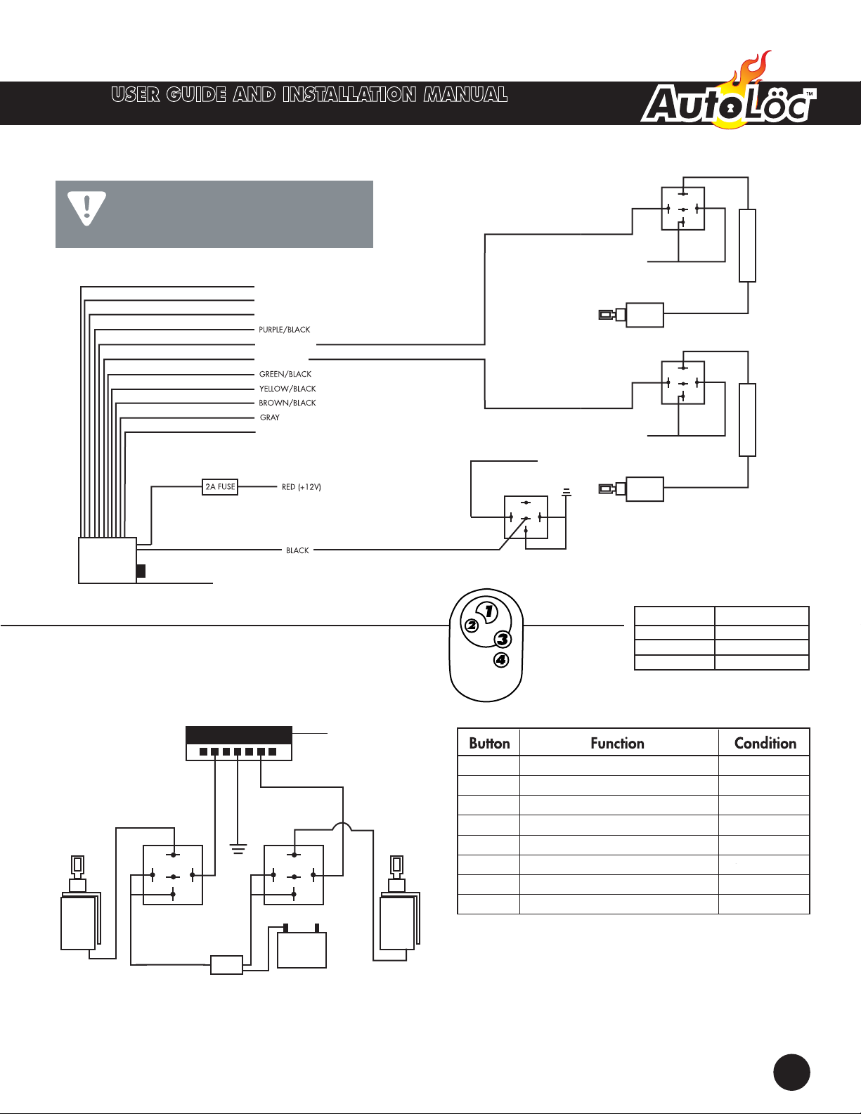
MULTI-FUNCTION KITS
DOOR RELAY DOOR RELAY
+ –
REVIRD
REGNESSAP
87
87a
30
86
85 87
87a
30
86
85
FUSE
30A
Remote Receiver
Connector
Please reference the
receivers wiring diagram for
all other wire connections.
IMPORTANT!
IMPORTANT NOTICE: Upon completion of installation,
you may have extra unused wires on the wiring
harness. Do not be concerned. These wires are used
for features available on other models.
+12V
87
87a
30
86
85
RELAY
Solenoid
DRIVER
DOOR SOLENOID
+12V
87
87a
30
86
85
RELAY
Solenoid
PASSENGER
DOOR SOLENOID
(CH1 – 500 mA)
(CH2 – 500 mA)
(CH3 – 500 mA)
(CH4 – 500 mA)
(STARTER/IGNITION KILL OUTPUT)
RED/BLACK (CH5 – 500mA)
VALET SWITCH
WHITE/BLACK (CH6 – 500mA)
ORANGE (FOR PROGRAMMING ONLY)
YELLOW (12V CONSTANT POWER - FOR PROGRAMMING ONLY)
Keyless
Unit
CHASSIS
GROUND
SAFETY
RELAY 87
87a
30
86
85
SWITCH IGNITION POWER
1 Drivers Door Anytime
2 Passengers Door Anytime
3 1st channel output Anytime
4 2nd channel output Anytime
1 + 3 3rd channel output Anytime
2 + 4 4th channel output Anytime
1 + 2 5th channel output Anytime
3 + 4 6th channel output Anytime
BLACK
CODE LEARNING
a. Connect 12 volt constant power to yellow wire on receiver. Press and hold valet button
for 3 - 5 seconds. The orange wire will receive a momentary ground signal to indicate
code learning mode. A test light can be used to see the ground signal. The test light will
flash once to indicate code learning mode achieved. Press any button on the remote to
be programed within 30 seconds. Test light will flash again to indicate remote has been
accepted. Up to 4 remotes may be learned. Disconnect power to yellow wire. System
will automatically exit programing mode.
ALWAYS USE PROTECTION
Make sure to always protect your
connections to the battery, using the
appropirate fuses or circuit breakers.
PART # PROTECTION
AUTSL35 30 Amp Fuse
AUTSL50 40/50 Amp CB
AUTSL75/100 60/70 Amp CB
CB = Circuit Breaker
*ALL OUPUTS ARE NEGATIVE
Ground signals.
Connect to groundside of circuit.
ANTENNA
CIRCUIT BREAKER
40 AMP (NOT INCLUDED)
CIRCUIT BREAKER
40 AMP (NOT INCLUDED)
GREEN/WHITE
BLUE/WHITE

3
ALARM KITS
DOOR RELAY DOOR RELAY
+ –
REVIRD
EGNESSAP R
87
87a
30
86
85 87
87a
30
86
85
FUSE
30A
Remote Receiver
Connector
Please reference the
receivers wiring diagram for
all other wire connections.
IMPORTANT!
EULB/NWORB
PURPLE
ETIHW/NEERG
CABLE
SOLENOID
OEM
LATCH
CABLE
HOUSING
DIONELOS
CABLE
CRIMP
CABLE
CRIMP
IMPORTANT NOTICE: Upon completion of installation,
you may have extra unused wires on the wiring
harness. Do not be concerned. These wires are used
for features available on other models.
SOLENOID INSTALLATION
WWW.AUTOLOC.COMTECH SUPPORT: 503.693.1918
SHAVE DOOR HANDLE SYSTEMS
1. Using the 2 standard screws and washers provided,
attach the bracket to the solenoid. Install the smaller screw
and washer on the solenoid’s rear terminal.
2. Remove the door’s interior panel to locate the factory
latch. Clean and lubricate the latch.
3. Using the hex bolts, mount the solenoid to a clean piece
of metal in a dry location. Ideally you want to mount the
solenoid so you have adirect pull from the door latch to the
solenoid. If you are unable to mount the solenoid with a
direct pull, relocate the solenoid. In some cases you will need
to use the cable extension kit (SVAEX) to redirect the cable
from the latch to the solenoid. (See figure 1)
4. Create a loop with the cable and secure with the alumi-
num crimp around the door latch. (see figure 2) Run the
cable through the door while avoiding all moving parts to
the solenoid.
5. Run the cable through the eye of the solenoid, create a
loop, and secure with the aluminum crimp. (see figure 3)
NOTE: For best performance you’ll want to leave a little
slack in the cable.
AUTSVPRO
©2019 The Hoffman Group L. L. C. All rights reserved. AUTSVPRO Rev5 3 of 4 01/22/2019
The above instructions are for reference only. THG LLC is not responsible for any inaccuracies in the above instructions. THG LLC is also not responsible for any property damage or personal injuries resulting from the
above instructions. Installation by qualified automotive professionals is highly recommended.
FIGURE 3FIGURE 2FIGURE 1

AUTSVPRO
4
WWW.AUTOLOC.COMTECH SUPPORT: 503.693.1918
SHAVE DOOR HANDLE SYSTEMS
OVERALL DIAGRAM
15/20 AMP
CIRCUIT BREAKER
+ –
Solenoid Solenoid
BATTERY
DRIVERS
SIDE
PASSENGERS
SIDE
SOLENOID
CONTROL
RELAY
BRACKET
GROUND
BRACKET
GROUND
SOLENOID CONTROL RELAY
87
87a
30 86
85
+12V CONSTANT
(10/8 GAUGE)
+12V CONSTANT
**OPTIONAL
**Input from optional S-7
OUTPUT TO SOLENOID
(10/8 GAUGE)
NEGATIVE “TRIGGER”
FROM KEYLESS
AND/OR
INTERIOR BUTTON
ACCESSORY RECOMMENDATIONS
KICCB40 - 40 Amp Circuit Breaker
AUTDP3000 - Door Popper
AUTADJCBL - Adjustable Cable Clamp
KICDLOOMBL - 12 Inch Door Loom
AUTSVERKEY - Manual Emergency Release
SOLENOID
CONTROL
RELAY
S-7
Pole 86
OPTIONAL SAFETY RELAY
IGNITION/SWITCHED POWER
KEYLESS RECEIVER GROUND SUPPLY
GROUND
SAFETY RELAY
87
87a
30
86
85
CHASSIS GROUND
©2019 The Hoffman Group L. L. C. All rights reserved. AUTSVPRO Rev5 4 of 4 01/22/2019
The above instructions are for reference only. THG LLC is not responsible for any inaccuracies in the above instructions. THG LLC is also not responsible for any property damage or personal injuries resulting from the
above instructions. Installation by qualified automotive professionals is highly recommended.
Pole 85 – goes to 12 volts constant fused at 1 amp minimum / 5 amps maximum
Pole 86 – goes to negative trigger activation wire from remote unit
Pole 87 – output to solenoid
Pole 87a – not used
Pole 30 – goes to 12 volts constant ( *see below )
* Directly from the battery, use 10 gauge minimum / 8 gauge maximum wire, use a 15 to 20 amp circuit breaker within 18 inches of the battery
OPTIONAL SAFETY RELAY
Safety relay wiring ( THIS DIAGRAM WILL PROHIBIT THE SOLENOIDS FROM OPERATING ANYTIME THE KEY IS IN THE ON POSITION )
Pole 85 – connects to ground
Pole 86 – connects to the ignition or accessory wire
Pole 87 – not used
Pole 87a – connects to chassis ground
Pole 30 – connects to ground supply of keyless entry receiver
OPTIONAL - an emergency release cable is recommended for additional fail safe security ( recommended to be installed on the passenger door )
( AutoLoc part number: AUTSVERKD )
&
TIPS TRICKS for your solenoid wiring

Instructions
New & Old
Search our system for the
latest version of instructions
& old ones too!
One Spot
Look No Further
All of the product
information you need is
in one spot.
Updates
Be In The Know
Get notifications for product
changes, recalls, technical
data & more!
This manual suits for next models
3
Table of contents
Other AutoLoc Automobile Accessories manuals


