Automatic Technology Australia Axess Pro Series User manual

AUTOMATIC TECHNOLOGY AUSTRALIA PTY LTD
OWNERS COPY
Installation Instructions
COMMERCIAL ROLLER
SHUTTER OPENER
Pro Series 2160v2
NOTE: A Photo Electric Beam
Sensor must be fitted with this
opener. Failure to comply will
void the warranty and may cause
serious personal injury and/or
property damage.
WARNING
It is vital for the safety of persons to follow all
instructions. Failure to comply with the installation
instructions and the safety warnings may result in
serious personal injury and/or property and remote
control opener damage.
Please save these instructions for future reference.


CONTENTS
PAGE CONTENTS
4 IMPORTANT SAFETY WARNINGS
5 FEATURES
6 PRODUCT DESCRIPTION
6 DRIVE UNIT INSTALLATION
8 CONTROL BOARD LAYOUT
9 WIRING DIAGRAM - THREE PHASE LEFT HAND INSTALLATION
10 WIRING DIAGRAM - THREE PHASE RIGHT HAND INSTALLATION
11 MENU STRUCTURE
12 INITIAL ELECTRICAL INSTALLATION
12 POWERING UP THE DRIVE UNIT
13 SETTING TRAVEL LIMITS
15 SETTING PEDESTRIAN POSITION
16 DESCRIPTION OF STANDARD OPERATION
17 CONTROL BOARD ADJUSTMENTS
17 MENU 3 AUTO-CLOSE TIMES
18 MENU 4 LOCK TIMES
18 MENU 5 LIGHT TIMES
18 MENU 6 MOTOR SETTINGS
19 MENU 7 OPERATING MODES
20 PARAMETER VIEWING AND EDITING
21 CODING TRANSMITTERS
22 TRANSMITTER EDIT PROCEDURE
23 TRANSMITTER LIST MANAGEMENT
24 CODE OPERATION (LOCATION EMPTY)
24 CODE OPERATION (LOCATION USED)
24 DELETE OPERATION
26 EDIT OPERATION
24 COPY OPERATION
25 REMOTE CODE SET PROCEDURE
26 DIAGNOSTIC TOOLS (MENU 8)
26 MENU 8.1 TEST INPUTS
26 MENU 8.2 TEST TX’ERS
26 MENU 8.3 DISPLAY HISTORY
26 MENU 8.4 MEMORY USAGE
27 MENU 8.5 SERVICE COUNTER
27 MENU 8.6 COUNTERS
27 MENU 8.7 INSTALLATION
27 MEMORY TOOLS (MENU 9)
27 MENU 9.1 CLR CONTROL
27 MENU 9.2 CLR TX’ERS
27 MENU 9.3 BACKUP MEMORY
27 MENU 9.4 RESTORE TX’ERS
27 MENU 9.5 IMPORT LABELS
28 ACCESSORIES INSTALLATION
29 TROUBLE SHOOTING GUIDE
29 SYSTEM SPECIFICATIONS
30 MAINTENANCE RECORD
31 PARTS LIST
33 WARRANTY AND EXCLUSION OF LIABILITY
Automatic Technology Australia Pty Ltd to the extent that such may be lawfully excluded hereby expressly disclaims all
conditions or warranties, statutory or otherwise which may be implied by laws as conditions or warranties of purchase of
an Automatic Technology Australia Pty Ltd automatic opener and Automatic Technology Australia Pty Ltd hereby
further expressly excludes all or any liability for any injury, damage, cost, expense or claim whatsoever suffered by any
person as a result whether directly or indirectly from failure to install the Automatic Technology Australia automatic
opener in accordance with these installation instructions.
PLEASE READ THESE IMPORTANT SAFETY RULES
4
PLEASE READ THIS INSTRUCTION MANUAL BEFORE ATTEMPTING TO INSTALL
OR USE THE OPENER. FAILURE TO COMPLY WITH THE INSTALLATION
INSTRUCTIONS MAY RESULT IN SERIOUS INJURY AND/OR PROPERTY DAMAGE.
For SAFETY protection a Photo Electric Beam MUST
be fitted with this opener. Failure to comply will void
the warranty and may result in serious personal injury
and/or property damage
DO NOT operate the opener unless the door is in full
view and free from objects such as cars and
children/persons. Make sure that the door has finished
moving before entering or leaving the driveway.
DO NOT operate the opener when
children/persons are near the door. Children must be
supervised near the door at all times when the
opener is in use. SERIOUS PERSONAL INJURY
and/or property damage can result from failure to follow
this warning.
DO NOT allow children to operate the opener.
SERIOUS PERSONAL INJURY AND/OR
PROPERTY DAMAGE can result from failure to
follow this warning.
Make sure that the SAFETY OBSTRUCTION
DETECTION system is working correctly, and is
TESTED every month. Test as per the Installation
Instructions Manual. Adjust if necessary and recheck.
Failure to follow this rule could result in SERIOUS
PERSONAL INJURY and/or property damage. This
test must be repeated at regular intervals and the
necessary adjustments made as required.
If using a key switch or keypad or any device that can
operate the opener, make sure it is out of reach of
children and that the doorway is in full view at all times.
Make sure that remote controls are kept out of reach of
children.
Warning - It is vital for the safety of persons to follow all instructions. Failure to comply
with the following Safety Rules may result in serious personal injury and/or property damage.
The opener is not showerproof - it should not be
immersed in water or sprayed directly by a hose or other
water carrying device.
The door must be WELL BALANCED. and in good
working order. A faulty door must be repaired by a
qualified technician prior to opener installation.
REMOVE OR DISENGAGE all locks and
mechanisms prior to installation of the opener.
Keep hands and loose clothing CLEAR of the door and
opener at all times.
When using auto close mode a PHOTO ELECTRIC
BEAM must be fitted correctly and tested for operation
at regular intervals. EXTREME CAUTION is
recommended when using auto close mode. ALL
SAFETY RULES above must be followed.
In order for the opener to SENSE an object obstructing
the doorway, some FORCE must be exerted on the
object. As a result the object, door and/or person may
suffer DAMAGE or INJURY.
Make sure that the door is fully open before driving into
or out of the driveway. And make sure the door is fully
closed before leaving the driveway.
The opener is not intended for use by young children or
infirm persons without adequate supervision. Children
should be supervised to ensure that they do not play with
the remote transmitters or the opener.
Frequently examine the installation, in particular guides
and mountings for signs of wear, damage or imbalance.
DO NOT use if repair or adjustment is needed since a
fault in the installation or an incorrectly balanced door
may cause injury.

5
FEATURES
Thank you for purchasing the ATA Axess
Automatic Opener. This opener is
designed to suit commercial heavy duty
roller shutter doors. The components and
materials used in this opener are of the
latest technology and highest quality.
Listed below are some of the many
features.
OPERATION
To operate the door opener simply activate
one the integrated controller’s control
inputs using a remote control transmitter,
keypad or many other devices such as key
switch, swipe card, loop detector, etc. In
response the door will then open, stop or
close as requested. Optionally, the
opener can be configured to automatically
close after operation using one of several
auto-close modes.
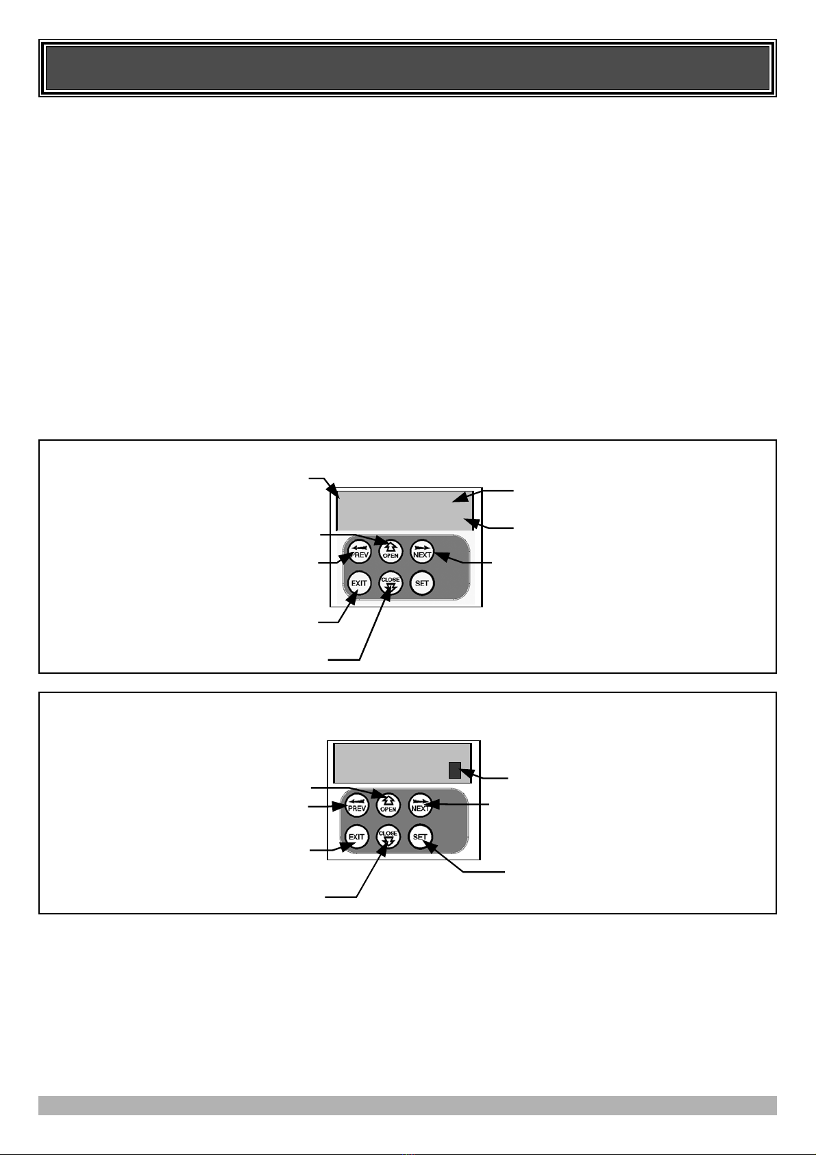
OPERATOR CONSOLE
Incorporated into the integrated controller
is a simple to use operator console which
consists of several buttons and a display.
The console offers a user freindly menu
system that greatly simplifies installation,
adjustments and status indication. Features
include editing transmitter storage and
names, setting various parameters,
selecting specialised operating modes and
performing system diagnostics.
STATUS INDICATION
The status of the door opener can be
determined at anytime by observing the
console’s screen. When the MAIN
SCREEN is displayed, the current
position of the door or the result of the last
movement can be found. The display will
also show the count down progress of the
auto-close timers. Any active input will
also be displayed along with the state of
various features such as periodic service
and vacation mode.
HOPPING CODE TRANSMITTERS
The opener incorporates a hopping code
remote control receiver. Hopping code
transmitters generate a new encrypted
access code (chosen at random) each time
they are activated. As the receiver is able
to track the encryption sequence and reject
access codes that have already been
received, it is able to reject unauthorised
access requested attempted by thieves. In
addition to this, each transmitter has a
unique serial number - so no two are alike.
Further, with a huge error rejection rate
which allows less than 1 error in 1019 the
security of the remote control system is
greatly enhanced.
SECURITY CODE STORE
The opener uses state of the art technology
in storing your selected transmitter codes.
Up to 511 different transmitters can be
stored in the opener’s memory with the
facility to assign a 11 character name to
each transmitter.
REMOTE LIMITS POSITIONING
During installation, a hand held transmitter
can be used when setting the door travel
limits. This allows the installer to closely
observe and control the doors movement
from any position rather than having to be
within arms reach of the console.
CONTROLLING LOCK AND
LIGHTS
The controller has dedicated outputs for
operating a electric lock and warning or
courtesy lights. The timing of these
outputs can be adjusted to suit your needs.
EXTENSIVE OPERATING MODES
VIA CONTROL INPUTS AND
REMOTE CONTROL
The integrated controller can be
configured to operate in many different
ways via its 7 control and safety inputs
which include P.E, OPEN, STOP, CLOSE,
OSC, SWIPE and PEDESTRIAN. Remote
control operation is provided with each
transmitter’s button being able to be con-
figured to operate one of OSC,
PEDESTRIAN, SWIPE, CLOSE, OPEN,
STOP, LIGHT or VACATION functions.
The controllers functionality is further
enhanced by 4 auto-close modes, 3 P.E
response modes and two pedestrian
response modes. For details refer to
relevant instruction manual sections.
MANUAL OPERATION
The opener is equipped with a unique
manual operation device. If the power to
the opener is disrupted for any reason the
clutch disengages and the door can move
manually via the manual chain. When
power is restored the clutch re-engages to
allow automatic operation.

PRODUCT DESCRIPTION
6
DRIVE UNIT INSTALLATION
The ATA Axess Roller Shutter Opener consists of
one drive unit, Logic control box, and two PTX-4
keyring transmitters.
LOGIC CONTROLLER
Housed in a commercial heavy duty enclosure is a set of magnetic
contactors and intelligent logic controller. A 415V three phase
power is required direct connection. The enclosure meets the IP55
standard for ingress of dust and water.
MECHANICAL DRIVE UNIT
The drive unit consists of a powerful 415V three phase motor,
rugged gearbox. It inlcudes a cluth mechanism to allow easy man-
ual operation and is rated to IP42 standard.
The ATA Axess Roller Shutter Opener is designed to operate
most commercial and heavy duty slat roller shutter doors. The
doors must be in good working condition and travel freely in the
guides.
INITIAL CHECK
Before commencing installation check the following:
1. The door moves freely for the full travel in both directions.
2. The mounting must be solid construction (concrete, brick or
steel. It must be able to withstand the full force applied to the
door.
3. A 415V three phase power is required direct connection.
4. Photoelectric Beams must be used. They should be located as
close to the door as practicable.
FIG. 1
FIG. 2

7
DRIVE UNIT INSTALLATION
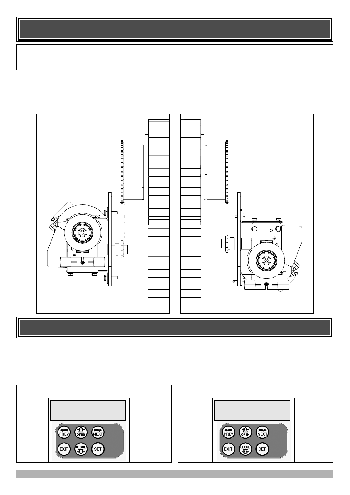
MOUNTING THE DRIVE UNIT
The mounting plate holes are slotted for fine adjustment of the
output gear position. Follow the procedure below to ensure final
adjustments can be made later.
1. Determine on which side of the door the opener is to be
mounted.
2. Install manual chain guide as required.
3. Mount the base plate to door bracket either by welding in
place or using M12 hex bolts, washers and nuts.
4. Position opener and secure with M10 fasteners.
5. Mount drive sprocket on shaft in line with door drive gear.
6. Shorten drive chain as required and fit around drive gears.
7. Feed manual chain through guide and over pulley.
8. Shorten chain as required and fix ends to make a loop.
FIG. 4
FIG. 3
Door Drive Gear
Drive Chain
Manual Chain Guide
Mounting Plate
8
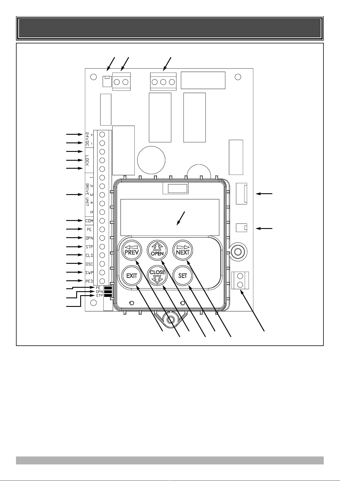
CONTROL BOARD LAYOUT
1 & 2. 24VDC output for powering accessories 3A(max)
3. Lock relay output N/C contact
4. Lock relay output COM contact
5. Lock relay output N/O contact
6. Drive unit connections
7. COM terminal for inputs terminals 8..14
8. P.E N/C input terminal
9. OPN N/C input terminal
10. STP N/C input terminal
11. CLS N/O input terminal
12. OSC N/O input terminal
13. SWP N/O input terminal
14. PED N/O input terminal
15. PE input jumper (remove when 8 is used)
16. OPN input jumper (remove when 9 is used)
17. STP Input Jumper (remove when 10 is used)
18. Console Exit Button
19. Console Previous Button
20. Console Down/Close Button
21. Console Up/Open Button
22. Console SET Button
23. Console Next Button
24. Antenna Connector
25. Console Display
26. Motor Speed Connector
27. Programmer Interface Connector
28. Motor Control Connector
29. 24V AC Power Supply
30. Light Module Interface Connector
1
2
3
4
5
6
7
8
9
10
11
12
13
14
15
16
17
18 20 22 24
19 21 23
25
27
26
30 29 28 FIG. 5
9
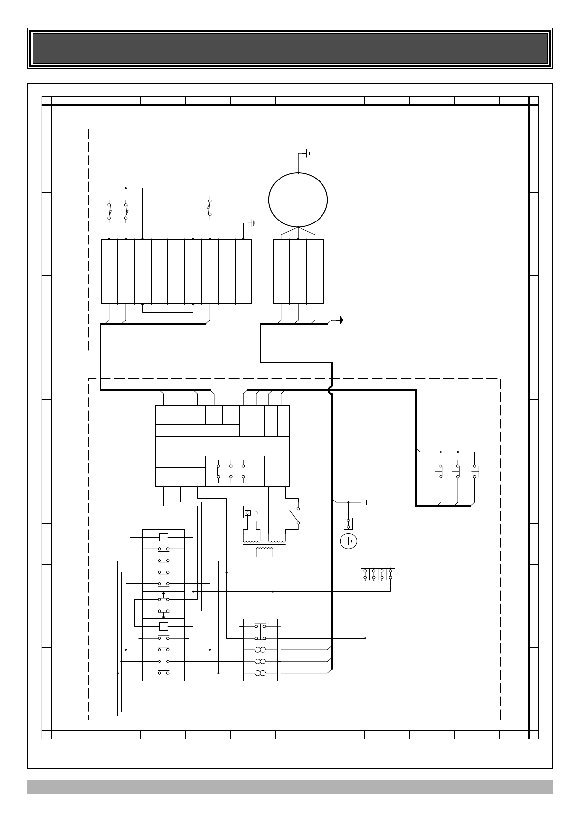
WIRING DIAGRAM THREE PHASE - LEFT HAND
0
0
1
1
2
2
3
3
4
4
5
5
6
6
7
7
8
8
9
9
10
10
11
11
12
12
13
13
14
14
AA
B B
C C
D D
E E
F F
G G
H H
I I
J J
U1
CB-14
T1
CLOSE OPEN
LOGIC CONTROL UNIT
CRTS-3-1 ATA
12V/2A
N
L1
L2
L3
96
98
2T1
4T2
6T3
95
97
OPEN
CLOSE
STOP
C
O
M
K2
TC11
K4
TCL-1
K1
TC11
K3
THR13
(1.4A-2.2A)
set 2A
J1
J2
SW1
SW2
SW3
NOTE: 1.Wiring as shown are for left hand instal-
lation.
2.SW4 two position key switch.
OFF ON
SW4
S3(INTLK)
COM
S1(CLS)
S2(OPN)
DRIVE UNIT
LIMITS
CLUTCH
INTERLOCK
SWITCH
J1
S1
S2
S3
3
4
1
BLUE
M
T
R
S
2T1
4T2
6T3
J2
12
11
10
9
8
7
6
S3(INTLK)
BLACK
BROWN
BLUE
BLACK
D
R
I
V
E
U
N
I
T
1
2
3
4
5
PWR
OPN
CLS
M
O
T
O
R
24Vac
COM
OPN
STP
CLS
PE
OPN
STP
JUMPERS
3
1
2
B
L
A
C
K
N/C
N/C
5N/C
4EARTHING
J2
1L1
3L2
5L3
A1
2T1
4T2
6T3
A2
1314
1L1
3L2
5L3
A1
2T1
4T2
6T3
A2
1314
9192
0102
ATA-MOTOR
THREE-PHASE
1HP, 415V

10
WIRING DIAGRAM THREE PHASE - RIGHT HAND
0
0
1
1
2
2
3
3
4
4
5
5
6
6
7
7
8
8
9
9
10
10
11
11
12
12
13
13
14
14
AA
B B
C C
D D
E E
F F
G G
H H
I I
J J
U1
CB-14
T1
CLOSE OPEN
LOGIC CONTROL UNIT
CRTS-3-1 ATA
12V/2A
N
L1
L2
L3
96
98
2T1
4T2
6T3
95
97
OPEN
CLOSE
STOP
C
O
M
K2
TC11
K4
TCL-1
K1
TC11
K3
THR13
(1.4A-2.2A)
set 2A
J1
J2
SW1
SW2
SW3
NOTE: 1.Wiring as shown are for right hand instal-
lation.
2.SW4 two position key switch.
OFF ON
SW4
S3(INTLK)
COM
S1(CLS)
S2(OPN)
DRIVE UNIT
LIMITS
CLUTCH
INTERLOCK
SWITCH
J1
S1
S2
S3
3
4
1
BLUE
M
T
R
S
2T1
4T2
6T3
J2
12
11
10
9
8
7
6
S3(INTLK)
BLACK
BROWN
BLUE
BLACK
D
R
I
V
E
U
N
I
T
1
2
3
4
5
PWR
OPN
CLS
M
O
T
O
R
24Vac
COM
OPN
STP
CLS
PE
OPN
STP
JUMPERS
3
1
2
B
L
A
C
K
N/C
N/C
5N/C
4EARTHING
J2
1L1
3L2
5L3
A1
2T1
4T2
6T3
A2
1314
1L1
3L2
5L3
A1
2T1
4T2
6T3
A2
1314
9192
0102
ATA-MOTOR
THREE-PHASE
1HP, 415V
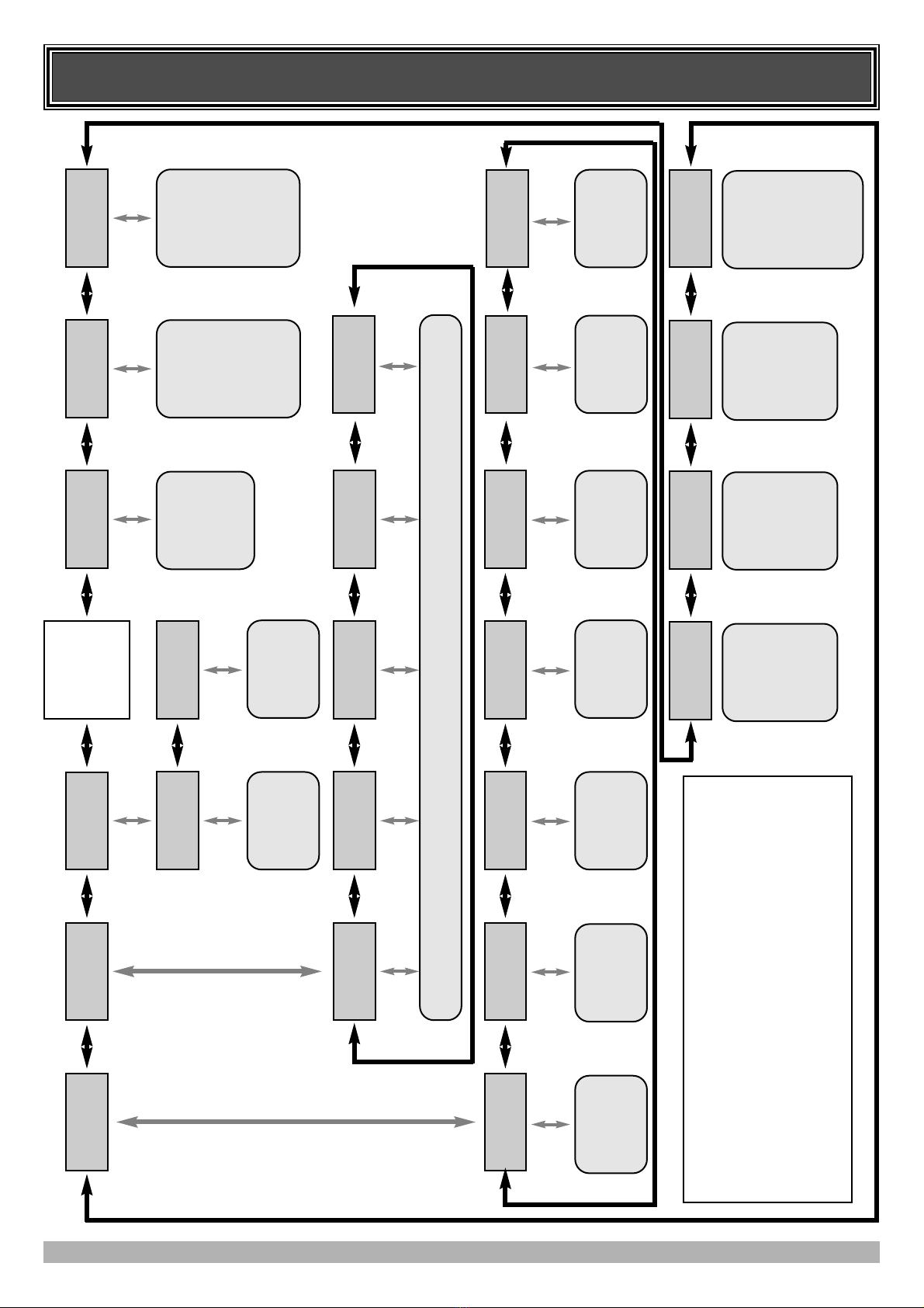
MENU STRUCTURE
11
MENU 8
Diagnostics
MENU 9
Memory Tools
MENU 10
Travel Limits
MENU 1
Code Transmitter
MENU 2
Obstruct Margins
MENU 3
Auto-Close Times
MENU 10.1
Set Door Travel
MENU 10.2
Set Pedestrian
MENU 9.1
CLR Control?
MENU 9.2
CLR Tx’ers?
MENU 9.3
Backup Tx’ers?
MENU 9.4
Restore Tx’ers?
MENU 8.1
Test Inputs
MENU 8.2
Test Tx’ers
MENU 8.3
Display History
MENU 8.4
Memory Usage
MENU 8.5
Service Counter
MENU 4
Lock Times
MENU 5
Light Times
MENU 6
Motor Settings
MENU 7
Operating Modes
MAIN SCREEN
(Door Status
& Information)
Code/Edit
Transmitter
Procedure.
See Page 21.
Parameter List
1. CLS Margin
2. OPN Margin
Etc
EDIT NOT
AVAILABLE.
Parameter List
1. STD Autoclose
2. P.E. Autoclose
3.
Ped’n
Autoclose
4. P.E.
Ped’n
Autoclose
See Page 17.
Travel Limit
Setup Procedure.
See Page 13.
Ped’n Position
Setup Procedure
See Page 15
Memory Reset / Reload Operations See 27.
Control Input
Status Display.
See Page 26.
Transmitter
Testing
See Page 26.
Event History
Display.
See Page 26.
Memory Usage
See Page 26.
Periodic Service
Cycle Counter
See Page 27.
Parameter List
1. Open Lock Time
2. Close Lock Time
3. Pre-Opn Lock Time
4. Pre-Cls Lock Time.
See Page 18.
Parameter List
1. On After Cycle Time
2. On Before Opn Time
3.On Before Cls Time
See Page 18.
Parameter List
1. Full Speed %
2. Min Speed %
3. Cycle Timeout
See Page 16.
Parameter List
1. PE Input Response
2. Ped Input Response
3. Remote Code Enable
4. Activity Report
ETC
See Page 19.
Notes
1. Move Left/Right using PREV/NEXT Buttons.
2. Move Up/Down using EXIT/SET Buttons.
3. System will automatically return to the main screen after 30
secs if a menu screen is displayed and no buttons are pressed.
4. Pressing EXIT when in MENU 1 - MENU 10 will return to
MAIN SCREEN.
MENU 9.5
Import Labels?
MENU 8.6
Counters
Cycle and event
Counter
See Page 27.
MENU 8.7
Installation
Installation
Parameters
See Page 27.
12
INITIAL ELECTRICAL INSTALLATION
CAUTION:
CABLES WHICH HAVE A GREEN/YELLOW COLOURED INSULATION ARE FOR
EARTHING PURPOSES ONLY. NEVER USE THESE CABLES FOR ANY OTHER PURPOSE.
STEP 1. INSTALLING ANTENNA
If the installation requires remote transmitters, an external anten-
na is required. Mount the antenna as high as possible for optimal
reception. Do not cut the coaxial cable.
STEP 2. SELECTING LEFT OR RIGHT HAND
INSTALLATION.
Using the figure below, place the motor connector for each drive
unit so as to reflect the side of the doorway that it is installed.
POWERING UP THE DRIVE UNIT
Connect to power. The controller will go through a startup
sequence displaying the STARTUP SCREEN which indicates the
controller type and firmware version.
After a short delay the MAIN SCREEN will be displayed. If this
is the first time the controller has been used the MAIN SCREEN
should indicate that the limits are not set. If the display shows that
an input is active then rectify the situation before continuing with
the procedure for setting the travel limits for the door.
Limits
Not
Set!
PPrreessss
<<>>
ttoo
AAcccceessss
MMEENNUUSS
MAIN SCREEN
A.T.A
CB14
Firmware
#.##
STARTUP SCREEN
STEP 3 - Selecting Left/Right Hand installation
Left Hand Right Hand
FIG. 8 FIG. 9
FIG. 10 FIG. 11

SETTING TRAVEL LIMITS
13
This section shows how to set the travel limits. The procedure can be partly completed using a transmitter. In order to use a
transmitter it must first have at least one of its buttons coded to the gate controller. The function assigned to the transmitter's buttons
is of no concern here as the buttons are temporally assigned to OPEN, CLOSE and SET.
Note: The limit setting procedure can be aborted at anytime by pressing EXIT.
Are
Motor
L/R
Connections
Ok?
PRESS
Motor
Encoder
Mode
O
PRESS
MENU
10.1
Set
Door
Travel
PRESS
FIG. 12
FIG. 13
FIG. 14
Note: Door should be moved manually to half open position.
STEP 1. NAVIGATING TO “SET DOOR TRAVEL MENU”
1. Press PREV to navigate to the Menu 10 (Fig. 12).
2. Press SET to display MENU 10.1.
3. Press SET again to enter the limit setting procedure.
STEP 2. SETTING THE LEFT/RIGHT CONNECTOR
1. Confirm motor connection is set for correct side (Fig. 13).
2. Press SET to confirm.
STEP 3. SELECTING MOTOR ENCODER MODE
The motor encoder is used to determine motor load and relative
position to the travel limits..
1. Press OPEN or CLOSE until “Off” is displayed.
2. Press SET to continue (Fig. 14).
ff
PRESS
SETTING TRAVEL LIMITS
14
//\\\\//To
CLS
Limit,
Adjust,
SET
PRESS
OR
PRESS
//\\\\//To
OPN
Limit,
Adjust,
SET
PRESS
PRESS
FIG. 15
FIG. 17
OR
FIG. 16
GREEN OPEN
LIMIT CAM
RED CLOSE
LIMIT CAM
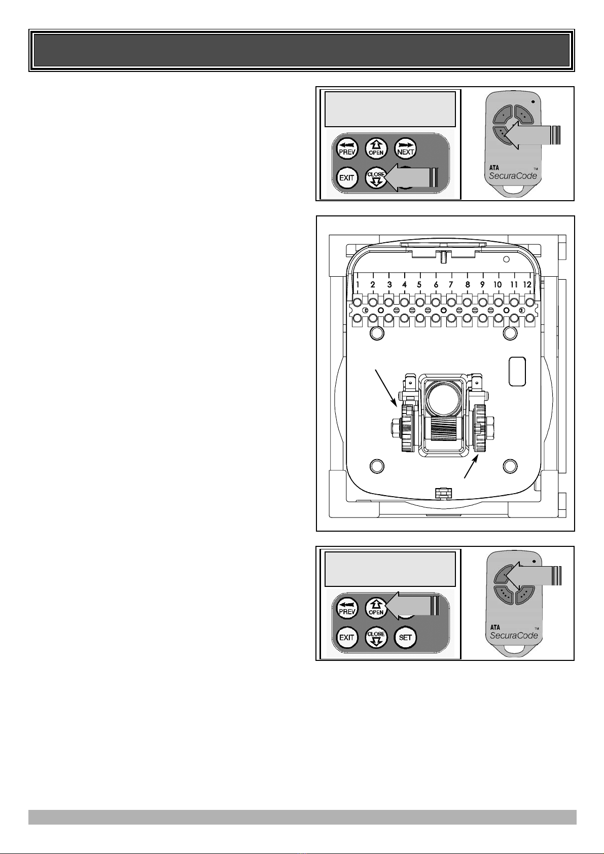
STEP 4. SETTING CLOSE TRAVEL LIMIT
1. Press CLOSE to move door to the desired CLOSE LIMIT.
(Or Press button 4 on transmitter) (Fig. 15).
2. Rotate red CLOSE limit cam until switch is activated
(Fig. 16).
Note: If the limit cam engages before the door reaches the required
position, adjust the cam back to allow for additional door travel.
3. Press SET to record the CLOSE LIMIT.
(Or press button 2 on Transmitter).
Note: Limit will not be accepted unless the door is driven in the
close direction.
STEP 5. SETTING OPEN TRAVEL LIMIT
1. Press OPEN to move door to the desired OPEN LIMIT.
(Or Press button 1 on transmitter) (Fig. 17).
2. Rotate green OPEN limit cam until switch is activated.
Note: If the limit cam engages before the door reaches the required
position, adjust the cam back to allow for additional door travel.
3. Press SET to record the OPEN LIMIT.
(Or press button 2 on Transmitter).
Note: Limit will not be accepted unless the door is driven in the
open direction.
AUTOMATIC LIMIT ADJUSTMENT AND LOAD PROFILE
After a brief pause the controller will automatically close and open
the door several times to learn the normal load profile of the door
and the normal travel times. When the setup is complete the MAIN
SCREEN will be displayed with the door shown to be Closed. The
door can now be used.
Note: Do not press transmitter during limit adjustment process.
PEDESTRIAN ACCESS POSITION
After completing the above procedure the Pedestrian access
position is automatically set to a position which is in the middle of
the gate travel. The position can be manually set by following the
SETTING PEDESTRIAN POSITION procedure.
ERRORS DURING SETTING OF TRAVEL LIMIT
During the above procedure many error checks are preformed. If an
error is detected a message will be displayed indicating the error.
15
SETTING PEDESTRIAN POSITION
FOR OPENERS WITHOUT AN ENCODER FITTED.
Note: Before setting the pedestrian access position the door must
be in the fully closed position. As with the Setting Travel
Limit procedure, a transmitter can be used to complete the
pedestrian position setting procedure.
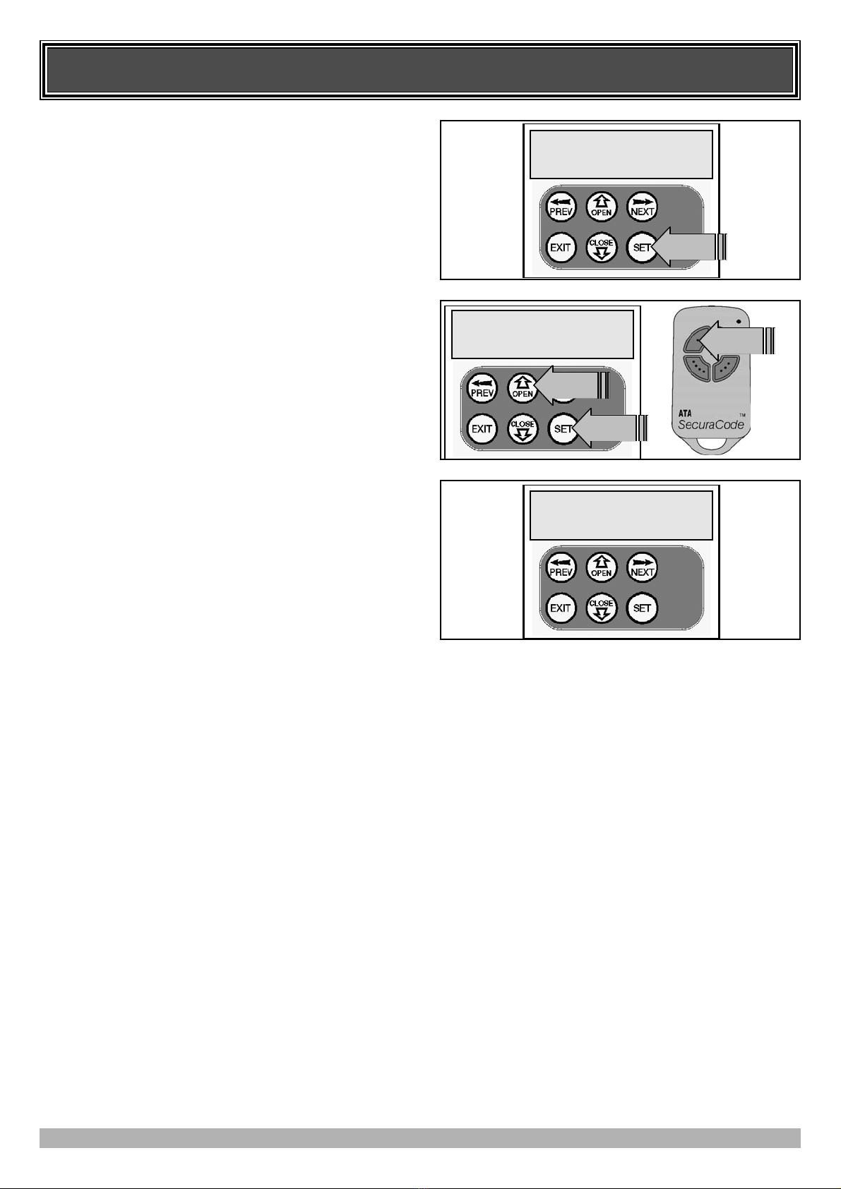
STEP 1. NAVIGATING TO “SET PEDESTRIAN MENU”
1. Press PREV to navigate to the Menu 10 (Fig. 18).
2. Press SET - MENU 10.1 is displayed.
3. Press NEXT to go to MENU 10.2.
4. Press SET to enter Set Pedestrian procedure.
STEP 2. SETTING PEDESTRIAN POSITION
1. Press OPEN to move gate to desired pedestrian access position.
(Or press button 1 on transmitter) (Fig. 19).
2. Press SET to record position.
(Or press button 2 on transmitter).
STEP 3. PEDESTRIAN POSITION SET
The controller will return to the MAIN SCREEN with the gate
status shown as being in pedestrian access mode (Fig. 20).
MENU
10.2
Set
Pedestrian
PRESS
//\\\\//to
Pedestrian
Position,
SET
PRESS
Ped’n
Access
PPrreessss
<<>>
ttoo
AAcccceessss
MMEENNUUSS
PRESS
PRESS
FIG. 18
OR
FIG. 19
FIG. 20

16
This section describes the standard operation of the control board
with the factory set default values.
MOTOR CONTROL.
The controller drives the motor in the appropriate direction as
instructed by the control inputs. Once a cycle is started the motor
will continue to travel until:
1.The controller is instructed to stop by a control input.
2.The motor's travel limit is reached.
3.A motor is obstructed, overloaded or stalls
When the control inputs instruct the control board to change the
motor direction, the controller turns off the motor, waits for the
motor to stop and then starts the motor in the other direction.
MOTOR OBSTRUCTION DETECTION
This feature is only enabled if an encoder if fitted to the
opener and the encoder option is selected during the travel
limit setup.
If a motor is obstructed while opening, the motor is stopped. If a
motor is obstructed while closing, the motor is stopped and then
reversed to the open position. Obstruction detection is achieved
by monitoring the motor's speed and comparing it to the “normal”
speed profile. If the speed of the motor falls below the “normal”
by the MARGIN RPM setting, then the motor is said to be
obstructed. In addition to the normal motor obstruction detection,
motor overload, stall detection and excessive travel time detection
is provided to protect the door and opener.
MOTOR SPEED CONTROL (VFD required)
The motor's speed is controlled using a frequency output
connected to a VFD or inverter. When a motor is started its speed
is ramped up to the selected open/close speed % parameter and
then ramped down as the travel limit is approached so as to come
to a gentle stop.
LOCK RELEASE OUTPUT
The lock release output is configured to pulse for 0.5 seconds at
the start of each cycle. The output is turned on at the same time
the motor is started.
COURTESY LIGHT
With the addition of a module which plugs into the control board,
the control board will control a courtesy light. The light is
normally used to illuminate the driveway etc. The light will be
turned on each time the door is activated (day or night) and
automatically turned off 1 minute after the drive cycle has
finished.The light can also be activated and deactivated by
pressing a transmitter button assigned the LGT function.
OPEN/STOP/CLOSE (OSC) INPUT
(Activated by OSC terminal with N/O switch or by transmitter
button with OSC function assigned)
If the door is stopped the OSC input will cause the door to move
in the opposite direction to that last travelled. If the door is
moving the OSC input will cause the door to stop.
PEDESTRIAN ACCESS (PED) FUNCTION
(Activated by PED terminal with N/O switch or by transmitter
button with PED Function assigned).
The pedestrian access operation partly opens the door allow
pedestrian access but prevent vehicle access. The position the
door is driven to is automatically set to halfway during setting of
the travel limits, but can be manually adjusted. Pedestrian access
mode is entered when the input is activated and the door is in the
closed position. If the door is not in the pedestrian access mode,
the PED input will stop the door, if moving, or close the door, if
stopped. While in pedestrian access mode, the pedestrian access
position temporally becomes the open limit for the door. The PED
input then acts with an OSC type function. The pedestrian access
mode is exited when the door is closed or when another input is
activated.
CLOSE (CLS) INPUT
(Activated by CLS terminal with N/O switch, by transmitter
button with CLS function assigned or by console’s CLOSE
button).
Activating the CLS input will cause the door to close. Holding the
input active will prevent opening.
SWIPE (SWP) INPUT
(Activated by SWP terminal with N/O switch or by transmitter
button with SWP function assigned).
Activating the the SWP input will cause the door to be opened. If
the terminal input is held it will prevent the door being closed.
The swipe input also effects P.E TRIGGERED AUTO CLOSE.
OPEN (OPN) INPUT
(Activated by OPN terminal with N/C switch, by transmitter
button with OPN function assigned or by console’s OPEN button)
Activating the OPN input will cause the door to open. Holding the
input will prevent closing.
STOP (STP) INPUT
(Activated by STP terminal with N/C switch, by transmitter
button with STP function assigned or by console’s EXIT button)
Activating the STP input while the door is moving will cause the
door to be stopped. If the STP terminal is held it will prevent the
door from being moved.
PHOTOELECTRIC SAFETY BEAM (P.E) INPUT
(Activated by PE terminal with N/C switch)
When the P.E input is active, the door is prevented from being
closed. If the P.E input is triggered while the door is closing, the
controller will stop the motors and then open the door. The P.E
input has no effect while the door is opening.
VACATION MODE
The controller supports a vacation mode where remote control
access is disabled. The mode is activated by pressing a
transmitter button with the VAC function assigned until the con-
sole displays that vacation mode is enabled (approx. 5 seconds).
When activated any transmitter button which is assigned VAC
will be ignored. To turn the Vacation mode off simple press a
transmitter button with the VAC function assigned (Only requires
a brief activation.) Vacation mode can also be turned on or off
manually by editing the VACATION MODE parameter.
DESCRIPTION OF STANDARD OPERATION

17
CONTROL BOARD ADJUSTMENTS
The opener’s standard operation can be altered by editing various parameters. This section describes the parameters and the
effect they have. Use the VIEWING AND EDITING PARAMETER PROCEDURE on Page 20 to make changes.
STANDARD AUTO-CLOSE
This mode is selected by entering a non-zero time for the STD
Autoclose parameter. When selected the door will auto-close after
being fully opened (except when the door has reversed to the open
position after a motor obstruction or overload). Countdown is
suspended by: the P.E, OPN or SWP input being active. The
countdown is aborted if the STP input is activated. If the door is
already open and the OPN or the SWP input is activated then the
countdown will start.
P.E TRIGGERED AUTO-CLOSE
This mode is selected by entering a non-zero time for the “P.E
Autoclose” parameter. This mode is used to auto-close the door
but only after a vehicle have passed through the doorway and
triggered the P.E input. The swipe input can be used to clear the
P.E triggered status so that the P.E input must be activated again
before the countdown will start. As with the other P.E modes the
STP input will abort countdown and the OPN and SWP inputs
will restart the countdown if the door is OPEN.
PEDESTRIAN ACCESS AUTO-CLOSE
This mode is selected by entering a non-zero time for the “Ped’n
A/C” parameter. When selected the door will auto-close after
being opened for pedestrian access unless it was following a
reverse from an obstruction.
P.E TRIGGERED PEDESTRIAN AUTO-CLOSE
This mode is selected by entering a non-zero time for the “P.E
Ped’n A/C” parameter. This mode is the same as the P.E
triggered auto-close mode but it only operates during pedestrian
access. As the SWP input is not available during pedestrian
access, the PED input can be configured to act in a SWP mode by
setting the “PED I/P = PED SWIPE MODE” parameter to ON.
AUTO-CLOSE AFTER OBSTRUCTION
Two parameters are provided to enable the auto-close feature to
be activated after obstructions. Normally the auto-close feature is
not enabled after obstructions for safety reasons. A P.E beam must
be used for these features to be activated
The auto-close modes automatically close the door after it has been operated. To implement this, the controller starts a timer
once the door has reached its desired open position. The timer then counts down and when it expires the controller starts to
close the door. Details about the four auto-close modes follow. ATA strongly recommend using a PE Beam for added safety.
MENU 3 - AUTO-CLOSE TIMES
PARAMETER MIN MAX DEFAULT STEP UNIT MENU No.
STD AUTOCLOSE TIME
Sets and enables the standard auto-close time. 0.0 300.0 0.0 1.0 SEC 3
P.E AUTOCLOSE TIME
Sets and enables the P.E triggered auto-close time. 0.0 300.0 0.0 1.0 SEC 3
PEDESTRIAN AUTOCLOSE TIME
Sets and enables the Pedestrian auto-close time. 0.0 300.0 0.0 1.0 SEC 3
P.E PEDESTRIAN AUTOCLOSE TIME
Sets and enables the PE Pedestrian auto-close time. 0.0 300.0 0.0 1.0 SEC 3
AUTOCLOSE AFTER CLOSE OBSTRUCTION
Enables autoclose feature after close obstructions OFF ON OFF 3
AUTOCLOSE AFTER OPEN OBSTRUCTION
Enables autoclose feature after open obstructions OFF ON OFF 3

18
CONTROL BOARD ADJUSTMENTS
MOTOR SPEEDS
When speed ramping is enabled during the limit setup procedure,
the controller will ramp the motors speed up at the start of a cycle
and then down again at the end of the cycle prior to stopping at
the limit. The parameters for open and close speeds set the
respective motor speeds for the open and close cycles. The
minimum speed parameter sets the minumum speed output to the
motor at the start and end of ramping.
NOTE: Altering these parameters will cause the travel limits
to be cleared.
CYCLE TIMEOUT
Sets the maximum time a cycle can run past its normal cycle time
for before an obstruction is tripped.
MENU 4 - LOCK TIMES
MENU 5 - LIGHT TIMES
MENU 6 - MOTOR SETTINGS
With the addition of a relay module connected to the control
board, a light can be controlled. The time the light stays on, is
controlled by two timers. The first times the period the light is
activated for prior to a drive cycle. This is used to warn that door
movement is pending. The second times how long the light
remains on after a cycle. The parameters are shown below.
Lock output can be programmed for both hold and pulse
operation and can also be programmed to activate prior to the
door motor starting. The operation of the lock can be programmed
to behave differently on open cycle to that on close cycles.
PARAMETER MIN MAX DEFAULT STEP UNIT MENU No.
OPEN LOCK TIME
Set the time the lock is activated for on open cycles 0.0 HOLD 0.5 0.1 SEC 4
CLOSE LOCK TIME
Set the time the lock is activated for on close cycles 0.0 HOLD 0.5 0.1 SEC 4
PRE-OPEN LOCK TIME
Time the lock is activated for prior to opening. 0.0 25.5 0.0 0.1 SEC 4
PRE-CLOSE LOCK TIME
Time the lock is activated for prior to closing 0.0 25.5 0.0 0.1 SEC 4
PARAMETER MIN MAX DEFAULT STEP UNIT MENU No.
ON AFTER CYCLE LIGHT TIME
Time light remains on for after a cycle 0 255 60 1 SEC 5
ON BEFORE OPEN CYCLE LIGHT TIME
Minimum time light is activated for prior to opening 0 255 0 1 SEC 5
ON BEFORE CLOSE CYCLE LIGHT TIME
Minimum time light is activated for prior to closing 0 255 0 1 SEC 5
PARAMETER MIN MAX DEFAULT STEP UNIT MENU No.
CLOSE SPEED
Sets the motor speed for close cycles 1 100 100 1 % 6
OPEN SPEED
Sets the motor speed for open cycles 1 100 100 1 % 6
MIN SPEED
Minimum speed output to the motor 1 100 100 1 % 6
CYCLE TIMEOUT (NORM +)
Cycle overrun time permitted before obstruction. 0.1 25.5 2.0 0.1 Sec 6
19
CONTROL BOARD ADJUSTMENTS
MENU 7 - OPERATING MODES
P.E INPUT RESPONSE MODE
The P.E input can be configured to respond in one of three modes.
OPEN AND CLOSE CYCLES STOP
In this mode all cycles are prevented from being
completed or initiated when the P.E input is
active.
CLOSE CYCLES STOP
In this mode the P.E input has no effect when
opening but will stop the gate when closing.
REVERSES CLOSE CYCLES
In this mode the P.E input has no effect when
opening but will cause the gate to reverse if
activated when closing.
PED INPUT FUNCTION
The PED input can be configured to a SWIPE type input for
pedestrian access. This provides full functionality with the P.E
Triggered Pedestrian auto-close function.
REMOTE CODE
The controller supports the Remote Code Set feature. This
parameter can be used to disable the feature for security or
transmitter management reasons.
ACTIVITY REPORTS
This parameter enables activity report outputs. Contact ATA for
more details.
ACTIVITY REPORT ID
This parameter sets the ID of the controller that is sent with the
activity report. Contact ATA for more details.
VACATION MODE
Vacation mode can be turned on or off using this parameter.
BATTERY/SOLAR MODE
The controller can be instructed to turn off the battery backup
facilities so that the control board can be shut down without
having to disconnect the battery backup system.
PASSWORD PROTECTION
The password feature enables all parameters and configuration
settings to be protected unless a password is entered. When this
feature is turned on the user is requested to enter the desired pass-
word to be used. The password protection feature has a time-out
that expires after 60 seconds of inactivity. Alternately the user
may log out manually by pressing exit when the main screen is
displayed.
OPEN INPUT POLARITY
The OPN input is normally configured for N/C operation. This
parameter allows its operation to be changed to N/O.
PARAMETER MIN MAX DEFAULT STEP UNIT MENU No.
P.E INPUT RESPONSE MODE Sets the P.E response mode.
Options are OPEN and CLOSE cycles stop, Close cycles stop
or Close cycle reverse
OPN & CLS stop
CLS to stop
CLS to reverse
CLS to
reverse 7
PED INPUT = SWIPE MODE
Selects PED input functions as pedestrian access swipe input. OFF ON OFF 7
REMOTE CODE ENABLED
Selects remote transmitter coding function OFF ON ON 7
ACTIVITY REPORTS
Select report to be output OFF 255 OFF 1 7
ACTIVITY REPORT ID
Selects ID for controller, sent with activity report 0 65535 0 1 7
VACATION MODE
Selects vacation mode - disables remote control. OFF ON OFF 7
PASSWORD
Selects password protection for all changes. OFF ON ON 7
TX # GROUPING
Selects tx’er number group display format. OFF ON OFF 7
OPN INPUT N/O OPERATION
Selects operating polarity of OPN input OFF ON OFF 7
This section illustrates how to locate, view and adjust
parameters.
LOCATING PARAMETERS
Refer to MENU STRUCTURE on Page 9 or the preceding section
for CONTROL BOARD ADJUSTMENTS. Locate the required
parameter and note the MENU number. The example in (Fig. 21)
uses “CLOSE LOCK TIME” will be used as an example.
CHANGING SETTING
1. Press NEXT/PREV to navigate to the required menu.
2. Press SET to show sub menu.
3. Press NEXT/PREV to go to required submenu.
4. Press SET to enter edit mode.
5. Press UP/DOWN to change parameter setting.
Holding the button down causes the parameter’s value to
change rapidly. The longer the button is held the faster the
value changes.
6. Press SET to SAVE setting.
RELOAD DEFAULT SETTING
1. Press NEXT/PREV buttons to display LOAD DEFAULT
screen.
2. Press SET to load the default value.
RETURN TO MENU
If the parameter’s value is not to be changed, press EXIT to return
to sub menu. Press EXIT again to return to the MAIN SCREEN.
20
VIEWING AND EDITING PARAMETER
2: Close Lock
Time (SEC) 0.5
Exits Back to VIEW MODE
With No Changes Made.
Displays “Load Default?”
Screen, which gives the
option of loading the default
value.
Decrease Value
Increase Value
Saves New Value and Exits
Back to VIEW MODE
Displays “Load Default?” Screen,
which gives the option of loading
the default value.
Cursor Shown
2: Close Lock
Time (SEC) 0.5
Returns Back to Menu
Displays Previous Parameter in List
Displays Next Parameter in List
Parameter Number in List
Parameter Name
Parameter Value
Enter EDIT MODE
Enter EDIT MODE
VIEW MODE (No Cursor)
EDIT MODE (Cursor shown) FIG. 22
FIG. 21
This manual suits for next models
1
Table of contents
Popular Door Opening System manuals by other brands


GEZE
GEZE Powerturn Series Wiring diagram

Richards-Wilcox
Richards-Wilcox DYNA-HOIST DC Series installation manual

LCN
LCN 4110EDA instruction sheet

Mantion
Mantion SLID'UP 2500 Instructions for assembly

Henderson
Henderson MARATHON FDK1 Fitting instructions

LCN
LCN 4412 HSA Installation instructions and operators manual

Glutz
Glutz SD-L F 9365 Series Mounting and operating instructions

D+H
D+H VCD 204 Original instructions

SUGATSUNE
SUGATSUNE LAMP FD50-H installation manual

CAME
CAME PB2100 manual

Raynor
Raynor ControlHoist 2.0 OPTIMA Installation instructions and user guide

Assa Abloy
Assa Abloy Norton 7500H Series installation instructions