Contents
1.
Technical Parameters..........................................................................................................................1
2.
Components...................................................................................................................................2
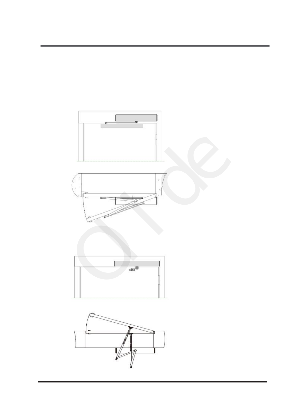
Installations.................................................................................................................................... 3
3.1
Installation example......................................................................................................................... 3
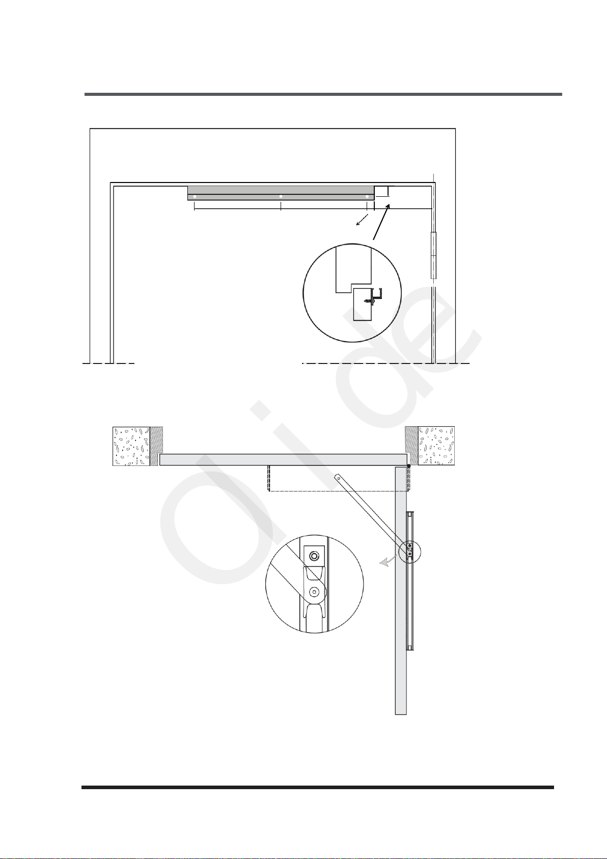
3.2
Installation of base plate...................................................................................................................4
3.3
Installation of pull arm..................................................................................................................... 5
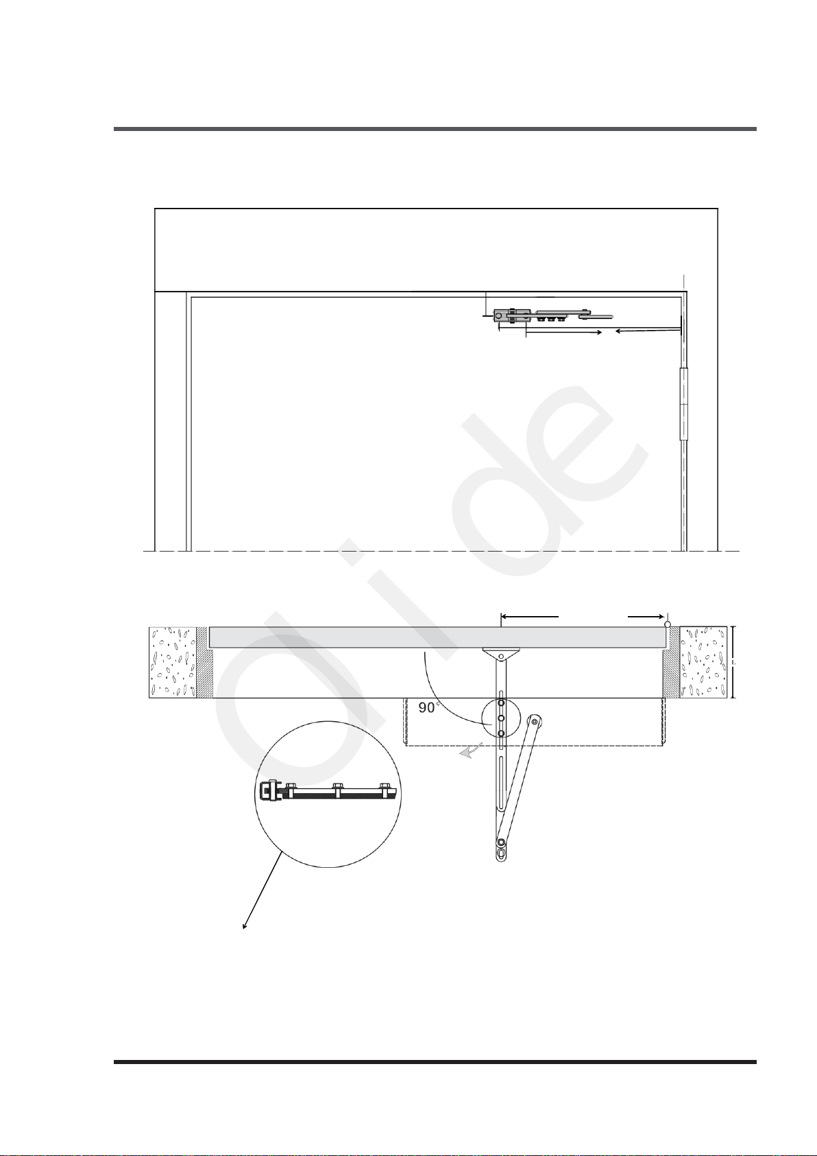
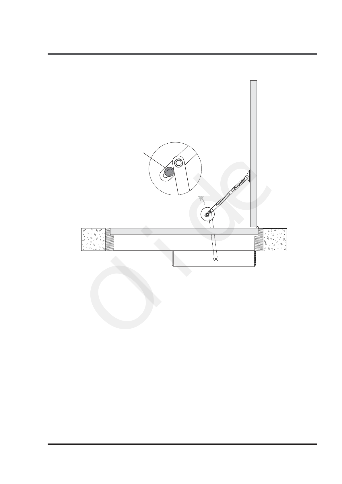
3.4
Installation of push arm.................................................................................................................... 6
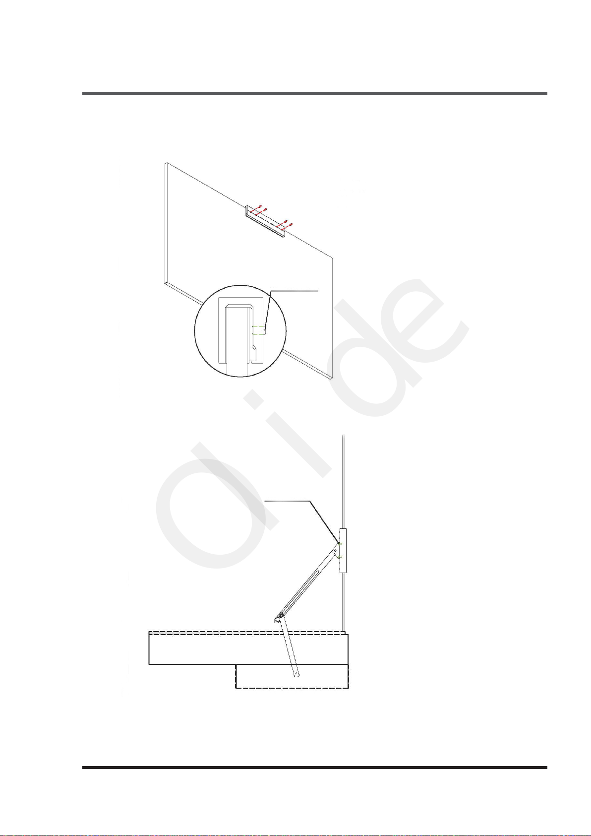
3.5 Installation of Push arm for frameless glass door............................................................................. 8
3.7
Installation of operation system................................................................................................... ......9
3.9
Connection the operation system with the pull arm......................................................................... 10
3.10
Connection the operation system with the push arm....................................................................... 11
4.
Electrical Connections........................................................................................................................12
Control panel details...........................................................................................................................12
4.1
Connections with a keypad .........................................................................................................12
4.2
Connections with a microwave sensor ............................................................................................. 13
4.3
Connections with PIR sensors ....................................................................................................
13
4.4
Connections for a safety motion top scan .........................................................................................13
4.5
Connections for push buttons.............................................................................................................. 14
4.8
Connections for magnetic locks ............................................................................................................15
4.9
Connections for electric locks.........................................................................................................15
4.10
Connection with the touchless hand sensor switches ........................................................................... 15
4.15
Double door synchronous settings..................................................................................................18
4.16 Wireless push buttons settings........................................................................................................19
4.17 Remote control settings..............................................................................................................20
5.
Parameters Adjustment...........................................................................................................................21
5.1
hand programmer instruction.....................................................................................................................21
5.2
adjustment steps........................................................................................................................................22
6.
Trouble Shooting.....................................................................................................................................23
4.6
Connections for wiring disabled push buttons....................................................................................14
4.7
Connections for wireless handicapped push buttons .............................................................................14
3.6 Installation of Pull arm for frameless glass door.............................................................................. 8
3.8
Installation of cover...................................................................................................................... ......9
4.11
Connecting to wireless touchless sensor switch Olide-508,Olide-512 .................................................16
4.12
Connecting to wired touchless sensor switch Olide-514,Olide-513 and Olide-513.............................. 16
4.13
Connecting to wired touchless sensor switch Olide-514,Olide-513 and Olide-513N........................... 16
4.14
Connecting to wired narrow handicap push button 515......................................................................... 17