Installation Instructions
WARNING
HAZARDOUS VOLTAGE CAN SHOCK AND CAUSE SEVERE INJURY
Disconnect power before making any electrical connections
or performing maintenance.
1 Closer
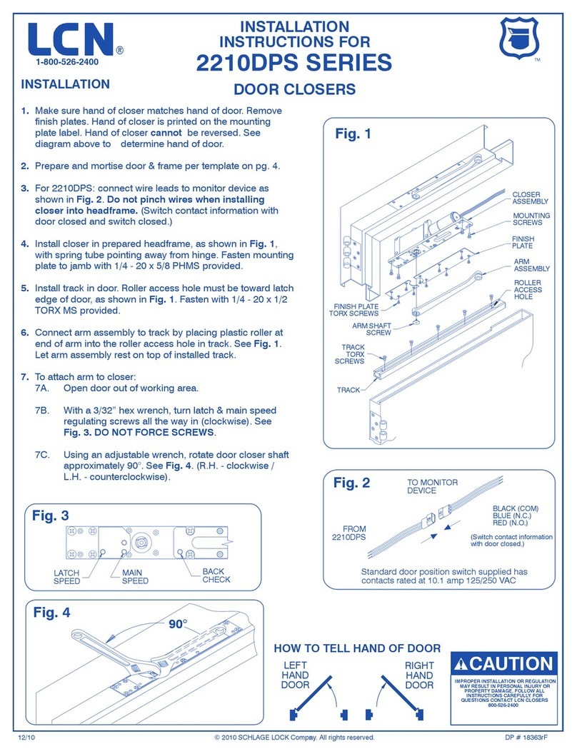
The closer is handed at the factory, and marked with an “R” or “L”
on top of the packing nut. The hand of the closer must match the
handing of the door (see the door handing diagram on page 1).
2 Input Voltage
Input voltage supplied to the door frame must be 24V. Determine
whether the wiring will be concealed or surface-run, and follow the
remaining instructions carefully.
3 Wiring
3a For concealed wiring:
See Figure 2 on page 3.
1. Prepare the frame with the proper template on page 6. Be sure
all of the holes are dimensioned correctly before drilling and
tapping.
2. Assemble the conduit connector provided to the exible
conduit, then attache to the hole in the mounting plate.
3. Secure the mounting plate to the frame with the screws
provided.
3b For surface wiring:
See Figure 3 on page 3.
LNOTE: Remove the knockout in the top of the cover.
1. Prepare the frame with the proper template on page 6. Be sure
all of the holes are dimensioned correctly before drilling and
tapping.
2. Secure the mounting plate to the frame with the screws
provided.
3. Attach the surface run Z\x” EMT conduit to the hole in the
bracket on the mounting plate. Be sure the conduit is securely
attached to the bracket.
4 Wiring Connections
Make your wiring connections at this time. Connect two black wires
to the 24V input voltage. The green wire MUST be connected to an
earth ground. See Figures 2 & 3 on page 3.
5 Arm Shaft
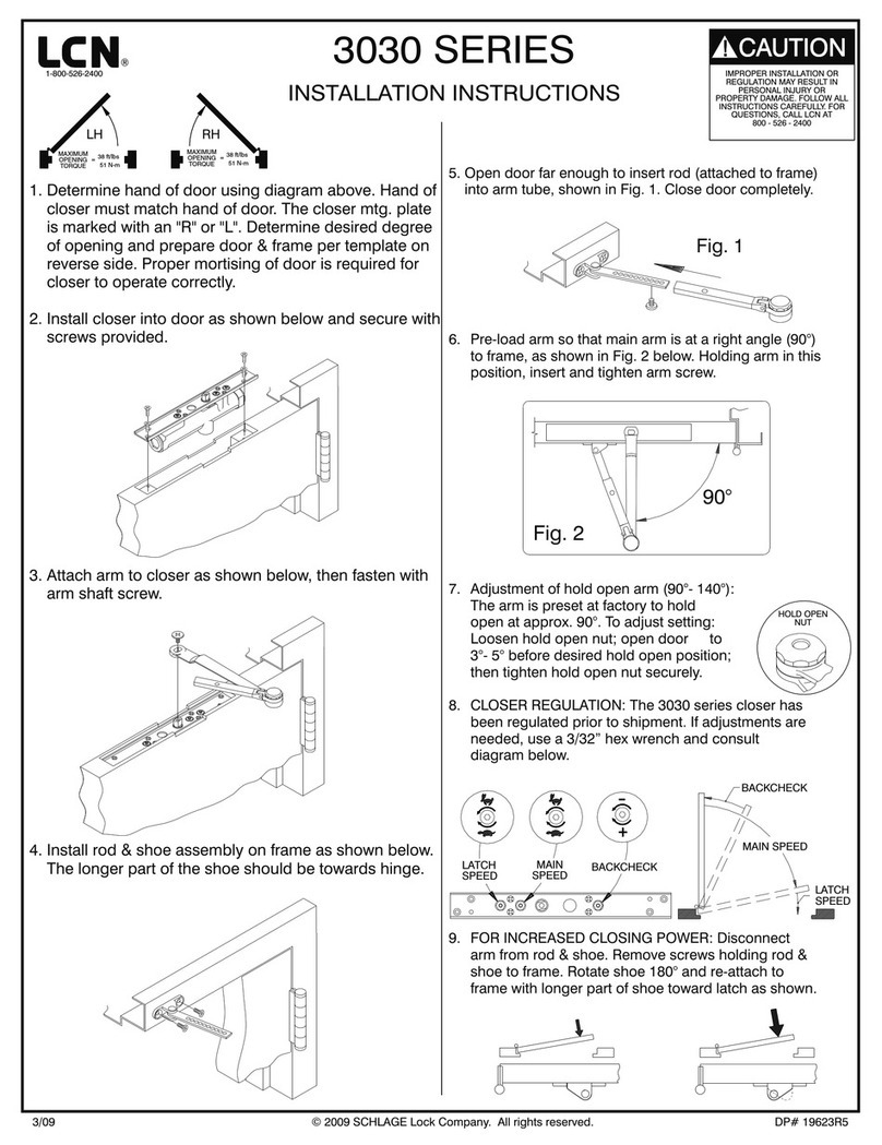
Place the main arm on the closer shaft, 90° to the closer body, and
secure with the arm shaft screw.
6 Track Setup
Attach the rod & shoe to the door (per the template on page 5) with
the screws provided.
7 Set Screw
Open the door partway, insert the rod into the forearm, then close
the door. With the main arm at a right angle (90°) to the door, insert
the arm set screw, and tighten securely.
8 Spring Power Adjustment
See Figure 1 for the spring power adjustment diagram. To adjust
the spring power, use a B\cx” allen wrench provided to turn the
spring adjustment nut clockwise or counterclockwise the required
number of turns to match the door width in the spring adjustment
chart on page 6. DO NOT exceed 7 turns clockwise or 8 turns
counterclockwise.
9 Closing Speed Regulation
The closing speed regulation is preset at the factory. Normally
no adjustment is required. If adjustment is needed or desired,
adjust the main speed and latch speed by turning the proper
regulating screw for each (see Figure 1) clockwise to slow or
counterclockwise to increase the speed. Do not allow the door to
slam into the frame. A “normal” closing time from a 90° position is
5 to 7 seconds, equally divided between the main and latch speed.
When adjusting the backcheck, use the least amount of force
necessary to sufciently slow the swing of the door. To adjust the
backcheck, turn the regulating screw clockwise to increase the
amount of force, or counterclockwise to reduce the amount of force.
DO NOT USE AN ABRUPT BACKCHECK SETTING OR EXPECT
THE CLOSER TO ACT AS A STOP!
10 Electrical Checkout
Perform the electrical checkout on page 4 before installing the
closer cover.
CAUTION
Improper installation or regulation may result in personal
injury or property damage! Follow all instructions
carefully.
For questions, call LCN at
1-877-671-7011.


