Copyright © 2007, 2014 Yale Security Inc., an ASSA ABLOY Group company. All rights reserved.
Reproduction in whole or in part without the express written permission of Yale Security Inc. is prohibited. 80-9377-1204-020 (04-14)
5
ASSA ABLOY
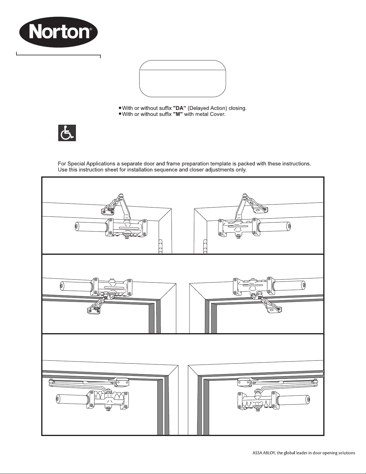
Installation
Instructions Parallel Arm
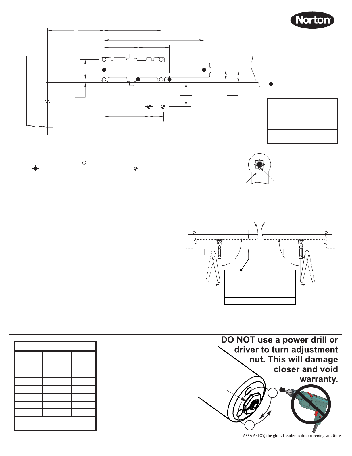
Template
To 100°
101° to 130°
131° to 150°
151° to 180°
Opening
8-3/4
7-1/4
6-1/4
5-1/4
222
184
159
133
inches mm
9-1/4
7-3/4
6-3/4
5-3/4
235
197
171
146
inches mm
Dimension A Dimension B
Installation Sequence
A6-3/4
(171.5)
2-3/8
(60.3)
1/4
(6)
4
(101.6)
4-3/4
(120.7)
2-7/8
(73) 5/16
(7.9)
1-1/2
(48)
12-3/4
(323.9)
Do Not Scale Drawing
Left Hand Door Shown
Dimensions are in inches (mm).
7788 Dropplate
Mounting Hole Only
C
LHinge or Pivot
B
3/8
(10) 2-3/4
(69.9)
½
(13)
2
(50.8)
• Make closer adjustments, if required, using information below
and on Page 6, then install closer cover.
• Select angle of opening and use dimensions shown in template
and chart to locate 4 holes on door for closer body (or 4
holes for optional 7788 dropplate) and 4 holes on
underside of frame for soffit plate.
For applications that are different from above, a separate
template will be supplied for door and frame preparation.
• Prepare door and frame for fasteners using "Preparation for
Fasteners" chart, Figure 2, Page 2.
• Fasten optional 7788 dropplate to door, only if it is required for
the door conditions.
• Install closer body with tube end away from hinge, with valves:
Down for Left Hand door
UP for Right Hand door.
• Fasten soffit plate to frame.
• Install arm shoe (with holder loop)onto soffit plate with hold open
nut:
UP for Right Hand door
Down for Left Hand door
• Secure with screw assembly from screw pack.
• Install main arm onto closer pinion shaft using information below
and above right illustration. The one flat corner of the square
shaft “Pinion Flat”, must be aligned with the corner mark on
arm:
Hold Open Nut
UP
Hold Open Nut
DOWN
Right Hand Door
Left Hand Door
1-1/2
(38)
Door Swing
2° Typ.
Arm Preload
Valves Down Valves Up
• Open door slightly to slide connecting rod into holder loop unit.
Close door and pull arm away from door face so elbow is 1-1/2”
(38mm) off of door face. Tighten set screw in holder loop.
L
R
Y
S
Z
L
R
Y
S
Z
Pinion Flat
Arm Mark
Left Hand Right Hand
Power Adjustment Chart
Maximum
Interior
Door Size
Maximum
Exterior
Door Size
26 / (660)
30 / (762)
36 / (914)
42 / (1067)
NOTE: Maximum of 16-1/2 turns
(360°) of Power Adjustment Nut.
48 / (1219)
30 / (762)
34 / (864)
38 / (965)
48 / (1219)
54 / (1372)
inches / (mm)
inches / (mm)
Turns
from
Zero
Install closer per instructions
with the proper pre-load
applied to the arm then
adjust spring power. The
power adjustment will not
work properly if the closer
spring is not pre-loaded.
To increase power, use 11/16"
wrench to turn power
adjustment nut clockwise.
To decrease power, turn nut
counter clockwise.
Arm mark “Y” for Right Hand door
Arm mark “Z” for Left Hand door
This requires that the pinion shaft be rotated approximately 50
degrees to get correct alignment .
• Secure with hex washerhead main arm screw.
"Spring Power
Adjustment Nut" +
-
7
9
12-1/2
14-1/2
16-1/2