manuals.online logo
Brands
  1. Home
  2. •
  3. Brands
  4. •
  5. Chamberlain
  6. •
  7. Door Opening System
  8. •
  9. Chamberlain T User manual

Chamberlain T User manual

Model H
ADDENDUM
Carwash Operator with Logic 2.0 Circuit
Models:T, GT, GH, H and J
This addendum is to be used in conjunction with the owner’s manual included with this
operator. Refer to the manual for all mounting and wiring instructions. The carwash mod-
ification includes a TEFC motor Watertight/Oiltight Control Enclosure watertight/oiltight 3-
button control station and nickel-plated chain in lieu of all standard components of the oper-
ator.
1. Refer to page 2 & 3 of addendum for Electrical Box Replacement Parts.
2. Refer to page 4 of addendum for suggested control and power wiring connec-
tions for NEMA 4 applications
FOR ALL OTHER INSTALLATION INSTRUCTIONS REFER TO OWNERS MANUAL
SHIPPED WITH OPERATOR.
REPAIR PARTS KITS – ELECTRICAL BOX
LOGIC CONTROL (VER. 2.0)
Below are replacement electrical box kits available for your operator. For replacement of electrical box components be sure to
match model number of your unit to kit number below to ensure proper voltage requirements. For all other part operator part
ordering information refer to owners manual supplied with operator.
Complete Electrical Box Replacement Kits
To order a complete electrical box replacement kit, add a
K- prefix to the model number of your operator. For exam-
ple:
CGH5011L = K-CGH5011L
K72-18282 & K72-18281 (GT) LIMIT SHAFT ASSY. KITS
Item
L1
L2
L3
L6
L7
L8
L9
Description
SHAFT, LIMIT CARWASH
LIMIT NUT
SPRKT. 48B18 X 3/8"
SPRKT. 48B9 X 3/8" (CGT ONLY)
PHOTO CUP
WASHER, SHIM
ROLL PIN, 1/8" DIA.
E-RING, 3/8"
Qty
1
2
2
1
1
1
7
1
P/N
11-17648
13-10024
15-48B18AXX
15-48B9A1
158A0068
80-10026
86-RP04-100
87-E-038
COMPLETE ELECTRICAL BOX KITS
Item
1
2
3
4
5
6
7
8
9
10
11
12
13
14
15
16
17
Description
CONTACTOR (See Variable Components)
PANEL,CARWASH
FLANGE BEARING, 3/8"
BEARING SEAL, 3/8"
NEOPRENE GASKET
DEPRESS PLATE
TRANSFORMER (See Variable Components)
INTERLOCK SWITCH (CH, CJ, CGH ONLY)
OVERLOAD (See Variable Components)
STANDOFF
RADIO BLOCK
ENCLOSURE, CARWASH
STANDOFF, PCB
SCREW, #10-32 HEX SLOTTED
FLATWASHER, #10
KIT, PCB ASSEMBLY
KIT, SENSOR ASSEMBLY
Qty
1
1
2
2
2
2
1
1
1
4
1
1
9
4
4
1
1
P/N
03-8024K
10-17647
12-10481
12-10483
13-10516
18-10036
21-XXXX
23-10916
25-XXXX
31-12378
42-10040
44-1210-4XD
75-13705
82-HS10-06
85-FW-10
K79-13433
K79-15016
ITEM
3
4
11
PART NO.
21-14182
21-5460
21-5575
25-2006
25-2008
25-2010
25-2015
25-2020
25-10296
25-11107
25-13840
03-8024K
DESCRIPTION
Transformer, 115 Volts
Transformer, 460 Volts
Transformer, 575 Volts
Overload, 6 Amp
Overload, 8 Amp
Overload 10 Amp
Overload 15 Amp
Overload 20 Amp
Overload 2.8-4.4 Amp
Overload 5.2-8.0 Amp
Overload 2.0-3.0 Amp
K-Line Contactor
5011L2
5021L2
5023L2
5043L2
5025L2
5038L2
7511L2
7521L2
7523L2
7543L2
7525L2
7538L2
1011L2
1021L2
1023L2
1043L2
1025L2
1038L2
1511L2
1521L2
1523L2
1543L2
1525L2
1538L2
2023L2
2043L2
2038L2
3023L2
3043L2
3038L2
3353L2
5053L2
7553L2
1053L2
Qty
1
1
3
3
3
2
4
2
2
2
Item
S1
S2
S3
S4
S5
S6
S7
S8
S9
S10
P/N
10-10476
10-10478
10-12553
10-12806
23-10041
82-PX04-12
82-PX04-20
82-PX06-16
84-LH-06
18-10036
Description
DEPRESS PLATE
AUX. L/S MT'G BRACKET
NUT PLATE
BACKUP PLATE
LIMIT SWITCH
SCREW, #4-40 PAN HEAD
SCREW, #6-32 PAN HEAD
LOCKNUT, #6-32
SPRING
K75-12514 LIMIT SWITCH ASSEMBLY KIT
VARIABLE COMPONENT KITS
2
HOW TO ORDER REPAIR PARTS
OUR LARGE SERVICE ORGANIZATION
SPANS AMERICA
INSTALLATION AND SERVICE INFORMATION
ARE AVAILABLE 6 DAYS A WEEK
CALL OUR TOLL FREE NUMBER - 1-800-528-2806
HOURS 7:00 TO 3:30 p.m. (Mountain Std.Time)
MONDAY Through SATURDAY
ILLUSTRATED PARTS – ELECTRICAL BOX
L2
L8
L7
L9
S5
S6
S2
14
17
17
L3
15
8
3
5
4
L7 L9
L6
L1
3
c2000, The Chamberlain Group, Inc.
All rights Reserved
01-17781A
RECOMMENDED POWER AND CONTROL CONNECTIONS
DISCONNECT POWER AT THE FUSE BOX BEFORE
PROCEEDING.
OPERATOR MUST BE PROPERLY GROUNDED AND
CONNECTED IN ACCORDANCE WITH LOCAL ELEC-
TRICAL CODES. NOTE: THE OPERATOR SHOULD
BE ON A SEPARATE FUSED LINE OF ADEQUATE
CAPACITY.
ALL ELECTRICAL CONNECTIONS MUST BE MADE
BY A QUALIFIED INDIVIDUAL.
Before installing power wiring or control stations be sure to follow all specifications and warn-
ings described below. Failure to do so may result in severe injury to persons and/or damage to
operator.
For best protection against the environment follow directions below for recommended specifi-
cations for power and control wiring connections.
SUGGESTED CONDUIT & FITTINGS
Liquidtight Flexible Nonmetallic Conduit is permitted
for use in both exposed and concealed areas and for
electrical systems that require flexibility and protection
from vapors, liquids or solids.
LFNC conduit should be used for Liquidtight environ-
ments as stated by NE A guidelines.
All conduit and conduit fittings should be marked as
“Liquidtight”, conduit and fittings marked “Raintight” or
“Wet Locations” are not to be automatically consid-
ered liquidtight.
NOTE: Select all conduit and conduit connectors
based on local code and application of job.
CONDUIT & FITTING PREPARATION
The most efficient assembly of a liquidtight conduit
and fitting system can be achieved, and optimum per-
formance ensured, by adherence to simple conduit
preparation and assembly techniques:
1. Square off ends of conduit by cutting the end of the
conduit squarely using a hacksaw or similar tool, con-
duit manufacturers sometimes offer cutting jigs for this
purpose.
2. Fully insert conduit flush with the fitting end stop.
3. Secure conduit to fitting. A compression gland nut,
when supplied as part of a fitting, will typically achieve
maximum securement.
4. Ensure conduit jacket is not cut or ripped in any
location along its surface.
NOTE: For conduit preparation, always follow the
conduit manufacturers instructions.
ATTACHMENT TO ENCLOSURE
1. Select proper fitting entry hole to be placed in
enclosure and punch through using drill or tool sup-
plied by manufacturer.
2. Slide threaded body into fitting hole in enclosure.
3. Insert gasketing around threaded area and secure
in place with nut supplied. (Refer to manufacturer
specifications for proper torque requirements).
NOTE: For fitting attachments, always follow the
manufacturers instructions.
ANY MAINTENANCE TO THE OPERATOR OR IN THE
AREA NEAR THE OPERATOR MUST NOT BE PER-
FORMED UNTIL DISCONNECTINGTHE ELECTRICAL
POWER VIA, THE MAIN DISCONNECT SWITCH.
UPON COMPLETION OF MAINTENANCE THE AREA
MUST BE CLEARED AND SECURED, AT THAT TIME
THE UNIT MAY BE RETURNED TO SERVICE.

Other manuals for T

8

This manual suits for next models

4

Other Chamberlain Door Opening System manuals
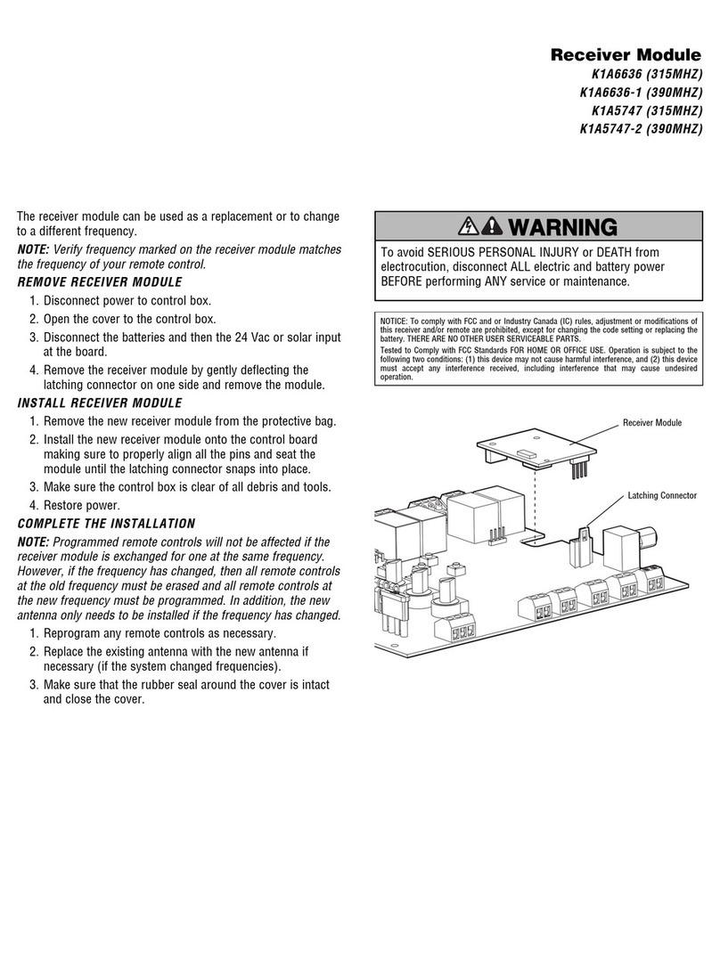
Chamberlain DDO8900W User manual

Chamberlain

Chamberlain DDO8900W User manual

Chamberlain LiftMaster PROFESSIONAL 76LM User manual

Chamberlain

Chamberlain LiftMaster PROFESSIONAL 76LM User manual

Chamberlain T User manual

Chamberlain

Chamberlain T User manual

Chamberlain 050DCRJWFMC User manual

Chamberlain

Chamberlain 050DCRJWFMC User manual

Chamberlain GSD series User manual

Chamberlain

Chamberlain GSD series User manual

Chamberlain 9747E Series User manual

Chamberlain

Chamberlain 9747E Series User manual

Chamberlain CPS-U User manual

Chamberlain

Chamberlain CPS-U User manual

Chamberlain MyQ Garage User manual

Chamberlain

Chamberlain MyQ Garage User manual

Chamberlain Liftmaster MT5011 User manual

Chamberlain

Chamberlain Liftmaster MT5011 User manual

Chamberlain HCTDCU User manual

Chamberlain

Chamberlain HCTDCU User manual

Chamberlain LJ8900W User manual

Chamberlain

Chamberlain LJ8900W User manual

Chamberlain ELITE Series User manual

Chamberlain

Chamberlain ELITE Series User manual

Chamberlain T User manual

Chamberlain

Chamberlain T User manual

Chamberlain ATS 2113X 1/2 HP User manual

Chamberlain

Chamberlain ATS 2113X 1/2 HP User manual

Chamberlain Motorlift ML700 User manual

Chamberlain

Chamberlain Motorlift ML700 User manual

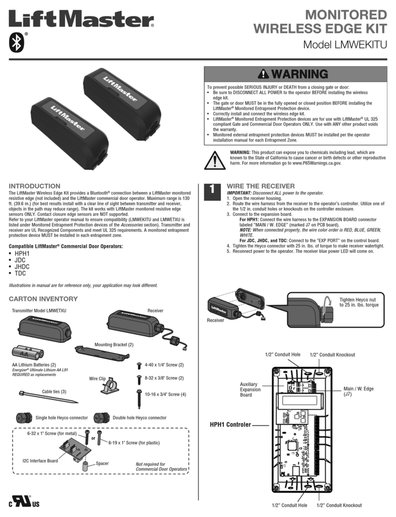
Chamberlain LMWEKITU User manual

Chamberlain

Chamberlain LMWEKITU User manual

Chamberlain 883LM User manual

Chamberlain

Chamberlain 883LM User manual

Chamberlain LiftMaster Premium 8355 User manual

Chamberlain

Chamberlain LiftMaster Premium 8355 User manual

Chamberlain 878MAX User manual

Chamberlain

Chamberlain 878MAX User manual

Chamberlain K1A6636 User manual

Chamberlain

Chamberlain K1A6636 User manual

Chamberlain LiftMaster Professional RDO800 Series User manual

Chamberlain

Chamberlain LiftMaster Professional RDO800 Series User manual

Chamberlain K001D8398-1 User manual

Chamberlain

Chamberlain K001D8398-1 User manual

Chamberlain DKK Series User manual

Chamberlain

Chamberlain DKK Series User manual
Chamberlain LA400DC User manual

Chamberlain

Chamberlain LA400DC User manual

Popular Door Opening System manuals by other brands

RIB VERTIGO Wi-Fi manual

RIB

RIB VERTIGO Wi-Fi manual

Assa Abloy Norton 8000H Series installation instructions

Assa Abloy

Assa Abloy Norton 8000H Series installation instructions

LCN 2210DPS Series installation instructions

LCN

LCN 2210DPS Series installation instructions

JNF IN.81.203 Assembly

JNF

JNF IN.81.203 Assembly

Raynor ControlHoist CMT Installation instructions manual

Raynor

Raynor ControlHoist CMT Installation instructions manual

Dorma ED 100 Mounting and Commissioning instructions

Dorma

Dorma ED 100 Mounting and Commissioning instructions

Command access MLRK1 Series installation instructions

Command access

Command access MLRK1 Series installation instructions

Dormakaba TS 98 XEA Mounting instructions

Dormakaba

Dormakaba TS 98 XEA Mounting instructions

Eco TS-41 Assembly instruction

Eco

Eco TS-41 Assembly instruction

Assa Abloy Norton CloserPlus CLP8101 installation instructions

Assa Abloy

Assa Abloy Norton CloserPlus CLP8101 installation instructions

KROME 950002 Installation instruction

KROME

KROME 950002 Installation instruction

Dormakaba RTS88 installation instructions

Dormakaba

Dormakaba RTS88 installation instructions

Relcross 9130 installation instructions

Relcross

Relcross 9130 installation instructions

DSC PG8949 installation instructions

DSC

DSC PG8949 installation instructions

Entrematic EM PSW250 User's manual and operating instructions

Entrematic

Entrematic EM PSW250 User's manual and operating instructions

Green Brook DW030A quick start guide

Green Brook

Green Brook DW030A quick start guide

Entrematic Ditec DAS801LOK installation manual

Entrematic

Entrematic Ditec DAS801LOK installation manual

Assa Abloy DC140 installation instructions

Assa Abloy

Assa Abloy DC140 installation instructions

manuals.online logo
manuals.online logoBrands
  • About & Mission
  • Contact us
  • Privacy Policy
  • Terms and Conditions

Copyright 2025 Manuals.Online. All Rights Reserved.