SUGATSUNE LAMP FD50-H User manual

1
FOR YOUR SAFETY AND CORRECT INSTALLATION
Thank you for using our product. Before installation, please read this manual thoroughly to ensure correct installation.
Please keep this manual at hand for future reference.
ABOUT THE PRODUCT
●
This is a parts set for sliding door system for residential &
commercial use.
●Built in soft closer enables two-way soft closing movement
in both direction.
●
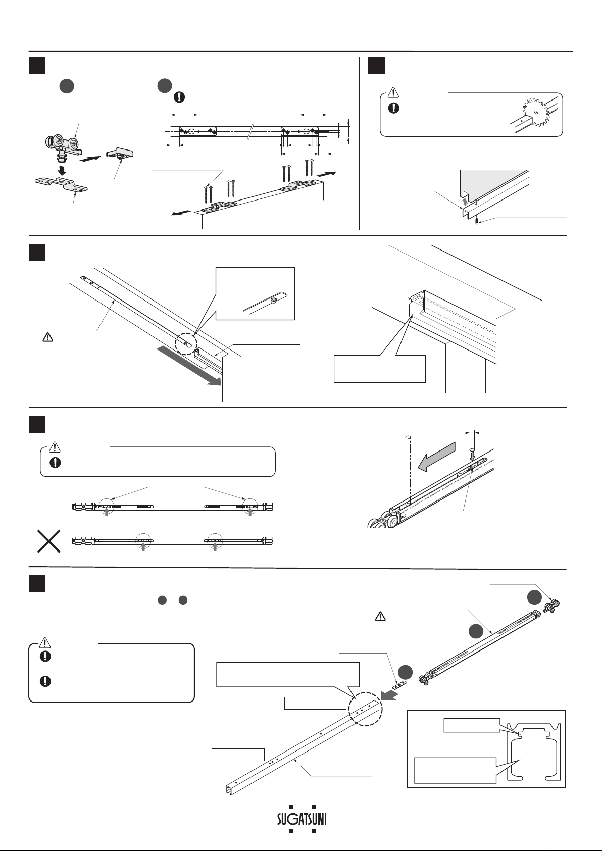
Two sections of track for easy maintenance after installing.
SPECIFICATIONS
・
The closing speed of the soft closing type door may change
depending on the ambient temperature, operating method or
installation quality.
・
Recommended ambient temperature range is 5 to 40䉝
※1When using a light weight door, you may feel the resistance of the
soft closer when opening the door.
Door height Max. 2400 mm 2401 - 2700 mm
Door width 774 -1500 mm 800 -1500 mm
Min. Door thickness 30 mm
Max. Door weight 50 ※1kg/door
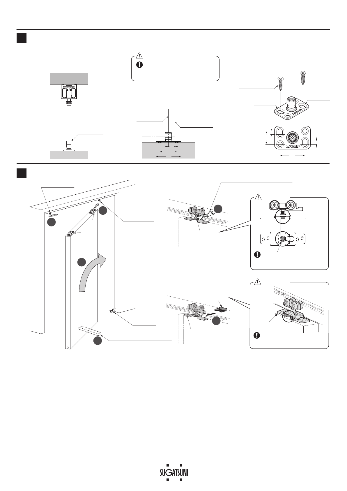
Vertical adjustment 3 mm upward, 4 mm downward
Warning :
Caution : If not followed, injury or damage may result.
Prohibited
Warning
Caution Required
Meaning of symbols
If not followed, death or serious injury may result.
Do not use this product for any other purpose, or with doors that are outside the specifications of this manual.
Do not disassemble or modify any parts other than those described in this document.
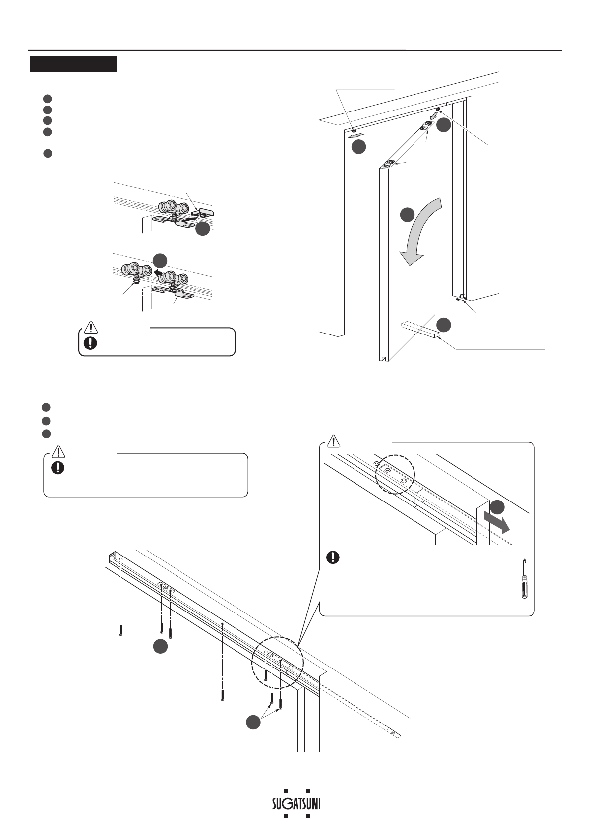
This product should be installed by a qualified person in accordance with this manual. If it is not installed correctly, the door
may fall and cause injury.
Provide a frame that can withstand the weight and impact of opening and closing the door. Be sure to use the specified
screws and tighten them securely. If the mounting strength is insufficient, the door may fall and cause injury.
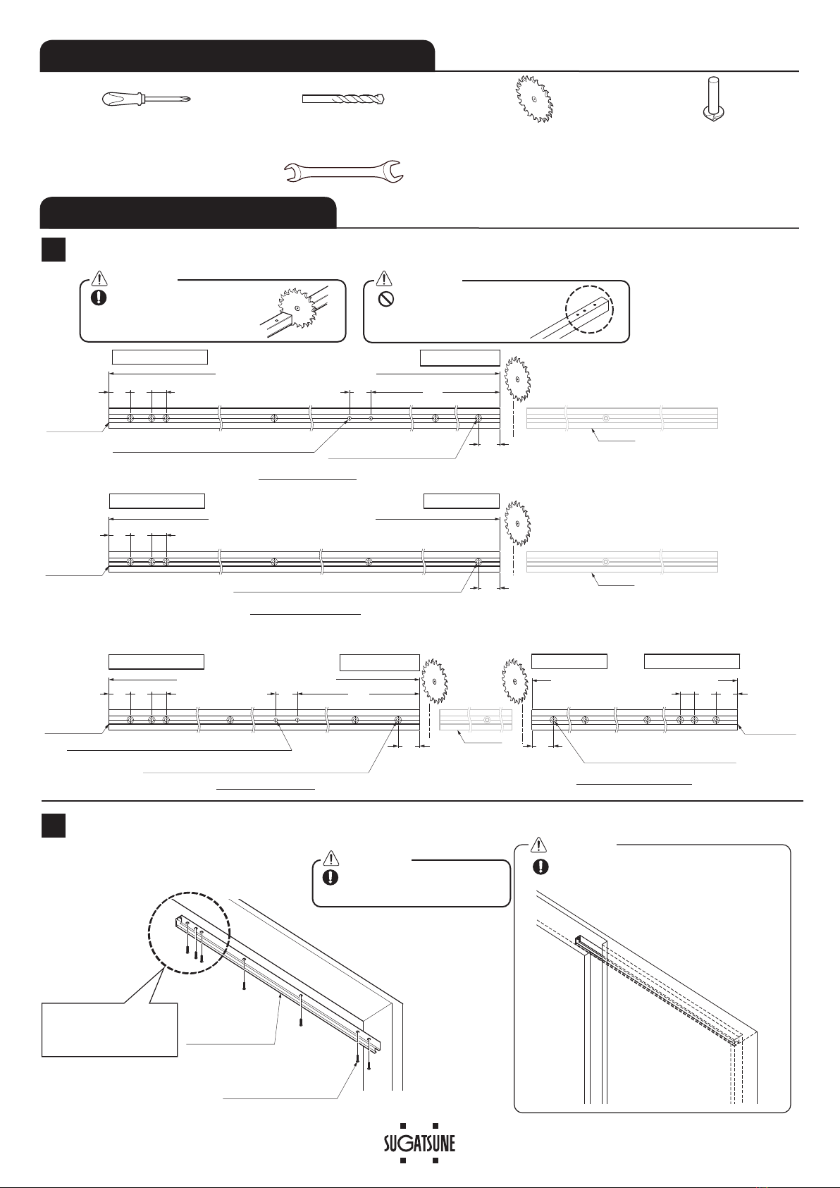
If cutting any parts, make sure to remove any burrs before installation. Also check the upper track for any left-over burrs or
scraps and remove these.
Install the product with two people (in the case of one person, there is a risk of damaging components).
Follow the specified dimensions, specifications, and alignment of the door and frame. Warping, tilting or twisting of the
frame or door may cause failure.
This product is a part for architectural fittings. After installation, please check the function and safety of the final product.
Please inform the end user how to use the product safely.
Make sure to check the screws for slack at regular intervals (one month from first usage, half a year, and then one time
every year is recommended).
When installing the “pocket door”, make an “easy-maintenance” structure.
For example, use a removable panel.
Door
Door pocket
FD50-H SLIDING DOOR SYSTEM Installation Manual
(Surface mount rollerType for Pocket Door, with Two-way Soft Close)
Part No.FD50DHCMP-PD

2
Margin
DN
:LGWKRIGRRUSRFNHW5S: 5:í5R:í'1
Track length (opened area): Lo
= RoW 7UDFNOHQJWKGRRUSRFNHW/S 5:í5R:
30
10
Opening width: RW
44
Connecting position
of Upper tracks
Trailing edge at fully
closed position
Leading edge at
fully opened position
30 460
264 30
Full opened position
Connecting position
of Upper tracks
Trigger of Leading
edge side
Trigger of Trailing edge side
Overlap: 10
〈In case of No Margin (DN = 0) : 20〉
Closed position
In case of No Margin (DN = 0), the front part of the door
pocket must be detachable for door hanging.
16
28
30
20±4
15
10 17
Door thickness Dt = Min. 30
Min. 7
Min. 7
28
2 ×C5 (Min.)
15
17
Min. Opening width
of door pocket
= Door thickness : Dt +14
13 2
7 6
54 1
Door
Door vertical
adjustment range
4
4
Door process dimensions
Leading
edge Trailing
edge
Front face of door pocket
Door width: DW = RoW +DN +10
〈In case of No Margin (DN = 0) : RoW +20 〉
No. ① ②③④⑤⑥⑦
Name Open area track Door pocket
track
Soft closer
(two-way) Front trigger Pocket trigger Upper roller Floor guide Door guide
track
Order code
$YDLODEOHZLWKYDULRXVOHQJWKDQG¿QLVKHV
250-022-902 250-029-707 250-029-738 250-022-901 250-029-718 250-019-971
Part No. FD50-TRP
FD50-WRM-DSC
FD50-TRGPF
FD50-TRGPB-MB
FD50-WRM FD50-BGR18
FD30-HBRT1500SIL
Parts
1pc 1pc 1pc 1 pc 1 pc
Hole pitch : 250 mm
Pitch end : 30 mm
1pc
Accessories
Countersunk head tapping screws 4 ×40
(Q'ty depends on the hole location)
Pan head tapping
screws
4 ×45 4 pcs
Countersunk head
tapping screws
4 ×40 2 pcs
Countersunk head
tapping screws
4 ×40 2 pcs
Pan head tapping
screws
4 ×45 4 pcs
Countersunk head
tapping screws
4 ×20 4 pcs
Recommended screw
: Countersunk head
tapping screws 4 ×20
Optional parts
№⑧
Name Spanner
wrench
Part No. FD30-FSP
Parts
Nominal designation
10 mm, 12 mm
×
FD50 Below parts which are packed with
soft closer② are not needed for this application.
Trigger mount jigTrigger : 2 pcs
Countersunk head tapping
screws 4×30 D6 : 4 pcs
INSTALLATION DRAWING (EXAMPLE)
The example shows the sliding door when the leading edge (at the fully opened position) is aligned with the connecting
position of the upper tracks. To shift the connecting position towards the trailing edge, see page 9.
COMPONENT PARTS

3
Open area track
Door pocket track
Door pocket Track
Open area track
Track length for open area : Lo
30 249
30
Track length for door pocket : Lp
30
Track length for door pocket : Lp
30
Track length for open area : Lo
30 249
30
30
20
When cutting from a long track (1860 mm, 2760 mm & 3960 mm)
Leading edge
Trailing edge
Connecting side
Connecting side
Track end to
be connected
Track end to
be connected
Track end to
be connected
2 ×I5
Process holes for Trigger (leading edge).
I
5.2
I
9.6 CSK
Process holes for track mounting.
I5.2 I9.6 CSK
Process holes for track mounting.
Track end to
be connected
I5.2 I9.6 CSK
Process holes for track mounting.
2×I5
Process holes for Trigger (leading edge).
No use
No use
No use
I5.2 I9.6 CSK
Process holes for track mounting.
30 30 20 30 30
30 20
30 30 20
Leading edge
Connecting side Trailing edge Connecting side
1Cutting and Drilling on Upper Track
2Installing Door Pocket Track
①
Door pocket track
Countersunk head
tapping screws 4 ×40
(in cluded in ①)
The end which has three
countersunk holes must
face the center.
When cutting, reinforce the
track to prevent deformation
at the cut section.
Do not cut the track on the
side with three holes.
Caution Caution
Remove any dirt or aluminum
chips from the track.
Caution Install the cover panel onto the door
pocket after mounting the track.
Caution
INSTALLATION PROCEDURE
TOOLS REQUIRED FOR INSTALLATION
・Philips head driver #2 ・Drill bit for metal:I5・Machine or tool for
cutting aluminum alloy
・Drill bit for metal
(for I9.6 countersunk hole)
・Spanner (Nominal designation 10 mm, max. 6 mm thickness)

4
5Installing Pocket Trigger
6Verification Before Installing Soft Closer
Insert this end with
the pin.
Correct set position
Trigger catcher
Correct set position
Improper set position
OK
3Installing Bracket 4
7Inserting Parts into Open Area Track.
Insert the parts in order from to .
You can insert the parts smoothly from the connecting end which has no burrs.
1 3
Leading edge
Connecting side
⑤
Upper roller
3
②Soft Closer
2
③
Front trigger
1
The edge which has three countersunk
holes is the end to be connected.
①
Open area track
①
Door pocket track
Trigger catcher
(Red colored part)
Slot for soft closer
/roller
Slot for trigger
Pay attention to the
direction.
(Red colored Part)
Insert the pocket trigger
until it reaches the end
of the track.
④
Pocket trigger
Installation of Door Guide Track
Bracket
⑦Door guide track
Holder
Upper roller
②⑤
Pan head tapping
screw4×45
(provided)
Pay attention to setting the direction of the bracket. The
open part of the bracket should face in the outside direction.
80
25
80
6
72
110 25
121225
2
1
Disassemble Fastening
Outside Outside
1Cut the track to the same length as the door width.
When cutting, reinforce
the track to prevent deformation
at the cut section.
2 Fasten the track with countersunk head tapping
screws 4 ×20 (not provided).
Countersunk head
tapping screws 4×20
(not provided)
Without verification the self closing feature may fail.
I6
If the triggerposition is wrong, pull back the
trigger catcher to the correct position using a
6 mm diameter round bar.
Caution
Caution
Remove any dirt or aluminum chips
from the track.
Tape around rollers and upper track
to prevent inserted parts from falling.
Caution
Pay attention to the
direction.

5
8Mounting of Open Area Track.
Align the track end to the end of the
door pocket track.
Pull out the pocket trigger from the
door pocket track, and insert it into the
open area track.
The end which has three countersunk
holes should be connected to door
pocket track.
Screw 4 ×40
(included in ①)
Screw 4 ×40
(included in ①)
Screw 4 ×40
(included in ③)
Screw 4 ×40
(included in ④)
Fasten the open area track and pocket trigger with provided screws in order of to .
Move rollers if they cover the fastening holes on the track.
1 5
After fastening the track, move rollers and check if there's any misalignment
or gap between the tracks.
【1】Connecting to door pocket track
【2】Fastening trigger and track
①
Door pocket track
①
Open area track
1
2
3
5
4
④
Pocket trigger
Remove any dirt or aluminum
chips from the track.
Overlap the two countersunk holes on
the pocket trigger and the two holes on
the open area track.
Deviation of the joint position makes
insertion of the trigger difficult.
When sliding the pocket trigger, use a
screwdriver.
The screwdriver may unexpectedly come
out and damage the track.
Scratches on the running track may cause
a noise of rollers during operation.
When tightening the ❶screws,
make sure that the both tracks
are aligned.
Be careful not to misalign the
tracks. Tighten the screws firmly.
OK
Caution
Caution
Caution
Caution Caution
Caution

6
9
10
Mounting of Floor Guide Temporarily
Hanging Door
Slotted hole
Slotted hole
The position of the model where
the margin occurs is shown in
the figure.
Position the floor guide below the
center of the upper track, so that it
is covered by the door when it is
opened and closed.
Front face of
door pocket Trailing edge at
closed position
30
10
44
2
4
1
3
5
4
30
16
4
⑥
Floor guide
6
Temporarily fasten through the
slotted holes with the provided
screws.
Ensure that hanger bolt head is in
straight as shown for proper fastening
of the holder.
Verify that the claw of the shaft
support holder catches the
opposite side of the holder.
⑧Spanner wrench(Optional parts)
Nominal designation 10 mm ,
max. 6 mm thickness
Hanger bolt
Bracket
Bracket
Holder
⑤Hanger bolt
(Trailing edge)
Floor guide
Support of 10 mm thickness
(To be removed after hanging)
②Hanger bolt
(Leading edge)
Bracket
Caution
❼Verification of Soft Closer Operation
●Starting point of soft - close: approx. 115 mm before the stop position.
Caution
Caution
Screw
4× 20
(included in ⑥)

7
11
Adjustment of Door Height
12
Adjusting, Fastening Floor Guide
Adjustment range : ±2 mm
Do not turn adjustment screw beyond
the adjustment range.
Vertical adjustment
range: 8 mm
Adjust the door so that it is parallel to the upper track with 6-14 mm of clearance
between the door and floor.
Pull out the holder
Upper roller
Holder
If the door movement is not smooth, remove the door,
then adjust the floor guide forwards or backwards.
Tighten all 4 screws after the adjustment.
6 -14
Insert the holder
Lower
Raise
Hanger bolt
Bracket
Holder
⑧Spanner wrench
Nominal designation 10 mm ,
max. 6 mm thickness
Ensure that hanger bolt
head is straight as shown
for proper fastening of the
holder.
Verify that the claw of the
shaft support holder catches
the opposite side of the holder.
Upper roller
12
3
2 mm
2 mm
Caution
Caution
Caution
Screw
4× 20
(included in ⑥)

8
Appendix 1
【1】How to remove door
Put a 10 mm support under the door.
Remove holder
Pull out the hanger bolt at leading edge from the bracket.
Pull out the door, while making sure not to let it scratch
against the door pocket.
Pull out the hanger bolt at trailing edge from the bracket
then, pull out the door frorm the hanger bolt.
How to Remove Door, Track
1
2
3
4
【2】How to remove Upper track
Remove the pocket trigger screws.
Slide the Pocket trigger into the door pocket track.
Remove the open area track.
The trigger can be deformed if the open area track
is removed. If the pocket trigger has not been
moved into the pocket track.
Hold the open area track when removing the last screw.
1
2
3
②Hanger bolt
(Leading edge)
⑤Hanger bolt
Floor guide
Support of 10 mm thickness
(Trailing edge)
Bracket
5
2
5
4
3
1
3
1
Hanger bolt
2
3
②⑤Holder
Bracket
When sliding the pocket trigger,
use a screwdriver etc.
Take care not to damage the track when sliding the
pocket trigger. Scratches on the running track may
cause roller noise during operation.
Be careful not to let the door fall.
Caution
Caution
Caution

9
)LQDO9HUL¿FDWLRQ
Verify that all screws are securely tightened, and verify that all screws have been used.
必ず、扉が全開位置で
あること(扉の戸尻が
枠に当たっていること)
【1】When determining the trigger position on site
(1) Put a mark on the open area track with reference to the
front end of the door at the fully opened position.
(Use masking tape so that the track isn't marked)
(2) Remove the open area track.
Remove the door according to the procedure -
Appendix 1 : How to remove the door, then remove the
open area track.
・Drill additional holes for trigger on the open area track.
(See the drawing below.)
[Example] Door pocket track with length equal to the width
of the door pocket.
(1)
Drill holes for the pocket trigger according to the drawing below.
(2) Fix the open area track, while following the above right
figure, since the working sequence is different from the
regular process.
【2】
How to process the holes for pocket trigger in advance
Front end of the door
3030
2 ×I5 additional holes Mark as front end of the door
①Door pocket track
①Open area track
The pocket trigger mark
(from the factory)④Pocket trigger
30
Margin
DN
Door width
Width of door pocket = Track length (door pocket)Opening width = Track length (opened area)
Margin
DN
30
2 ×I5
additional holes
Position of l
eading edge
of the door
Door pocket track
Open area track
Leading edge of the door
at full opened position
Mark on pocket trigger
(Factory-made)
Pocket trigger
(3) Mounting open area track
Follow the figure to the bottom right, since the working
sequence is different from the regular process.
(4) Hanging the door
Refer to the procedure「」and the following
procedures on page 3.
2
2
1
Working sequence for mounting the open area track
(common to【1】and【2】)
2
1
Pull out the pocket
trigger slightly.
Fasten with screws.
3
Pull out the pocket
trigger and align it
with the drilled holes.
Fasten with screws.
4
How to Shift the Connecting Position of the Tracks
Appendix 2
Put a mark on the open area track
with reference to the leading edge
of the door.
Make sure that the door is
in the fully opened position
(the trailing edge is
touching the frame).
Caution

10
PERIODICAL INSPECTION
・Clean the inside of the track.
・Check the upper and lower space of the door. If necessary, correct the space.
SUGATSUNE KOGYO CO.,LTD
Tokyo, JAPAN
SUGATSUNE KOGYO (UK) LTD
Reading, UK
Phone: +44 118 9272 955
E-mail:[email protected]
SUGATSUNE EUROPE GmbH
Dusseldorf, GERMANY
Phone: +49 211 53812900
E-mail:[email protected]
SUGATSUNE SHANGHAI Co., LTD
Shanghai, CHINA
Guangzhou, CHINA
SUGATSUNE KOGYO INDIA PRIVATE LIMITED
Mumbai, INDIA
SUGATSUNE AMERICA, INC
California, USA
Chicago, USA
Phone: +1 312 461 1081
E-mail:[email protected].
SUGATSUNE CANADA, INC.
Phone: +1 514 312 5267
E-mail:[email protected]
2021.07 0935-6
Trouble Checkpoint Solution
Door stops during soft
closing
&KHFNLIGRRUERWWRPFRQWDFWVWKHÀRRURUÀRRUJXLGH Verify that the track mounting screws are not loosened. Then, adjust the door
KHLJKWVXFKWKDWWKHFOHDUDQFHEHWZHHQWKHGRRUERWWRPDQGÀRRULV4 mm.
Check if the upper track is set horizontally. Using a level gauge, reset the upper track horizontally.
Check if mohair seal is installed. Reduce the friction between the mohair seal and door.
The door doesn`t close
softly.
Check if trigger is installed. ,QVWDOOWULJJHUWRVSHFL¿HGSRVLWLRQ
Check if door is closed by excessive force. Do not close door by excessive force as it may damage the soft closer.
The position of thetrigger catcher in page 4 sectionmay
become dislocated.(It is hidden as installed in upper track.)
Remove the door and the upper track , then check the status of the trigger in
section .
Abnormal noise during
operation
&KHFNLIGRRUERWWRPFRQWDFWVWKHÀRRURUÀRRUJXLGH Verify that the track mounting screws are not loosened. Then, adjust the door
KHLJKWVXFKWKDWWKHFOHDUDQFHEHWZHHQWKHGRRUERWWRPDQGÀRRULVPP
Check if door touches adjacent parts. $GMXVWWKHSRVLWLRQRIÀRRUJXLGH
Check track rollers for aluminum dust. Remove the track, then pull out and clean the roller.
Check the track mounting screws for looseness. Retighten the screws to free the roller.
Heavy door operation &KHFNLIGRRUERWWRPFRQWDFWVWKHÀRRURUÀRRUJXLGH 9HULI\WKDWWKHWUDFN¿[LQJVFUHZVDUHQRWORRVHQHG7KHQDGMXVWWKHGRRU
KHLJKWVXFKWKDWWKHFOHDUDQFHEHWZHHQWKHGRRUERWWRPDQGÀRRULVPP
Check if door touches adjacent parts. $GMXVWWKHSRVLWLRQRIÀRRUJXLGH
Door does not move. Check the upper track retaining screws for looseness. Retighten the screws to free the roller.
Door starts to move. Check if the upper track is set horizontally. Using a level gauge, reset the upper track horizontally.
Door stops or is caught
during operation.
Check if there is any gap or misalignment between the tracks. Correct the misalignment or gap.
TROUBLESHOOTING
Other manuals for LAMP FD50-H
3
Table of contents
Other SUGATSUNE Door Opening System manuals

SUGATSUNE
SUGATSUNE Lapcon SDS-C301N-BLK User manual

SUGATSUNE
SUGATSUNE LAMP LM-80 User manual

SUGATSUNE
SUGATSUNE EB-90 User manual

SUGATSUNE
SUGATSUNE LAMP DC Series User manual

SUGATSUNE
SUGATSUNE LAMP Lapcon SDS-210 User manual

SUGATSUNE
SUGATSUNE LAMP FD80-H User manual

SUGATSUNE
SUGATSUNE SDS-C301N User manual

SUGATSUNE
SUGATSUNE LAMP LL-66S User manual

SUGATSUNE
SUGATSUNE LAMP ALT-F User manual

SUGATSUNE
SUGATSUNE HES2S-140-A125 User manual