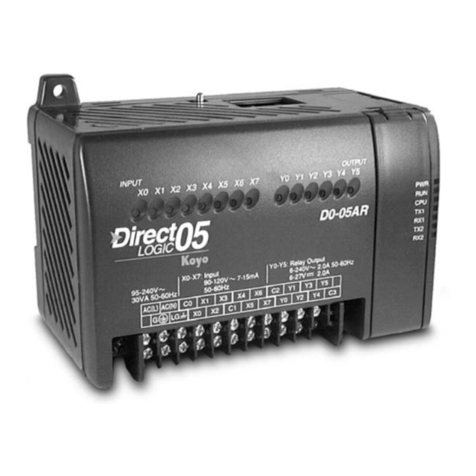
Automationdirect.com DL06 User manual

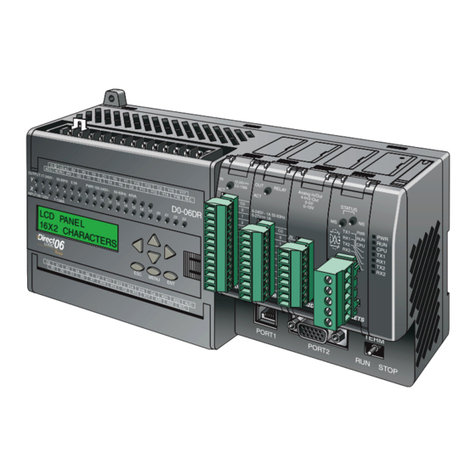
DL06 Micro PLC User Manual
Volume 1 of 2
Manual Number: D0-06USER-M

~ WARNING ~
Thank you for purchasing automation equipment from Automationdirect.com®, doing business as,
AutomationDirect. We want your new automation equipment to operate safely. Anyone who installs or
uses this equipment should read this publication (and any other relevant publications) before installing or
operating the equipment.
To minimize the risk of potential safety problems, you should follow all applicable local and national
codes that regulate the installation and operation of your equipment. These codes vary from area to area
and usually change with time. It is your responsibility to determine which codes should be followed, and
to verify that the equipment, installation, and operation is in compliance with the latest revision of these
codes.
At a minimum, you should follow all applicable sections of the National Fire Code, National Electrical
Code, and the codes of the National Electrical Manufacturer’s Association (NEMA). There may be local
regulatory or government offices that can also help determine which codes and standards are necessary for
safe installation and operation.
Equipment damage or serious injury to personnel can result from the failure to follow all applicable
codes and standards. We do not guarantee the products described in this publication are suitable for
your particular application, nor do we assume any responsibility for your product design, installation, or
operation.
Our products are not fault-tolerant and are not designed, manufactured or intended for use or resale as
on-line control equipment in hazardous environments requiring fail-safe performance, such as in the
operation of nuclear facilities, aircraft navigation or communication systems, air traffic control, direct life
support machines, or weapons systems, in which the failure of the product could lead directly to death,
personal injury, or severe physical or environmental damage (“High Risk Activities”). AutomationDirect
specifically disclaims any expressed or implied warranty of fitness for High Risk Activities.
For additional warranty and safety information, see the Terms and Conditions section of our catalog.
If you have any questions concerning the installation or operation of this equipment, or if you need
additional information, please call us at 770-844-4200.
This publication is based on information that was available at the time it was printed. At
AutomationDirect we constantly strive to improve our products and services, so we reserve the right to
make changes to the products and/or publications at any time without notice and without any obligation.
This publication may also discuss features that may not be available in certain revisions of the product.
Trademarks
This publication may contain references to products produced and/or offered by other companies. The
product and company names may be trademarked and are the sole property of their respective owners.
AutomationDirect disclaims any proprietary interest in the marks and names of others.
Copyright 2016, Automationdirect.com Incorporated
All Rights Reserved
No part of this manual shall be copied, reproduced, or transmitted in any way without the prior, written
consent of Automationdirect.com Incorporated. AutomationDirect retains the exclusive rights to all
information included in this document.

~AVERTISSEMENT ~
Nous vous remercions d’avoir acheté l’équipement d’automatisation de Automationdirect.comMC, en faisant des
affaires comme, AutomationDirect. Nous tenons à ce que votre nouvel équipement d’automatisation fonctionne en
toute sécurité. Toute personne qui installe ou utilise cet équipement doit lire la présente publication (et toutes les
autres publications pertinentes) avant de l’installer ou de l’utiliser.
Afin de réduire au minimum le risque d’éventuels problèmes de sécurité, vous devez respecter tous les codes locaux
et nationaux applicables régissant l’installation et le fonctionnement de votre équipement. Ces codes diffèrent d’une
région à l’autre et, habituellement, évoluent au fil du temps. Il vous incombe de déterminer les codes à respecter et
de vous assurer que l’équipement, l’installation et le fonctionnement sont conformes aux exigences de la version la
plus récente de ces codes.
Vous devez, à tout le moins, respecter toutes les sections applicables du Code national de prévention des incendies,
du Code national de l’électricité et des codes de la National Electrical Manufacturer’s Association (NEMA). Des
organismes de réglementation ou des services gouvernementaux locaux peuvent également vous aider à déterminer
les codes ainsi que les normes à respecter pour assurer une installation et un fonctionnement sûrs.
L’omission de respecter la totalité des codes et des normes applicables peut entraîner des dommages à l’équipement
ou causer de graves blessures au personnel. Nous ne garantissons pas que les produits décrits dans cette publication
conviennent à votre application particulière et nous n’assumons aucune responsabilité à l’égard de la conception, de
l’installation ou du fonctionnement de votre produit.
Nos produits ne sont pas insensibles aux défaillances et ne sont ni conçus ni fabriqués pour l’utilisation ou la revente
en tant qu’équipement de commande en ligne dans des environnements dangereux nécessitant une sécurité absolue,
par exemple, l’exploitation d’installations nucléaires, les systèmes de navigation aérienne ou de communication, le
contrôle de la circulation aérienne, les équipements de survie ou les systèmes d’armes, pour lesquels la défaillance du
produit peut provoquer la mort, des blessures corporelles ou de graves dommages matériels ou environnementaux
(«activités à risque élevé»). La société AutomationDirect nie toute garantie expresse ou implicite d’aptitude à
l’emploi en ce qui a trait aux activités à risque élevé.
Pour des renseignements additionnels touchant la garantie et la sécurité, veuillez consulter la section Modalités et
conditions de notre documentation. Si vous avez des questions au sujet de l’installation ou du fonctionnement de cet
équipement, ou encore si vous avez besoin de renseignements supplémentaires, n’hésitez pas à nous téléphoner au
770-844-4200.
Cette publication s’appuie sur l’information qui était disponible au moment de l’impression. À la société
AutomationDirect, nous nous efforçons constamment d’améliorer nos produits et services. C’est pourquoi nous
nous réservons le droit d’apporter des modifications aux produits ou aux publications en tout temps, sans préavis ni
quelque obligation que ce soit. La présente publication peut aussi porter sur des caractéristiques susceptibles de ne
pas être offertes dans certaines versions révisées du produit.
Marques de commerce
La présente publication peut contenir des références à des produits fabriqués ou offerts par d’autres entreprises. Les
désignations des produits et des entreprises peuvent être des marques de commerce et appartiennent exclusivement à
leurs propriétaires respectifs. AutomationDirect nie tout intérêt dans les autres marques et désignations.
Copyright 2016, Automationdirect.com Incorporated
Tous droits réservés
Nulle partie de ce manuel ne doit être copiée, reproduite ou transmise de quelque façon que ce soit sans le
consentement préalable écrit de la société Automationdirect.com Incorporated. AutomationDirect conserve les
droits exclusifs à l’égard de tous les renseignements contenus dans le présent document.
DL06 Micro PLc USER MANUAL
Please include the Manual Number and the Manual Issue, both shown below,
when communicating with Technical Support regarding this publication.
Manual Number: D0-06USER-M
Issue: 3rd Edition, Rev. E
Issue Date: 8/18
Publication History
Issue Date Description of Changes
First Edition 7/02 Original
Rev. A 10/02 Updated drawing images and made minor corrections.
Rev. B 6/03 Added new PLC and made numerous corrections.
2nd Edition 3/04 Added two appendices, removed discrete module data and made numerous
corrections.
3rd Edition 3/07
Corrected all tables, many corrections to Chapters 2, 3, 4, 5, 6, and 7; Chapter 3
(HSIO) was moved to the Appendices and Chapter 4 was divided into Chapters 3 &
4; added DS5 Intelligent Boxes to Chapter 5; added Ramp/Soak example to Chapter
8; Numbering Systems and Serial Communications were added to Appendices; many
minor corrections were made throughout manual.
Rev. A 5/07 Minor corrections and updates.
Rev. B 6/11 Updated Chapter 5 with current DirectSOFT dialog views, corrected number of
registers needed to use the print message instruction, removed fuses and corrected
I/O wiring drawings, and other minor corrections and updates.
Rev. C 2/13 Added H0-CTRIO2 references.
Minor corrections and updates.
Added transient suppression for inductive loads.
Rev. D 6/16 Corrections and updates.
Rev. E 8/18 Corrections, updates, removed mention of the DA-EU-M from Appendix J.

DL06 Micro PLC User Manual 3rd Edition, Rev.E
Notes

Table of ConTenTs
Chapter 1: Getting Started
Introduction...............................................................................................................1–2
The Purpose of this Manual......................................................................................1–2
Supplemental Manuals.............................................................................................1–2
Technical Support ....................................................................................................1–2
Conventions Used......................................................................................................1–3
Key Topics for Each Chapter.....................................................................................1–3
DL06 Micro PLC Overview.........................................................................................1–4
The DL06 PLC Features ............................................................................................1–4
DirectSOFT Programming for Windows™ ................................................................1–4
Handheld Programmer.............................................................................................1–5
I/O Quick Selection Guide.........................................................................................1–5
Quick Start .................................................................................................................1–6
Steps to Designing a Successful System.................................................................1–10
Questions and Answers about DL06 Micro PLCs....................................................1–12
Chapter 2: Installation, Wiring, and Specifications
Safety Guidelines.......................................................................................................2–2
Plan for Safety ..........................................................................................................2–2
Three Levels of Protection ........................................................................................2–3
Emergency Stops......................................................................................................2–3
Emergency Power Disconnect ..................................................................................2–4
Orderly System Shutdown........................................................................................2–4
Class 1, Division 2 Approval .....................................................................................2–4
Orientation to DL06 Front Panel ..............................................................................2–5
Terminal Block Removal ...........................................................................................2–6
Mounting Guidelines.................................................................................................2–7

DL06 Micro PLC User Manual, 3rd Edition, Rev. E
ii
Table of Contents
Unit Dimensions.......................................................................................................2–7
Enclosures ................................................................................................................2–7
Panel Layout & Clearances.......................................................................................2–8
Using Mounting Rails ...............................................................................................2–9
Environmental Specifications..................................................................................2–10
Agency Approvals...................................................................................................2–10
Marine Use.............................................................................................................2–10
Wiring Guidelines ....................................................................................................2–11
External Power Source............................................................................................2–12
Planning the Wiring Routes....................................................................................2–12
Fuse Protection for Input and Output Circuits........................................................2–13
I/O Point Numbering .............................................................................................2–13
System Wiring Strategies ........................................................................................2–14
PLC Isolation Boundaries ........................................................................................2–14
Connecting Operator Interface Devices..................................................................2–15
Connecting Programming Devices .........................................................................2–15
Sinking / Sourcing Concepts ..................................................................................2–16
I/O “Common” Terminal Concepts........................................................................2–17
Connecting DC I/O to “Solid State” Field Devices..................................................2–18
Solid State Input Sensors........................................................................................2–18
Solid State Output Loads........................................................................................2–18
Relay Output Wiring Methods................................................................................2–20
Relay Outputs-Transient Suppression For Inductive Loads in a Control System.......2–21
Prolonging Relay Contact Life ................................................................................2–26
DC Input Wiring Methods......................................................................................2–27
DC Output Wiring Methods...................................................................................2–28
High-Speed I/O Wiring Methods............................................................................2–29
Wiring Diagrams and Specifications.......................................................................2–30
D0–06AA I/O Wiring Diagram................................................................................2–30
D0–06AR I/O Wiring Diagram................................................................................2–32
D0–06DA I/O Wiring Diagram ...............................................................................2–34
D0–06DD1 I/O Wiring Diagram.............................................................................2–36
D0–06DD2 I/O Wiring Diagram.............................................................................2–38
D0–06DR I/O Wiring Diagram................................................................................2–40
D0–06DD1–D I/O Wiring Diagram.........................................................................2–42
D0–06DD2–D I/O Wiring Diagram.........................................................................2–44
D0–06DR–D I/O Wiring Diagram ...........................................................................2–46

DL06 Micro PLC User Manual, 3rd Edition, Rev. E iii
Table of Contents
Glossary of Specification Terms ..............................................................................2–48
Chapter 3: CPU Specifications and Operation
Overview3–2
DL06 CPU Features ..................................................................................................3–2
CPU Specifications.....................................................................................................3–3
CPU Hardware Setup.................................................................................................3–4
Communication Port Pinout Diagrams .....................................................................3–4
Connecting the Programming Devices.....................................................................3–5
CPU Setup Information ............................................................................................3–5
Status Indicators.......................................................................................................3–6
Mode Switch Functions............................................................................................3–6
Changing Modes in the DL06 PLC ...........................................................................3–7
Mode of Operation at Power-up ..............................................................................3–7
Using Battery Backup ................................................................................................3–8
Battery Backup .........................................................................................................3–8
Auxiliary Functions ...................................................................................................3–9
Clearing an Existing Program ...................................................................................3–9
Initializing System Memory ......................................................................................3–9
Setting Retentive Memory Ranges..........................................................................3–10
Using a Password ...................................................................................................3–11
CPU Operation.........................................................................................................3–12
CPU Operating System...........................................................................................3–12
Program Mode.......................................................................................................3–13
Run Mode ..............................................................................................................3–13
Read Inputs............................................................................................................3–14
Service Peripherals and Force I/O ...........................................................................3–14
CPU Bus Communication .......................................................................................3–15
Update Clock, Special Relays and Special Registers.................................................3–15
Solve Application Program .....................................................................................3–16
Solve PID Loop Equations.......................................................................................3–16
Write Outputs ........................................................................................................3–16
Write Outputs to Specialty I/O ...............................................................................3–16
Diagnostics.............................................................................................................3–17
I/O Response Time ..................................................................................................3–17
Is Timing Important for Your Application?..............................................................3–17

DL06 Micro PLC User Manual, 3rd Edition, Rev. E
iv
Table of Contents
Normal Minimum I/O Response.............................................................................3–18
Normal Maximum I/O Response ............................................................................3–18
Improving Response Time ......................................................................................3–19
CPU Scan Time Considerations...............................................................................3–20
Reading Inputs .......................................................................................................3–20
Writing Outputs .....................................................................................................3–20
Service Peripherals..................................................................................................3–21
CPU Bus Communication .......................................................................................3–21
Update Clock/Calendar, Special Relays, Special Registers .......................................3–21
Application Program Execution ..............................................................................3–22
PLC Numbering Systems........................................................................................3–23
PLC Resources ........................................................................................................3–23
V–Memory .............................................................................................................3–24
Binary-Coded Decimal Numbers ............................................................................3–24
Hexadecimal Numbers ...........................................................................................3–24
Memory Map ...........................................................................................................3–25
Octal Numbering System.......................................................................................3–25
Discrete and Word Locations..................................................................................3–25
V-memory Locations for Discrete Memory Areas ....................................................3–25
Input Points (X Data Type).....................................................................................3–26
Output Points (Y Data Type) ..................................................................................3–26
Control Relays (C Data Type) .................................................................................3–26
Timers and Timer Status Bits (T Data Type)............................................................3–26
Timer Current Values (V Data Type) .......................................................................3–27
Counters and Counter Status Bits (CT Data type)...................................................3–27
Counter Current Values (V Data Type) ...................................................................3–27
Word Memory (V Data Type).................................................................................3–28
Stages (S Data type)...............................................................................................3–28
Special Relays (SP Data Type).................................................................................3–28
DL06 System V-memory..........................................................................................3–29
System Parameters and Default Data Locations (V Data Type) ...............................3–29
DL06 Aliases.............................................................................................................3–31
DL06 Memory Map..................................................................................................3–32
X Input/Y Output Bit Map ......................................................................................3–33
Stage Control/Status Bit Map.................................................................................3–34
Control Relay Bit Map .............................................................................................3–36

DL06 Micro PLC User Manual, 3rd Edition, Rev. E v
Table of Contents
Timer Status Bit Map...............................................................................................3–38
Counter Status Bit Map...........................................................................................3–38
GX and GY I/O Bit Map ..........................................................................................3–39
Chapter 4: System Design and Configuration
DL06 System Design Strategies ................................................................................4–2
I/O System Configurations .......................................................................................4–2
Networking Configurations ......................................................................................4–2
Module Placement.....................................................................................................4–3
Slot Numbering........................................................................................................4–3
Automatic I/O Configuration....................................................................................4–4
Manual I/O Configuration ........................................................................................4–4
Power Budgeting.......................................................................................................4–5
Power supplied .......................................................................................................4–5
Power required by base unit ...................................................................................4–5
Power required by option cards ..............................................................................4–5
Configuring the DL06’s Comm Ports........................................................................4–7
DL06 Port Specifications...........................................................................................4–7
DL06 Port Pinouts ....................................................................................................4–7
Choosing a Network Specification............................................................................4–8
RS-232 Network.......................................................................................................4–8
RS-422 Network.......................................................................................................4–8
RS-485 Network.......................................................................................................4–8
Connecting to MODBUS and DirectNET Networks..................................................4–9
MODBUS Port Configuration....................................................................................4–9
DirectNET Port Configuration.................................................................................4–10
Non–Sequence Protocol (ASCII In/Out and PRINT)...............................................4–11
Non-Sequence Port Configuration..........................................................................4–11
Network Slave Operation........................................................................................4–12
MODBUS Function Codes Supported.....................................................................4–12
Determining the MODBUS Address........................................................................4–12
If Your Host Software Requires the Data Type and Address ....................................4–13
Example 1: V2100..................................................................................................4–14
Example 2: Y20 ......................................................................................................4–14
Example 3: T10 Current Value................................................................................4–14

DL06 Micro PLC User Manual, 3rd Edition, Rev. E
vi
Table of Contents
Example 4: C54......................................................................................................4–14
If Your MODBUS Host Software Requires an Address ONLY ...................................4–15
Example 1: V2100 584/984 Mode .........................................................................4–16
Example 2: Y20 584/984 Mode .............................................................................4–16
Example 3: T10 Current Value 484 Mode ..............................................................4–17
Example 4: C54 584/984 Mode.............................................................................4–17
Network Master Operation.....................................................................................4–17
Step 1: Identify Master Port # and Slave #..............................................................4–18
Step 2: Load Number of Bytes to Transfer..............................................................4–18
Step 3: Specify Master Memory Area......................................................................4–19
Step 4: Specify Slave Memory Area ........................................................................4–20
Communications from a Ladder Program...............................................................4–21
Multiple Read and Write Interlocks.........................................................................4–21
Network Master Operation (using MRX and MWX Instructions) .........................4–22
MODBUS Function Codes Supported.....................................................................4–22
MODBUS Read from Network(MRX) ......................................................................4–23
MRX Slave Memory Address...................................................................................4–24
MRX Master Memory Addresses.............................................................................4–24
MRX Number of Elements......................................................................................4–24
MRX Exception Response Buffer .............................................................................4–24
MODBUS Write to Network (MWX) .......................................................................4–25
MWX Slave Memory Address .................................................................................4–26
MWX Master Memory Addresses............................................................................4–26
MWX Number of Elements.....................................................................................4–26
MWX Exception Response Buffer............................................................................4–26
MRX/MWX Example in DirectSOFT ........................................................................4–27
Multiple Read and Write Interlocks.........................................................................4–27
Chapter 5: Standard RLL Instructions
Introduction...............................................................................................................5–2
Using Boolean Instructions .......................................................................................5–5
END Statement ........................................................................................................5–5
Simple Rungs ...........................................................................................................5–5
Normally Closed Contact .........................................................................................5–6
Contacts in Series.....................................................................................................5–6
Midline Outputs.......................................................................................................5–6

DL06 Micro PLC User Manual, 3rd Edition, Rev. E vii
Table of Contents
Parallel Elements.......................................................................................................5–7
Joining Series Branches in Parallel.............................................................................5–7
Joining Parallel Branches in Series.............................................................................5–7
Combination Networks ............................................................................................5–7
Comparative Boolean...............................................................................................5–8
Boolean Stack...........................................................................................................5–8
Immediate Boolean ..................................................................................................5–9
Boolean Instructions ...............................................................................................5–10
Comparative Boolean ..............................................................................................5–26
Immediate Instructions ...........................................................................................5–32
Timer, Counter and Shift Register Instructions......................................................5–39
Using Timers ..........................................................................................................5–39
Timer Example Using Discrete Status Bits ...............................................................5–41
Timer Example Using Comparative Contacts..........................................................5–41
Accumulating Timer Example using Discrete Status Bits .........................................5–43
Accumulator Timer Example Using Comparative Contacts .....................................5–43
Using Counters.......................................................................................................5–44
Counter Example Using Discrete Status Bits ...........................................................5–46
Counter Example Using Comparative Contacts ......................................................5–46
Stage Counter Example Using Discrete Status Bits..................................................5–48
Stage Counter Example Using Comparative Contacts ............................................5–48
Up / Down Counter Example Using Discrete Status Bits.........................................5–50
Up / Down Counter Example Using Comparative Contacts....................................5–50
Accumulator/Stack Load and Output Data Instructions ........................................5–52
Using the Accumulator...........................................................................................5–52
Copying Data to the Accumulator..........................................................................5–52
Changing the Accumulator Data............................................................................5–53
Using the Accumulator Stack..................................................................................5–54
Using Pointers ........................................................................................................5–55
Logical Instructions (Accumulator).........................................................................5–69
Math Instructions ....................................................................................................5–86
Transcendental Functions......................................................................................5–118
Bit Operation Instructions.....................................................................................5–120
Number Conversion Instructions (Accumulator)..................................................5–127
Shuffle Digits Block Diagram ................................................................................5–139

DL06 Micro PLC User Manual, 3rd Edition, Rev. E
viii
Table of Contents
Table Instructions ..................................................................................................5–141
Copy Data From a Data Label Area to V-memory.................................................5–143
Clock/Calendar Instructions..................................................................................5–171
CPU Control Instructions.......................................................................................5–173
Program Control Instructions ...............................................................................5–175
Interrupt Instructions ............................................................................................5–183
Message Instructions.............................................................................................5–186
Move Block Instruction (MOVBLK) .......................................................................5–189
Copy Data From a Data Label Area to V-memory.................................................5–189
Intelligent I/O Instructions....................................................................................5–194
Read from Intelligent Module (RD).......................................................................5–194
Write to Intelligent Module (WT) .........................................................................5–195
Network Instructions.............................................................................................5–196
Direct Text Entry ..................................................................................................5–200
Embedding date and/or time variables.................................................................5–201
Embedding V-memory data .................................................................................5–201
Data Format Suffixes for Embedded V-memory Data............................................5–202
Text Entry from V-memory...................................................................................5–203
MODBUS RTU Instructions ...................................................................................5–204
MRX Slave Address Ranges...................................................................................5–205
MWX Slave Address Ranges..................................................................................5–208
MWX Master Memory Address Ranges.................................................................5–208
MWX Number of Elements ................................................................................5–208
MWX Exception Response Buffer..........................................................................5–208
ASCII Instructions ..................................................................................................5–210
Reading ASCII Input Strings..................................................................................5–210
Writing ASCII Output Strings................................................................................5–210
Managing the ASCII Strings .................................................................................5–211
Intelligent Box (IBox) Instructions........................................................................5–230
Chapter 6: Drum Instruction Programming
Introduction...............................................................................................................6–2

DL06 Micro PLC User Manual, 3rd Edition, Rev. E ix
Table of Contents
Purpose....................................................................................................................6–2
Drum Terminology...................................................................................................6–2
Drum Chart Representation......................................................................................6–3
Output Sequences....................................................................................................6–3
Step Transitions.........................................................................................................6–4
Drum Instruction Types............................................................................................6–4
Timer-Only Transitions .............................................................................................6–4
Timer and Event Transitions .....................................................................................6–5
Event-Only Transitions..............................................................................................6–6
Counter Assignments ...............................................................................................6–6
Last Step Completion...............................................................................................6–7
Overview of Drum Operation ...................................................................................6–8
Drum Instruction Block Diagram ..............................................................................6–8
Powerup State of Drum Registers .............................................................................6–9
Drum Control Techniques.......................................................................................6–10
Drum Control Inputs..............................................................................................6–10
Self-Resetting Drum................................................................................................6–11
Initializing Drum Outputs.......................................................................................6–11
Using Complex Event Step Transitions ...................................................................6–11
Drum Instruction .....................................................................................................6–12
Timed Drum with Discrete Outputs (DRUM)..........................................................6–12
Event Drum (EDRUM) ............................................................................................6–14
Handheld Programmer Drum Mnemonics..............................................................6–16
Masked Event Drum with Discrete Outputs (MDRMD)...........................................6–19
Masked Event Drum with Word Output (MDRMW) ...............................................6–21
VoLuMe Two:
TabLe of conTenTs

DL06 Micro PLC User Manual, 3rd Edition, Rev. E
x
Table of Contents
Chapter 7: RLLPLUS Stage Programming
Introduction to Stage Programming ........................................................................7–2
Overcoming “Stage Fright”......................................................................................7–2
Learning to Draw State Transition Diagrams...........................................................7–3
Introduction to Process States ..................................................................................7–3
The Need for State Diagrams ...................................................................................7–3
A 2–State Process .....................................................................................................7–3
RLL Equivalent..........................................................................................................7–4
Stage Equivalent.......................................................................................................7–4
Let’s Compare..........................................................................................................7–5
Initial Stages.............................................................................................................7–5
What Stage Bits Do ..................................................................................................7–6
Stage Instruction Characteristics...............................................................................7–6
Using the Stage Jump Instruction for State Transitions ..........................................7–7
Stage Jump, Set, and Reset Instructions....................................................................7–7
Stage Program Example: Toggle On/Off Lamp Controller......................................7–8
A 4–State Process .....................................................................................................7–8
Four Steps to Writing a Stage Program ...................................................................7–9
1. Write a Word Description of the application. .......................................................7–9
2. Draw the Block Diagram. .....................................................................................7–9
3. Draw the State Transition Diagram. .....................................................................7–9
4. Write the Stage Program......................................................................................7–9
Stage Program Example: A Garage Door Opener..................................................7–10
Garage Door Opener Example ...............................................................................7–10
Draw the Block Diagram ........................................................................................7–10
Draw the State Diagram.........................................................................................7–11
Add Safety Light Feature ........................................................................................7–12
Modify the Block Diagram and State Diagram .......................................................7–12
Using a Timer Inside a Stage ..................................................................................7–13
Add Emergency Stop Feature .................................................................................7–14
Exclusive Transitions...............................................................................................7–14
Stage Program Design Considerations...................................................................7–15
Stage Program Organization ..................................................................................7–15
How Instructions Work Inside Stages......................................................................7–16
Using a Stage as a Supervisory Process...................................................................7–17

DL06 Micro PLC User Manual, 3rd Edition, Rev. E xi
Table of Contents
Stage Counter........................................................................................................7–17
Power Flow Transition Technique...........................................................................7–18
Stage View in DirectSOFT.......................................................................................7–18
Parallel Processing Concepts...................................................................................7–19
Parallel Processes....................................................................................................7–19
Converging Processes.............................................................................................7–19
Convergence Stages (CV).......................................................................................7–19
Convergence Jump (CVJMP)...................................................................................7–20
Convergence Stage Guidelines...............................................................................7–20
RLLPLUS (Stage) Instructions ....................................................................................7–21
Stage (SG)..............................................................................................................7–21
Initial Stage (ISG) ...................................................................................................7–22
Jump (JMP).............................................................................................................7–22
Not Jump (NJMP)...................................................................................................7–22
Converge Stage (CV) and Converge Jump (CVJMP) ...............................................7–23
Block Call (BCALL)..................................................................................................7–25
Block (BLK).............................................................................................................7–25
Block End (BEND)...................................................................................................7–25
Questions and Answers about Stage Programming ..............................................7–27
Chapter 8: PID Loop Operation
DL06 PID Control.......................................................................................................8–2
DL06 PID Control Features.......................................................................................8–2
Introduction to PID Control......................................................................................8–4
What is PID Control?................................................................................................8–4
Introducing DL06 PID Control ..................................................................................8–6
Process Control Definitions.......................................................................................8–8
PID Loop Operation...................................................................................................8–9
Position Form of the PID Equation............................................................................8–9
Reset Windup Protection........................................................................................8–10
Freeze Bias .............................................................................................................8–11
Adjusting the Bias...................................................................................................8–11
Step Bias Proportional to Step Change in SP ..........................................................8–12
Eliminating Proportional, Integral or Derivative Action ...........................................8–12
Velocity Form of the PID Equation..........................................................................8–12

DL06 Micro PLC User Manual, 3rd Edition, Rev. E
xii
Table of Contents
Bumpless Transfer ..................................................................................................8–13
Loop Alarms...........................................................................................................8–13
Loop Operating Modes ..........................................................................................8–14
Special Loop Calculations.......................................................................................8–14
Ten Steps to Successful Process Control.................................................................8–16
PID Loop Setup........................................................................................................8–18
Some Things to Do and Know Before Starting .......................................................8–18
PID Error Flags........................................................................................................8–18
Establishing the Loop Table Size and Location .......................................................8–18
Loop Table Word Definitions..................................................................................8–20
PID Mode Setting 1 Bit Descriptions (Addr + 00) ...................................................8–21
PID Mode Setting 2 Bit Descriptions (Addr + 01) ...................................................8–22
Mode/Alarm Monitoring Word (Addr + 06) ...........................................................8–23
Ramp/Soak Table Flags (Addr + 33) .......................................................................8–23
Ramp/Soak Table Location (Addr + 34)..................................................................8–24
Ramp/Soak Table Programming Error Flags (Addr + 35).........................................8–24
Configure the PID Loop..........................................................................................8–25
PID Loop Tuning......................................................................................................8–40
Open-Loop Test .....................................................................................................8–40
Manual Tuning Procedure......................................................................................8–41
Alternative Manual Tuning Procedures by Others...................................................8–44
Tuning PID Controllers...........................................................................................8–44
Auto Tuning Procedure ..........................................................................................8–45
Use DirectSOFT 5 Data View with PID View ...........................................................8–49
Open a New Data View Window............................................................................8–49
Open PID View.......................................................................................................8–50
Using the Special PID Features ...............................................................................8–53
How to Change Loop Modes .................................................................................8–53
Operator Panel Control of PID Modes....................................................................8–54
PLC Modes Effect on Loop Modes..........................................................................8–54
Loop Mode Override..............................................................................................8–54
PV Analog Filter......................................................................................................8–55
Creating an Analog Filter in Ladder Logic...............................................................8–56
Use the DirectSOFT Filter Intelligent Box Instructions ............................................. 8-57
FilterB Example....................................................................................................... 8-57
Ramp/Soak Generator.............................................................................................8–58

DL06 Micro PLC User Manual, 3rd Edition, Rev. E xiii
Table of Contents
Introduction ...........................................................................................................8–58
Ramp/Soak Table ...................................................................................................8–59
Ramp/Soak Table Flags...........................................................................................8–61
Ramp/Soak Generator Enable.................................................................................8–61
Ramp/Soak Controls...............................................................................................8–61
Ramp/Soak Profile Monitoring................................................................................8–62
Ramp/Soak Programming Errors.............................................................................8–62
Testing Your Ramp/Soak Profile..............................................................................8–62
DirectSOFT Ramp/Soak Example ............................................................................. 8-63
Setup the Profile in PID Setup ................................................................................ 8-63
Program the Ramp/Soak Control in Relay Ladder................................................... 8-63
Test the Profile ....................................................................................................... 8-64
Cascade Control.......................................................................................................8–65
Introduction ...........................................................................................................8–65
Cascaded Loops in the DL06 CPU ..........................................................................8–66
Tuning Cascaded Loops .........................................................................................8–67
Time-Proportioning Control....................................................................................8–68
On/Off Control Program Example..........................................................................8–69
Feedforward Control ...............................................................................................8–70
Feedforward Example.............................................................................................8–71
PID Example Program .............................................................................................8–72
Program Setup for the PID Loop ............................................................................8–72
Troubleshooting Tips...............................................................................................8–75
Glossary of PID Loop Terminology .........................................................................8–77
Bibliography ...........................................................................................................8–79
Chapter 9: Maintenance and Troubleshooting
Hardware System Maintenance ................................................................................9–2
Standard Maintenance .............................................................................................9–2
Diagnostics.................................................................................................................9–2
Diagnostics...............................................................................................................9–2
Fatal Errors ...............................................................................................................9–2
Non-fatal Errors........................................................................................................9–2
V-memory Error Code Locations...............................................................................9–3
Special Relays (SP) Corresponding to Error Codes ....................................................9–3

DL06 Micro PLC User Manual, 3rd Edition, Rev. E
xiv
Table of Contents
DL06 Micro PLC Error Codes....................................................................................9–4
Program Error Codes................................................................................................9–5
CPU Indicators ...........................................................................................................9–6
PWR Indicator ..........................................................................................................9–6
RUN Indicator ..........................................................................................................9–7
CPU Indicator...........................................................................................................9–7
Communications Problems .......................................................................................9–7
I/O Point Troubleshooting........................................................................................9–8
Possible Causes ........................................................................................................9–8
Some Quick Steps ....................................................................................................9–8
Handheld Programmer Keystrokes Used to Test an Output Point.............................9–9
Noise Troubleshooting............................................................................................9–10
Electrical Noise Problems........................................................................................9–10
Reducing Electrical Noise........................................................................................9–10
Machine Startup and Program Troubleshooting ...................................................9–11
Syntax Check .........................................................................................................9–11
Special Instructions.................................................................................................9–12
Duplicate Reference Check.....................................................................................9–13
Run Time Edits .......................................................................................................9–14
Run Time Edit Example ..........................................................................................9–15
Forcing I/O Points ..................................................................................................9–16
Regular Forcing with Direct Access.........................................................................9–18
Bit Override Forcing ...............................................................................................9–19
Bit Override Indicators............................................................................................9–19
Reset the PLC to Factory Defaults...........................................................................9–20
Chapter 10: LCD Display Panel
Introduction to the DL06 LCD Display Panel .........................................................10–2
Keypad .. 10–2
Snap-in installation..................................................................................................10–3
Display Priority ........................................................................................................10–4
Menu Navigation.....................................................................................................10–5
Confirm PLC Type, Firmware Revision Level, Memory Usage, Etc. .......................10–6
Examining Option Slot Contents ............................................................................10–8

DL06 Micro PLC User Manual, 3rd Edition, Rev. E xv
Table of Contents
Menu 2, M2:SYSTEM CFG. ....................................................................................10–8
Monitoring and Changing Data Values................................................................10–10
Menu 3, M3:MONITOR ......................................................................................10–10
Data Monitor .......................................................................................................10–10
V-memory values..................................................................................................10–10
Pointer values.......................................................................................................10–12
Bit Monitor ............................................................................................................10–13
Bit status ..............................................................................................................10–13
Changing Date and Time ......................................................................................10–14
Menu 4, M4 : CALENDAR R/W.............................................................................10–14
Setting Password and Locking..............................................................................10–17
Menu 5, M5 : PASSWORD R/W............................................................................10–17
Reviewing Error History.........................................................................................10–20
Menu 6, M6 : ERR HISTORY .................................................................................10–20
Toggle Light and Beeper, Test Keys .....................................................................10–21
Menu 7, M7 : LCD TEST&SET ..............................................................................10–21
PLC Memory Information for the LCD Display Panel ..........................................10–22
Data Format Suffixes for Embedded V-memory Data............................................10–22
Reserved memory registers for the LCD Display Panel..........................................10–23
V7742 bit definitions............................................................................................10–24
Changing the Default Screen................................................................................10–25
Example program for setting the default screen message.....................................10–25
DL06 LCD Display Panel Instruction (LCD)...........................................................10–26
Source of message ...............................................................................................10–26
ASCII Character Codes .........................................................................................10–27
Example program: alarm with embedded date/time stamp .................................10–28
Example program: alarm with embedded V-memory data ...................................10–29
Example program: alarm text from V-memory with embedded V-memory data ..10–30
Appendix A: Auxiliary Functions
Introduction...............................................................................................................A–2
Purpose of Auxiliary Functions..................................................................................A–2
Accessing AUX Functions via DirectSOFT..................................................................A–3
Accessing AUX Functions via the Handheld Programmer..........................................A–3
Other manuals for DL06
2
Table of contents
Other Automationdirect.com Controllers manuals

Automationdirect.com
Automationdirect.com IronHorse GSD Series User manual

Automationdirect.com
Automationdirect.com prosense PPC5 Series User manual

Automationdirect.com
Automationdirect.com T1H Series Instructions for use

Automationdirect.com
Automationdirect.com Stellar SR44 User manual

Automationdirect.com
Automationdirect.com DirectLOGIC DL205 Series User manual

Automationdirect.com
Automationdirect.com DL06 User manual

Automationdirect.com
Automationdirect.com GS1-10P2 User manual

Automationdirect.com
Automationdirect.com DL05 User manual

Automationdirect.com
Automationdirect.com D4-454 PLC User manual

Automationdirect.com
Automationdirect.com DL05 User manual