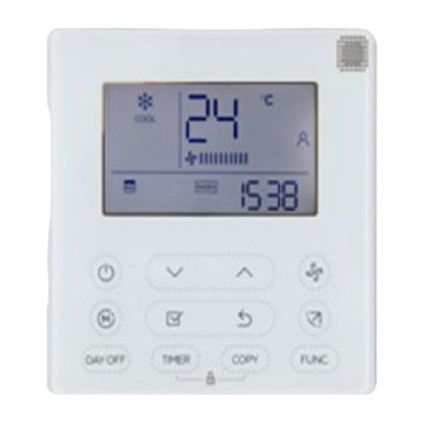
Mars Comfort-Aire Century KJR-120G1/TFBG-E-01 Installation instructions

Wired Controller IOM - VMHxxDU
517.787.2100 • www.marsdelivers.com
WIRED CONTROLLER
INSTALLATION AND OWNER’S
MANUAL
Model
KJR-120G1/TFBG-E-01
KJR-120G2/TFBG-E-03

Wired Controller IOM - VMHxxDU
●This manual gives detailed description of the precautions that should be
brought to your attention during operation.
●To ensure the correct service of the wired controller, read this manual
carefully before using the unit.
●Keep this manual after reading for future reference.

Wired Controller IOM - VMHxxDU
1. SAFETY PRECAUTION................................................................................................... 1
2. INSTALLATION ACCESSORY........................................................................................ 2
3. INSTALLATION METHOD..............................................................................................4
4. APPENDIX INSTALL THE WIRED
D
CONTROLLER KIT...............................................11
5. SPECIFICATION..............................................................................................................17
6.WIRED CONTROLLER FEATURES AND FUNCTIONS..........................................18
7.WIRED CONTROLLER DISPLAY.................................................................................19
8.WIRED CONTROLLER BUTTONS..............................................................................20
9. PREPARATORY OPERATION.......................................................................................21
10. OPERATION..................................................................................................................22
11.TIMER FUNCTIONS.....................................................................................................28
12.WEEKLY TIMER.............................................................................................................31
13. SET EXTERNAL STATIC PRESSURE.........................................................................38
14. FAULT ALARM HANDL
L
ING.........................................................................................39
15.TECHNICAL INDICATION AND REQUIREMENT .................................................39

Wired Controller IOM - VMHxxDU
1
1
Read the safety precautions carefully before installing the unit.
Stated below are important safety issues that must be obeyed.
Means improper handling may lead to personal death or severe injury.
Means improper handling may lead to personal injury or property loss.
WARNING
CAUTION
P
P
l
l
e
e
a
a
s
s
e
e
e
e
n
n
t
t
r
r
u
u
s
s
t
t
t
t
h
h
e
e
d
d
i
i
s
s
t
t
r
r
i
i
b
b
u
u
t
t
o
o
r
r
o
o
r
r
p
p
r
r
o
o
f
f
e
e
s
s
s
s
i
i
o
o
n
n
a
a
l
l
s
s
t
t
o
o
i
i
n
n
s
s
t
t
a
a
l
l
l
l
t
t
h
h
e
e
u
u
n
n
i
i
t
t
.
.
I
I
n
n
s
s
t
t
a
a
l
l
l
l
a
a
t
t
i
i
o
o
n
n
b
b
y
y
o
o
t
t
h
h
e
e
r
r
p
p
e
e
r
r
s
s
o
o
n
n
s
s
m
m
a
a
y
y
l
l
e
e
a
a
d
d
t
t
o
o
i
i
m
m
p
p
e
e
r
r
f
f
e
e
c
c
t
t
i
i
n
n
s
s
t
t
a
a
l
l
l
l
a
a
t
t
i
i
o
o
n
n
,
,
e
e
l
l
e
e
c
c
t
t
r
r
i
i
c
c
s
s
h
h
o
o
c
c
k
k
o
o
r
r
f
f
i
i
r
r
e
e
.
.
A
A
d
d
h
h
e
e
r
r
e
e
t
t
o
o
t
t
h
h
i
i
s
s
i
i
n
n
s
s
t
t
a
a
l
l
l
l
a
a
t
t
i
i
o
o
n
n
m
m
a
a
n
n
u
u
a
a
l
l
.
.
I
I
m
m
p
p
r
r
o
o
p
p
e
e
r
r
i
i
n
n
s
s
t
t
a
a
l
l
l
l
a
a
t
t
i
i
o
o
n
n
m
m
a
a
y
y
l
l
e
e
a
a
d
d
t
t
o
o
e
e
l
l
e
e
c
c
t
t
r
r
i
i
c
c
s
s
h
h
o
o
c
c
k
k
o
o
r
r
f
f
i
i
r
r
e
e
.
.
R
R
e
e
-
-
i
i
n
n
s
s
t
t
a
a
l
l
l
l
a
a
t
t
i
i
o
o
n
n
m
m
u
u
s
s
t
t
b
b
e
e
p
p
e
e
r
r
f
f
o
o
r
r
m
m
e
e
d
d
b
b
y
y
p
p
r
r
o
o
f
f
e
e
s
s
s
s
i
i
o
o
n
n
a
a
l
l
s
s
.
.
WARNING
D
D
o
o
n
n
o
o
t
t
i
i
n
n
s
s
t
t
a
a
l
l
l
l
t
t
h
h
e
e
u
u
n
n
i
i
t
t
i
i
n
n
a
a
p
p
l
l
a
a
c
c
e
e
v
v
u
u
l
l
n
n
e
e
r
r
a
a
b
b
l
l
e
e
t
t
o
o
l
l
e
e
a
a
k
k
a
a
g
g
e
e
o
o
f
f
f
f
l
l
a
a
m
m
m
m
a
a
b
b
l
l
e
e
g
g
a
a
s
s
e
e
s
s
.
.
O
O
n
n
c
c
e
e
f
f
l
l
a
a
m
m
m
m
a
a
b
b
l
l
e
e
g
g
a
a
s
s
e
e
s
s
a
a
r
r
e
e
l
l
e
e
a
a
k
k
e
e
d
d
a
a
n
n
d
d
l
l
e
e
f
f
t
t
a
a
r
r
o
o
u
u
n
n
d
d
t
t
h
h
e
e
w
w
i
i
r
r
e
e
d
d
c
c
o
o
n
n
t
t
r
r
o
o
l
l
l
l
e
e
r
r
,
,
f
f
i
i
r
r
e
e
m
m
a
a
y
y
o
o
c
c
c
c
u
u
r
r
.
.
D
D
o
o
n
n
o
o
t
t
o
o
p
p
e
e
r
r
a
a
t
t
e
e
w
w
i
i
t
t
h
h
w
w
e
e
t
t
h
h
a
a
n
n
d
d
s
s
o
o
r
r
l
l
e
e
t
t
w
w
a
a
t
t
e
e
r
r
e
e
n
n
t
t
e
e
r
r
t
t
h
h
e
e
w
w
i
i
r
r
e
e
d
d
c
c
o
o
n
n
t
t
r
r
o
o
l
l
l
l
e
e
r
r
.
.
O
O
t
t
h
h
e
e
r
r
w
w
i
i
s
s
e
e
,
,
e
e
l
l
e
e
c
c
t
t
r
r
i
i
c
c
s
s
h
h
o
o
c
c
k
k
m
m
a
a
y
y
o
o
c
c
c
c
u
u
r
r
.
.
T
T
h
h
e
e
w
w
i
i
r
r
i
i
n
n
g
g
s
s
h
h
o
o
u
u
l
l
d
d
a
a
d
d
a
a
p
p
t
t
t
t
o
o
t
t
h
h
e
e
w
w
i
i
r
r
e
e
d
d
c
c
o
o
n
n
t
t
r
r
o
o
l
l
l
l
e
e
r
r
c
c
u
u
r
r
r
r
e
e
n
n
t
t
.
.
O
O
t
t
h
h
e
e
r
r
w
w
i
i
s
s
e
e
,
,
e
e
l
l
e
e
c
c
t
t
r
r
i
i
c
c
l
l
e
e
a
a
k
k
a
a
g
g
e
e
o
o
r
r
h
h
e
e
a
a
t
t
i
i
n
n
g
g
m
m
a
a
y
y
o
o
c
c
c
c
u
u
r
r
a
a
n
n
d
d
r
r
e
e
s
s
u
u
l
l
t
t
i
i
n
n
f
f
i
i
r
r
e
e
.
.
T
T
h
h
e
e
s
s
p
p
e
e
c
c
i
i
f
f
i
i
e
e
d
d
c
c
a
a
b
b
l
l
e
e
s
s
s
s
h
h
a
a
l
l
l
l
b
b
e
e
a
a
p
p
p
p
l
l
i
i
e
e
d
d
i
i
n
n
t
t
h
h
e
e
w
w
i
i
r
r
i
i
n
n
g
g
.
.
N
N
o
o
e
e
x
x
t
t
e
e
r
r
n
n
a
a
l
l
f
f
o
o
r
r
c
c
e
e
m
m
a
a
y
y
b
b
e
e
a
a
p
p
p
p
l
l
i
i
e
e
d
d
t
t
o
o
t
t
h
h
e
e
t
t
e
e
r
r
m
m
i
i
n
n
a
a
l
l
.
.
O
O
t
t
h
h
e
e
r
r
w
w
i
i
s
s
e
e
,
,
w
w
i
i
r
r
e
e
c
c
u
u
t
t
a
a
n
n
d
d
h
h
e
e
a
a
t
t
i
i
n
n
g
g
m
m
a
a
y
y
o
o
c
c
c
c
u
u
r
r
a
a
n
n
d
d
r
r
e
e
s
s
u
u
l
l
t
t
i
i
n
n
f
f
i
i
r
r
e
e
.
.
NOTE
1
2
3
4
1. SAFETY PRECAUTION

Wired Controller IOM - VMHxxDU
2
2
2. INSTALLATION ACCESSORY
S
S
e
e
l
l
e
e
c
c
t
t
t
t
h
h
e
e
i
i
n
n
s
s
t
t
a
a
l
l
l
l
a
a
t
t
i
i
o
o
n
n
l
l
o
o
c
c
a
a
t
t
i
i
o
o
n
n
D
D
o
o
n
n
’
’
t
t
i
i
n
n
s
s
t
t
a
a
l
l
l
l
i
i
n
n
p
p
l
l
a
a
c
c
e
e
s
s
w
w
h
h
e
e
r
r
e
e
t
t
h
h
e
e
r
r
e
e
i
i
s
s
h
h
e
e
a
a
v
v
y
y
o
o
i
i
l
l
,
,
v
v
a
a
p
p
o
o
r
r
o
o
r
r
s
s
u
u
l
l
f
f
a
a
t
t
e
e
d
d
g
g
a
a
s
s
,
,
o
o
t
t
h
h
e
e
r
r
w
w
i
i
s
s
e
e
,
,
t
t
h
h
i
i
s
s
p
p
r
r
o
o
d
d
u
u
c
c
t
t
c
c
o
o
u
u
l
l
d
d
b
b
e
e
d
d
e
e
f
f
o
o
r
r
m
m
e
e
d
d
a
a
n
n
d
d
t
t
h
h
a
a
t
t
c
c
o
o
u
u
l
l
d
d
l
l
e
e
a
a
d
d
t
t
o
o
s
s
y
y
s
s
t
t
e
e
m
m
m
m
a
a
l
l
f
f
u
u
n
n
c
c
t
t
i
i
o
o
n
n
.
.
P
P
r
r
e
e
p
p
a
a
r
r
a
a
t
t
i
i
o
o
n
n
b
b
e
e
f
f
o
o
r
r
e
e
i
i
n
n
s
s
t
t
a
a
l
l
l
l
a
a
t
t
i
i
o
o
n
n
1
1
.
.
P
P
l
l
e
e
a
a
s
s
e
e
c
c
o
o
n
n
f
f
i
i
r
r
m
m
t
t
h
h
a
a
t
t
a
a
l
l
l
l
t
t
h
h
e
e
f
f
o
o
l
l
l
l
o
o
w
w
i
i
n
n
g
g
p
p
a
a
r
r
t
t
s
s
h
h
a
a
v
v
e
e
b
b
e
e
e
e
n
n
s
s
u
u
p
p
p
p
l
l
i
i
e
e
d
d
.
.
2. Prepare the following assemblies on the site.
1
2
3
4
5
3
2
ST3.9X25 (For Mounting on the Wall)
M4X25 (For Mounting on switch box)
1
2
1
6
7
8
3
2
No. Name Qty. Remarks
Wiredcontroller
Installation and owner’s manual
For Mounting on the Wall
Switch box
Wiring Tube(Insulating
Sleeve and Tightening
Screw)
Qty.(embeded
into wall)
Plastic screw bars
Screws
Wall plugs
For fixing on switch box
(Optional)
No. Name Remarks
Specification
(only for reference)
Screws
1
1
1
Battery
The connection cable
1
1

Wired Controller IOM - VMHxxDU
3
3
2. INSTALLATION ACCESSORY
WIRED CONTROLLER INSTALLATION PRECAUTION
1
1
.
.
T
T
h
h
i
i
s
s
m
m
a
a
n
n
u
u
a
a
l
l
p
p
r
r
o
o
v
v
i
i
d
d
e
e
s
s
t
t
h
h
e
e
w
w
i
i
r
r
e
e
d
d
c
c
o
o
n
n
t
t
r
r
o
o
l
l
l
l
e
e
r
r
i
i
n
n
s
s
t
t
a
a
l
l
l
l
a
a
t
t
i
i
o
o
n
n
m
m
e
e
t
t
h
h
o
o
d
d
.
.
R
R
e
e
f
f
e
e
r
r
t
t
o
o
t
t
h
h
e
e
w
w
i
i
r
r
i
i
n
n
g
g
d
d
i
i
a
a
g
g
r
r
a
a
m
m
i
i
n
n
t
t
h
h
i
i
s
s
i
i
n
n
s
s
t
t
a
a
l
l
l
l
a
a
t
t
i
i
o
o
n
n
m
m
a
a
n
n
u
u
a
a
l
l
t
t
o
o
w
w
i
i
r
r
e
e
t
t
h
h
e
e
w
w
i
i
r
r
e
e
d
d
c
c
o
o
n
n
t
t
r
r
o
o
l
l
l
l
e
e
r
r
w
w
i
i
t
t
h
h
t
t
h
h
e
e
i
i
n
n
d
d
o
o
o
o
r
r
u
u
n
n
i
i
t
t
.
.
2
2
.
.
T
T
h
h
e
e
w
w
i
i
r
r
e
e
d
d
c
c
o
o
n
n
t
t
r
r
o
o
l
l
l
l
e
e
r
r
w
w
o
o
r
r
k
k
s
s
i
i
n
n
a
a
l
l
o
o
w
w
v
v
o
o
l
l
t
t
a
a
g
g
e
e
l
l
o
o
o
o
p
p
c
c
i
i
r
r
c
c
u
u
i
i
t
t
.
.
D
D
o
o
n
n
o
o
t
t
c
c
o
o
n
n
n
n
e
e
c
c
t
t
d
d
i
i
r
r
e
e
c
c
t
t
l
l
y
y
t
t
o
o
2
2
0
0
8
8
/
/
2
2
3
3
0
0
V
V
a
a
n
n
d
d
4
4
6
6
0
0
V
V
.
.
D
D
o
o
n
n
o
o
t
t
w
w
i
i
r
r
e
e
t
t
h
h
i
i
s
s
k
k
i
i
n
n
d
d
o
o
f
f
w
w
i
i
r
r
e
e
i
i
n
n
t
t
o
o
a
a
l
l
o
o
o
o
p
p
.
.
W
W
i
i
r
r
i
i
n
n
g
g
c
c
l
l
e
e
a
a
r
r
a
a
n
n
c
c
e
e
b
b
e
e
t
t
w
w
e
e
e
e
n
n
t
t
h
h
e
e
c
c
o
o
n
n
f
f
i
i
g
g
u
u
r
r
e
e
d
d
t
t
u
u
b
b
e
e
s
s
s
s
h
h
o
o
u
u
l
l
d
d
r
r
a
a
n
n
g
g
e
e
1
1
1
1
.
.
8
8
1
1
−
−
1
1
9
9
.
.
6
6
9
9
i
i
n
n
c
c
h
h
e
e
s
s
(
(
3
3
0
0
−
−
5
5
0
0
c
c
m
m
)
)
o
o
r
r
a
a
b
b
o
o
v
v
e
e
.
.
3
3
.
.
T
T
h
h
e
e
s
s
h
h
i
i
e
e
l
l
d
d
e
e
d
d
w
w
i
i
r
r
e
e
o
o
f
f
t
t
h
h
e
e
w
w
i
i
r
r
e
e
d
d
c
c
o
o
n
n
t
t
r
r
o
o
l
l
l
l
e
e
r
r
m
m
u
u
s
s
t
t
b
b
e
e
p
p
r
r
o
o
p
p
e
e
r
r
l
l
y
y
g
g
r
r
o
o
u
u
n
n
d
d
e
e
d
d
.
.
4
4
.
.
U
U
p
p
o
o
n
n
f
f
i
i
n
n
i
i
s
s
h
h
i
i
n
n
g
g
t
t
h
h
e
e
w
w
i
i
r
r
e
e
d
d
c
c
o
o
n
n
t
t
r
r
o
o
l
l
l
l
e
e
r
r
c
c
o
o
n
n
n
n
e
e
c
c
t
t
i
i
o
o
n
n
,
,
d
d
o
o
n
n
o
o
t
t
e
e
m
m
p
p
l
l
o
o
y
y
t
t
r
r
a
a
m
m
e
e
g
g
g
g
e
e
r
r
t
t
o
o
d
d
e
e
t
t
e
e
c
c
t
t
t
t
h
h
e
e
i
i
n
n
s
s
u
u
l
l
a
a
t
t
i
i
o
o
n
n
.
.

Wired Controller IOM - VMHxxDU
4
Fig 3-2
2.Wiring Connection Diagram
red
black
yellow
brown
red
black
yellow
brown
Insert of the
mainboard CN40
Wiredcontroller Indoor unit mainboard
4-Core Shield Cable, the length
is decided by installation
-----------------------------------
-----------------------------------
-----------------------------------
-----------------------------------
4
3. INSTALLATION METHOD
Fig 3-1
1.Wired Remote Controller Dimensions
(4.8”)
(4.7”) (0.7”)
(3.3”)
(1.8”)
(2.4”)

Wired Controller IOM - VMHxxDU
5
5
3. INSTALLATION METHOD
C
C
o
o
n
n
n
n
e
e
c
c
t
t
t
t
h
h
e
e
f
f
e
e
m
m
a
a
l
l
e
e
j
j
o
o
i
i
n
n
t
t
o
o
f
f
t
t
h
h
e
e
w
w
i
i
r
r
e
e
s
s
g
g
r
r
o
o
u
u
p
p
f
f
r
r
o
o
m
m
t
t
h
h
e
e
m
m
a
a
i
i
n
n
b
b
o
o
a
a
r
r
d
d
w
w
i
i
t
t
h
h
t
t
h
h
e
e
m
m
a
a
l
l
e
e
j
j
o
o
i
i
n
n
t
t
o
o
f
f
t
t
h
h
e
e
c
c
o
o
n
n
n
n
e
e
c
c
t
t
i
i
v
v
e
e
w
w
i
i
r
r
e
e
s
s
g
g
r
r
o
o
u
u
p
p
.
.
(
(
S
S
e
e
e
e
F
F
i
i
g
g
.
.
3
3
-
-
3
3
(
(
A
A
)
)
)
)
C
C
o
o
n
n
n
n
e
e
c
c
t
t
t
t
h
h
e
e
o
o
t
t
h
h
e
e
r
r
s
s
i
i
d
d
e
e
o
o
f
f
t
t
h
h
e
e
c
c
o
o
n
n
n
n
e
e
c
c
t
t
i
i
v
v
e
e
w
w
i
i
r
r
e
e
s
s
g
g
r
r
o
o
u
u
p
p
w
w
i
i
t
t
h
h
t
t
h
h
e
e
m
m
a
a
l
l
e
e
j
j
o
o
i
i
n
n
t
t
o
o
f
f
t
t
h
h
e
e
w
w
i
i
r
r
e
e
s
s
g
g
r
r
o
o
u
u
p
p
l
l
e
e
a
a
d
d
s
s
f
f
r
r
o
o
m
m
t
t
h
h
e
e
w
w
i
i
r
r
e
e
d
d
c
c
o
o
n
n
t
t
r
r
o
o
l
l
l
l
e
e
r
r
.
.
(
(
S
S
e
e
e
e
F
F
i
i
g
g
.
.
3
3
-
-
3
3
(
(
A
A
)
)
)
)
Fig 3-3(A)
Mainboard
4-core shielding wire
3.Wiring figure
Model :KJR-120G2/TFBG-E-03(12V)
The connection cable
CN40

Wired Controller IOM - VMHxxDU
6
6
3. INSTALLATION METHOD
Model B:KJR-120G1/TFBG-E-01(5V) Fig 3-3(B)
Adapter board
Display board
4-core shielding wire
The connection
cable
CN101
I
I
n
n
s
s
t
t
a
a
l
l
l
l
t
t
h
h
e
e
A
A
d
d
a
a
p
p
t
t
e
e
r
r
B
B
o
o
a
a
r
r
d
d
a
a
n
n
d
d
t
t
h
h
e
e
D
D
i
i
s
s
p
p
l
l
a
a
y
y
B
B
o
o
a
a
r
r
d
d
o
o
n
n
t
t
h
h
e
e
H
H
i
i
g
g
h
h
W
W
a
a
l
l
l
l
(
(
S
S
e
e
e
e
t
t
h
h
e
e
A
A
p
p
p
p
e
e
n
n
d
d
i
i
x
x
f
f
o
o
r
r
i
i
n
n
s
s
t
t
r
r
u
u
c
c
t
t
i
i
o
o
n
n
s
s
)
)
.
.
C
C
o
o
n
n
n
n
e
e
c
c
t
t
t
t
h
h
e
e
f
f
e
e
m
m
a
a
l
l
e
e
j
j
o
o
i
i
n
n
t
t
o
o
f
f
t
t
h
h
e
e
w
w
i
i
r
r
e
e
s
s
g
g
r
r
o
o
u
u
p
p
f
f
r
r
o
o
m
m
t
t
h
h
e
e
a
a
d
d
a
a
p
p
t
t
e
e
r
r
b
b
o
o
a
a
r
r
d
d
w
w
i
i
t
t
h
h
t
t
h
h
e
e
m
m
a
a
l
l
e
e
j
j
o
o
i
i
n
n
t
t
o
o
f
f
t
t
h
h
e
e
c
c
o
o
n
n
n
n
e
e
c
c
t
t
i
i
v
v
e
e
w
w
i
i
r
r
e
e
s
s
g
g
r
r
o
o
u
u
p
p
.
.
N
N
e
e
x
x
t
t
,
,
c
c
o
o
n
n
n
n
e
e
c
c
t
t
t
t
h
h
e
e
o
o
t
t
h
h
e
e
r
r
s
s
i
i
d
d
e
e
o
o
f
f
t
t
h
h
e
e
a
a
d
d
a
a
p
p
t
t
e
e
r
r
b
b
o
o
a
a
r
r
d
d
w
w
i
i
t
t
h
h
t
t
h
h
e
e
d
d
i
i
s
s
p
p
l
l
a
a
y
y
b
b
o
o
a
a
r
r
d
d
.
.
(
(
S
S
e
e
e
e
F
F
i
i
g
g
.
.
3
3
-
-
3
3
(
(
B
B
)
)
)
)
C
C
o
o
n
n
n
n
e
e
c
c
t
t
t
t
h
h
e
e
o
o
t
t
h
h
e
e
r
r
s
s
i
i
d
d
e
e
o
o
f
f
t
t
h
h
e
e
c
c
o
o
n
n
n
n
e
e
c
c
t
t
i
i
v
v
e
e
w
w
i
i
r
r
e
e
s
s
g
g
r
r
o
o
u
u
p
p
w
w
i
i
t
t
h
h
t
t
h
h
e
e
m
m
a
a
l
l
e
e
j
j
o
o
i
i
n
n
t
t
o
o
f
f
t
t
h
h
e
e
w
w
i
i
r
r
e
e
s
s
g
g
r
r
o
o
u
u
p
p
l
l
e
e
a
a
d
d
s
s
f
f
r
r
o
o
m
m
t
t
h
h
e
e
w
w
i
i
r
r
e
e
d
d
c
c
o
o
n
n
t
t
r
r
o
o
l
l
l
l
e
e
r
r
.
.
(
(
S
S
e
e
e
e
F
F
i
i
g
g
.
.
3
3
-
-
3
3
(
(
B
B
)
)
)
)

Wired Controller IOM - VMHxxDU
7
7
3. INSTALLATION METHOD
Fig 3-4
Fig 3-5
4.Wiredcontroller upper part Remove
For surface mounting, fasten the back plate on the wall with the 3
screws (ST3.9x25) and plugs. (Fig.3-5)
NOTE: The PCB is mounted in the upper part
of the wired controller. Be careful not to
damage the board with the screwdriver.
5. Fasten the wiredcontroller back plate
I
I
n
n
s
s
e
e
r
r
t
t
a
a
f
f
l
l
a
a
t
t
s
s
c
c
r
r
e
e
w
w
d
d
r
r
i
i
v
v
e
e
r
r
i
i
n
n
t
t
o
o
t
t
h
h
e
e
s
s
l
l
o
o
t
t
s
s
i
i
n
n
t
t
h
h
e
e
l
l
o
o
w
w
e
e
r
r
p
p
a
a
r
r
t
t
o
o
f
f
t
t
h
h
e
e
w
w
i
i
r
r
e
e
d
d
c
c
o
o
n
n
t
t
r
r
o
o
l
l
l
l
e
e
r
r
(
(
2
2
p
p
l
l
a
a
c
c
e
e
s
s
)
)
.
.
R
R
e
e
m
m
o
o
v
v
e
e
t
t
h
h
e
e
u
u
p
p
p
p
e
e
r
r
p
p
a
a
r
r
t
t
o
o
f
f
t
t
h
h
e
e
w
w
i
i
r
r
e
e
c
c
o
o
n
n
t
t
r
r
o
o
l
l
l
l
e
e
r
r
(
(
F
F
i
i
g
g
.
.
3
3
-
-
4
4
)
)
Slots
Back plate
Screws (ST3.9×25)

Wired Controller IOM - VMHxxDU
8
8
Place the battery in the unit and ensure the positive side of the
battery is in accordance with the polarity markings.(See Fig.3-7)
Set the correct time before operating. Batteries in the wired controller
can maintain the correct time during a power failure. When the power
is restored and the displayed time is not correct, replace the battery.
Fig 3-7
3. INSTALLATION METHOD
For switch box mounting, fasten the back plate on the switch box with
2 screws (M4x25) and fasten it on the wall with 1 screw (ST3.9x25).
(Fig.3-6)
Fig 3-6
N
N
O
O
T
T
E
E
:
:
P
P
l
l
a
a
c
c
e
e
o
o
n
n
a
a
f
f
l
l
a
a
t
t
s
s
u
u
r
r
f
f
a
a
c
c
e
e
.
.
B
B
e
e
c
c
a
a
r
r
e
e
f
f
u
u
l
l
n
n
o
o
t
t
t
t
o
o
d
d
i
i
s
s
t
t
o
o
r
r
t
t
t
t
h
h
e
e
w
w
i
i
r
r
e
e
d
d
c
c
o
o
n
n
t
t
r
r
o
o
l
l
l
l
e
e
r
r
’
’
s
s
b
b
a
a
c
c
k
k
p
p
l
l
a
a
t
t
e
e
b
b
y
y
o
o
v
v
e
e
r
r
−
−
t
t
i
i
g
g
h
h
t
t
e
e
n
n
i
i
n
n
g
g
t
t
h
h
e
e
m
m
o
o
u
u
n
n
t
t
i
i
n
n
g
g
s
s
c
c
r
r
e
e
w
w
s
s
.
.
6. Battery installation
Switch box
Back plate
Screw (ST3.9×25)
Screws (M4×25)

Wired Controller IOM - VMHxxDU
9
9
3. INSTALLATION METHOD
7. Wire the indoor unit
1 from the rear;
2 from the bottom;
3 from the top;
There are three methods:
4. Notch the part for the wiring to pass through with a nipper tool.
PCB
PCB
PCB
1
1
1
2
3

Wired Controller IOM - VMHxxDU
10
10
Fig 3-8
3. INSTALLATION METHOD
Putty
Putty
Putty
Trap
Trap
Trap
Fig 3-9
IMPORTANT:All the pictures
in this manual are for
illustration purposes only.
Your wired
d
controller may
differ slightly.
8
8
.
.
R
R
e
e
a
a
t
t
t
t
a
a
c
c
h
h
t
t
h
h
e
e
w
w
i
i
r
r
e
e
d
d
c
c
o
o
n
n
t
t
r
r
o
o
l
l
l
l
e
e
r
r
’
’
s
s
u
u
p
p
p
p
e
e
r
r
p
p
a
a
r
r
t
t
While adjusting and mounting the upper case, avoid clamping the
wiring during installation. (Fig 3-9)
NOTE: DO NOT allow water to enter the remote control.
Use the trap and putty to seal the wires.

Wired Controller IOM - VMHxxDU
11
11
4. APPENDIX
INSTALL THE WIREDCONTROLLER KIT
1. Open the front panel.
2. Disconnect the wire from the main controller board.

Wired Controller IOM - VMHxxDU
12
12
4. APPENDIX
INSTALL THE WIREDCONTROLLER KIT
3. Identify the components. From left to right, the wired controller,
convert board and the display board.
4. Identify connections on the Display Board.
CN201 is the display board connection to the main board wire
(on the display board).

Wired Controller IOM - VMHxxDU
13
13
4. APPENDIX
INSTALL THE WIREDCONTROLLER KIT
CN101 is the display board connection to the convert board wire
(on the display board).
5. Uninstall the display board from the front panel. Keep the display
board holder.

Wired Controller IOM - VMHxxDU
14
14
4. APPENDIX
INSTALL THE WIREDCONTROLLER KIT
6. Carefully bend and break off the rectangular section (upper left
section with two diagonal holes) from the display board.
NOTE: Break off the upper left hand rectangle (section with the two
holes marked with a red rectangle).
7. Replace the old display board (for the New Display board provided)
and secure with the clips. To uninstall the clips, push the clips inward.
NOTE: There are 4 clips just above the numeric display (88) which run
the length of the holder.

Wired Controller IOM - VMHxxDU
15
15
4. APPENDIX
INSTALL THE WIREDCONTROLLER KIT
8. Before assembling mounting back on the Front Panel, remove the
display board’s screen cover.
9. Connect the Wires to the Adaptor Board.
a. Connect the wire coming from the Display board to the Convert
Board (this connection consists of 5 wires).

Wired Controller IOM - VMHxxDU
16
16
4. APPENDIX
INSTALL THE WIREDCONTROLLER KIT
b. Connect the wire coming from the Wired Remote Controller to
the Convert Board (this connection consists of 4 wires).
10. Once the ports are connected, install the cover.
11. Mount the new display board and convert board to the Front Panel.
12. Connect the wired remote controller to the display board and the
convert board.
13. Connect the wire from the main controller board (see Fig 3-2).

Wired Controller IOM - VMHxxDU
17
5. SPECIFICATION
DC 5V/DC 12V
23~110℉(-5~43℃)
RH40%~RH90%
Input voltage
Wiring type Size Total length
Ambient temperature
Ambient humidity
17
Wiring specifications
Shielded vinyl cord or cable 0.029 in-0.74mm
(0.75-1.25mm )
<66 ft (20m)
2
<164 ft (50m)
This manual suits for next models
1
Table of contents
Other Mars Controllers manuals
Popular Controllers manuals by other brands

Parker
Parker Compumotor 6000 Series installation guide

Vonamic
Vonamic VIPCOS 590 Configuration manual

Armstrong
Armstrong OB-31 instructions

Dahua Technology
Dahua Technology DHI-ARD821-W2 user manual

Federal Signal Corporation
Federal Signal Corporation Signalmaster 330132 instruction sheet

Pego
Pego EasySteam 400HUM2ESXX installation manual