SRF Series RF Splitters and Combiners
Revision 0.3
TABLE OF CONTENTS
1. OVERVIEW .......................................................................................................................................1
1.1. BLOCK DIAGRAMS.................................................................................................................2
1.2. TYPICAL APPLICATION DIAGRAM.........................................................................................4
2. INSTALLATION.................................................................................................................................5
3. SPECIFICATIONS...........................................................................................................................10
3.1. SRF1.......................................................................................................................................10
3.2. SRF3.......................................................................................................................................10
Figures
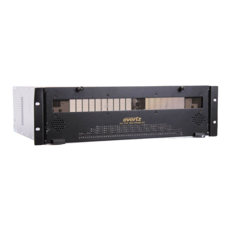
Figure 1-1: Front View of SRF3-64-1x2 Chassis...................................................................................................1
Figure 1-2: Rear View of SRF3-64-1x2 Chassis ...................................................................................................1
Figure 1-3: 1x2 Splitter / 2x1 Combiner.................................................................................................................2
Figure 1-4: 1x4 Splitter / 4x1 Combiner.................................................................................................................2
Figure 1-5: 1x8 Splitter / 8x1 Combiner.................................................................................................................3
Figure 1-6: 1x16 Splitter / 16x1 Combiner.............................................................................................................3
Figure 1-7: 128x128 L Band Matrix Using XRF6 64x64 Routers and SRF3-64-1x2 Modules..............................4
Figure 2-1: Front Panel of SRF3-64-1x2 Chassis .................................................................................................6
Figure 2-2: Rear Panel of SRF3-64-1x2 Chassis..................................................................................................6
Figure 2-3: Front Panel of SRF3-32-1x4 Chassis .................................................................................................7
Figure 2-4: Rear Panel of SRF3-32-1x4 Chassis..................................................................................................7
Figure 2-5: Front Panel of SRF3-16-1x8 Chassis .................................................................................................8
Figure 2-6: Rear Panel of SRF3-16-1x8 Chassis..................................................................................................8
Figure 2-7: Front Panel of SRF3-8-1x16 Chassis .................................................................................................9
Figure 2-8: Rear Panel of SRF3-8-1x16 Chassis..................................................................................................9

