9970-0966/0857-0423
3. Installation
Der Anschluss von Leitungen ist nur im spannungslosen Zustand zulässig!
Achtung! Beim Umgang mit den Bausteinen ist auf Schutzmaßnahmen gegen
elektrostatische Entladung (ESD) zu achten!
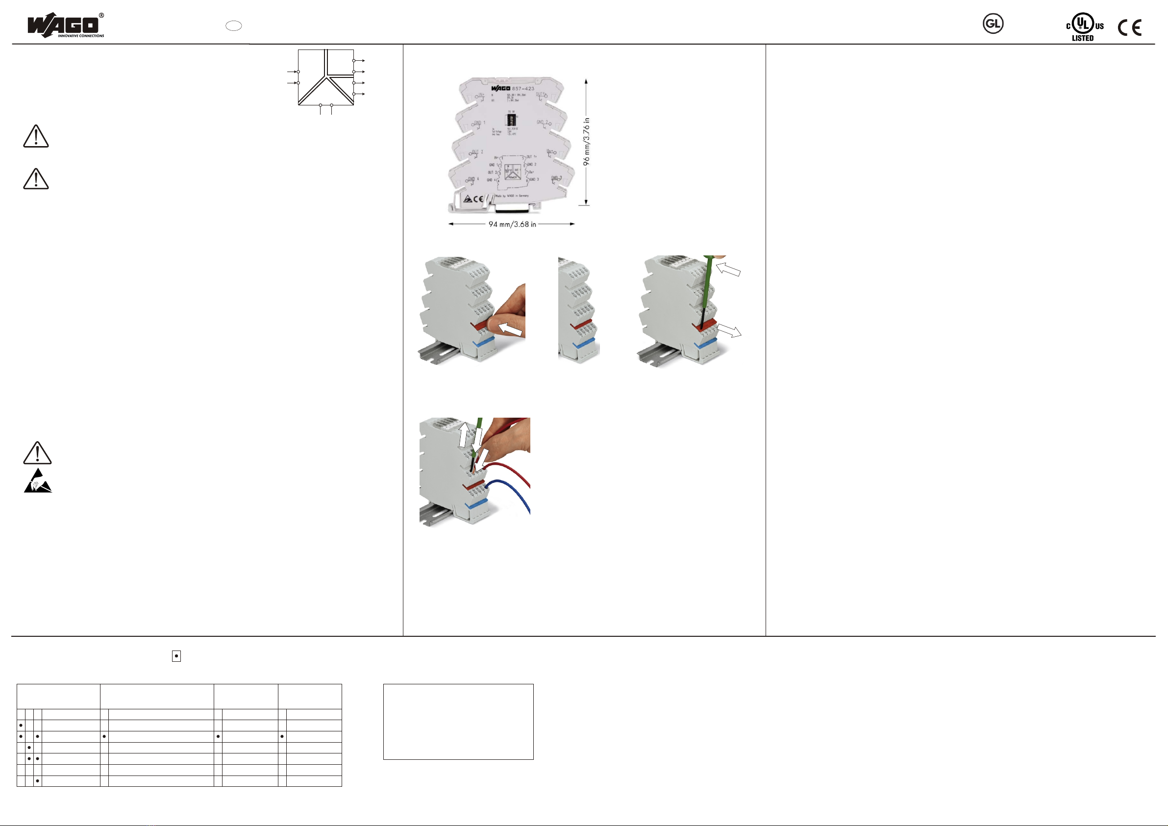
Die Montage der Geräte erfolgt durch werkzeugloses Aufschnappen auf der Tragschiene nach EN60715. Zur
Demontage ist z.B. mittels Schraubendreher der Rastfuß auszulenken und das Gerät in einer
Schwenkbewegung von der Tragschiene zu lösen.
Zur Brückung von Potenzialen können Mehrfachbrücker der Serie 859 (siehe Zubehör) verwendet werden. Die
Brücker sind vor dem Anschluss der Anschlussleitungen zu montieren um eine einfache Montage zu
ermöglichen. Brücker bis zum Anschlag einrasten (siehe Montagehinweise).
Setzen Sie Trennplatten (Artikel-Nr. 209-191) bei sicherer Trennung zwischen zwei benachbarten
Klemmstellen, wenn Baugruppen wechselseitig aufgerastet werden.
Zur sicheren Halterung auf der Tragschiene wird empfohlen, am Anfang und am Ende der Baugruppen einen
Endwinkel (z.B. WAGO 249-116) zu setzen.
Beachten Sie die max. zulässigen Anschlussquerschnitte der Signal- und Versorgungsleitungen.
6. Technische Daten
Eingangssignal 0...20 mA, 4...20 mA
(kalibriert umschaltbar) 0...10 V, 2...10 V
0...5 V, 1...5 V
Eingangswiderstand £50 Ù (I-Eingang)
³100 kÙ(U-Eingang)
Ausgangssignal 2 x (0...20 mA, 4...20 mA)
(kalibriert umschaltbar)
Bürde 2 x 300 Ù
Grenzfrequenz (umschaltbar) < 100 Hz / ca. 1 kHz
Einstellzeit (T ) < 3,5 ms / < 300µs
10-90
Versorgungsspannung U DC 24 V
N
Versorg. Spannungsbereich 19,2 V...30,2 V
Stromaufnahme bei U < 35 mA
N
Übertragungsfehler < 0,1 % vom Endwert
Temperaturkoeffizient 0,01 % / K
Prüfspannung
(Eingang/Ausgang/Versorgung) AC 2,5 kV, 50 Hz, 1 min
zul. Umgebungstemperatur -20 °C...+65 °C
Lagertemperatur -40 °C...+85 °C
Klemmenbreite 6,0 mm / 0,236 in
Anschlusstechnik Klemmen mit CAGE CLAMP® S
2
eindrähtig „e“ 0,08-2,5 mm / AWG 28-12
2
feindrähtig „f“ 0,34-2,5 mm / AWG 22-12
Abisolierlänge 9-10 mm / 0.37 in
Zulassungen CE, UL508 (E175199)
Abweichende Technische Daten bei erweitertem
Versorgungsspannung- und Umgebungstemperaturbereich
Versorg. Spannungsbereich 16,8 V...31,2 V
zul. Umgebungstemperatur -25 °C...+70 °C
Bürde 2 x 250 Ù
Normen
EMV / CE Namur NE21, DIN EN 61326
EN 61000-6-2
EN 61000-6-4
Sichere Trennung Nach DIN EN 61140 durch verstärkte Isolierung
gemäß DIN EN 61010 Teil 1 bis zu AC/DC 300 V bei Überspannungs-
kategorie II und Verschmutzungsgrad 2 zwischen allen Kreisen.
Galvanische Trennung AC/DC 600 V bei Überspannungskategorie II und Verschmutzungsgrad 2
nach DIN EN 61010 Teil 1 zwischen allen Kreisen.
7. LEDs
Die frontseitig sichtbare LED (grün) zeigt folgenden Zustand an:
Grüne LED leuchtet: Betriebsspannung liegt an
in Vorbereitung
= ON
Default-Einstellungen
- Eingang: 0...20 mA
- Ausgang1: 0...20 mA
- Ausgang2: 0...20 mA
- Grenzfrequenz: < 100 Hz
Eingang
DIP Schalter S1 (6-fach)
12
0-20 mA 0-20 mA 0-20 mA
4-20 mA 4-20 mA 4-20 mA
0-10 V
2-10 V
0-5 V
1-5 V
34
Grenzfrequenz Ausgang 1 Ausgang 2
5 6
f ca. 1 kHz
Grenz
f < 100 Hz
Grenz
8. DIP-Schalter Einstellmöglichkeiten
JUMPFLEX Serie 857
Signalverdoppler mit zwei Stromausgängen
857-423
1. Sicherheitshinweise
1.1 Allgemeine Hinweise
Folgende Punkte sind zu berücksichtigen:
- die geltenden Gesetze, Normen und Bestimmungen
- der Stand der Technik zum Zeitpunkt der Installation
- die Bedienungsanleitung
- die Regeln der Technik
- die Tatsache, dass eine Gebrauchsanleitung nur allgemeine Bestimmungen ausführen
kann und dass diese Bestimmungen beachtet werden müssen
Prüfen Sie vor Inbetriebnahme das Gerät auf eventuelle Transportschäden. Bei mechanischen
Beschädigungen darf das Gerät nicht in Betrieb genommen werden.
Die beschriebenen Geräte dienen ausschließlich der Installation durch qualifiziertes Elektro-Fachpersonal und
dürfen nur in elektrischen Betriebsräumen oder in geschlossenen Gehäusen installiert werden. Jegliche
anderweitige Nutzung oder die Nichtbeachtung dieses Anwendungshinweises hat den Verlust der
Gewährleistung bzw. Garantie zur Folge.
Die Geräte dürfen nur in trockenen Innenräumen montiert werden.
Nicht auf oder an leicht entzündlichen Materialien montieren.
Vor Einbau, Betrieb oder Bedienung des Gerätes lesen Sie bitte die vorliegende Anleitung vollständig
und sorgfältig. Im Fehlerfall kann es zur Gefährdung der Anlagensicherheit kommen.
2. Kurzbeschreibung
Der Signalverdoppler wandelt analoge Normsignale, verstärkt, filtert und trennt die analogen Normsignale
galvanisch voneinander. Das Gerät verfügt über eine 3-Wege-Trennung mit einer Prüfspannung von 2,5 kV.
Der Signalverdoppler 857-423 überträgt das konfigurierbare Eingangssignal (0...10V, 2...10V, 0...20mA,
4...20mA, 0...5V sowie 1...5V) in zwei analoge Stromausgänge, die unabhängig voneinander zwischen 0...20
mA und 4...20 mA eingestellt werden können.
Die Versorgungsspannung des Gerätes beträgt 24 V DC, die über seitliche Kammbrücker schnell und
kostengünstig gebrückt werden kann.
5. Montagehinweise
4. Abmessungen
Brücker bis zum Anschlag
einstecken
Leiter anschliessen
Brücker gesteckt Brücker entfernen
www.wago.com
Technische Änderungen vorbehalten
D
1
2
3
IN
OUT1
OUT2
Power
I
I
U,I
IN+ (1) OUT1 (5)
GND1 (2) GND2 (6)
OUT2 (3) Us+ (7)
GND4 (4) GND3 (8)