AutomationDirect DL305 User manual

Errata Sheet
Page 1 of 1
Product Family:DL305
Manual Number D3-DCU-M
Revision and Date 1st Edition, Rev. A; June, 1998
Date: April 2018
This Errata Sheet contains corrections or changes
made after the publication of this manual.
Errata Sheet
Change to Page 15. Address Switch
The second sentence in the Address Switch section is incorrect. There is no BCD (Binary Coded Decimal) involved with the
addressing.
Instead of “The decimal address is set in BCD (Binary Coded Decimal) format with valid addresses from 1 to 90 decimal.” the
sentence should be:
“The decimal address is set from 1 to 90 decimal.”
Change to Page 19. Troubleshooting
For the “DIAG off” entry in the troubleshooting table, the cause listed is “DCU is defective”. Two other possible causes are a
defective CPU module or base.

111
Introduction
This manual is designed to allow you to quickly install your DL305 Data
Communications Unit (DCU). This is the only manual you will need if your are using
the DCU as an interface for the
Direct
SOFT programming package or, as a
communications port for an operator interface. If you plan on using the DCU as a
slave interface on a
Direct
NET network, you should read the
Direct
NET manual
first. The
Direct
NET manual provides detailed descriptions of the network
configuration and protocol that is necessary to control communications with the
DCUs.
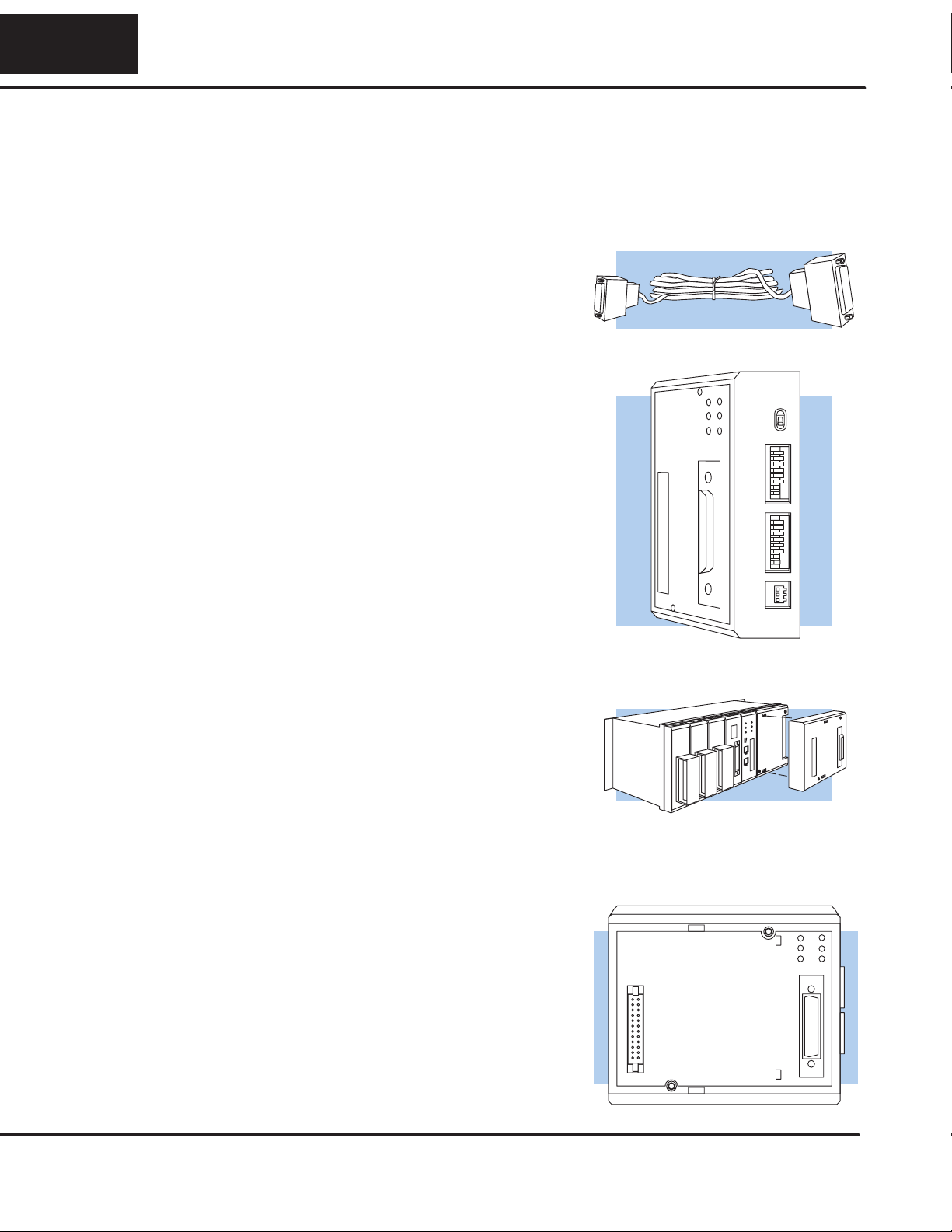
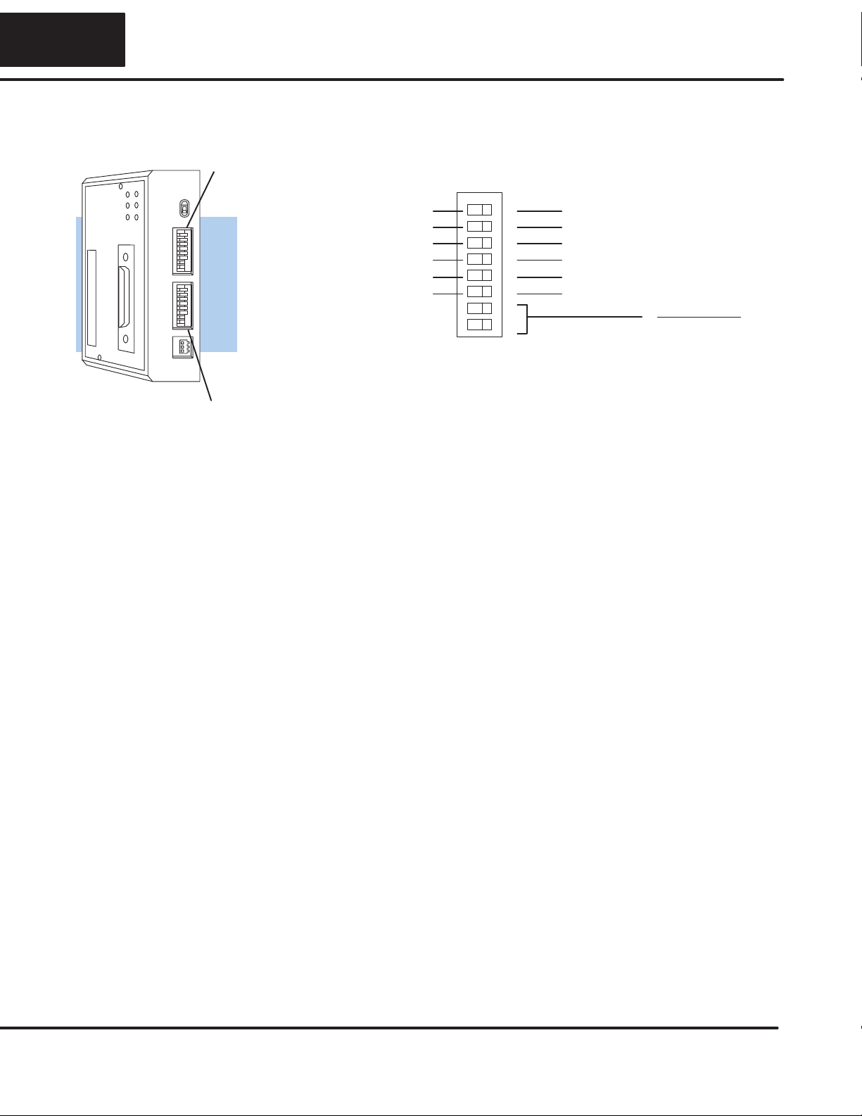
The following diagram shows the major DCU components. The address selection
switches and the communication dipswitches are of special importance. Also, there
are two versions of the DCU RS232C and RS422. You can use RS232C/RS422
converters with these units, but it is generally easier to use the version that is best
suited for your application.
Online/Offline Switch
RS232C/RS422
Communication Port
DIP Switches for communications
and Protocol Parameters
Handheld Programmer
Connector
RUN
BATT
CPU
DATA
DIAG
PWR
On when PLC is in
Run Mode
On when PLC battery
needs replacing
On when a fatel error
has occured in the CPU.
On (flashing) when data is
being transmitted
On when internal diagnostic tests
have complete and passed.
On when base power is on. If an external
power supply is used, both base power
and the external supply must be provided
for this indicator to be on.
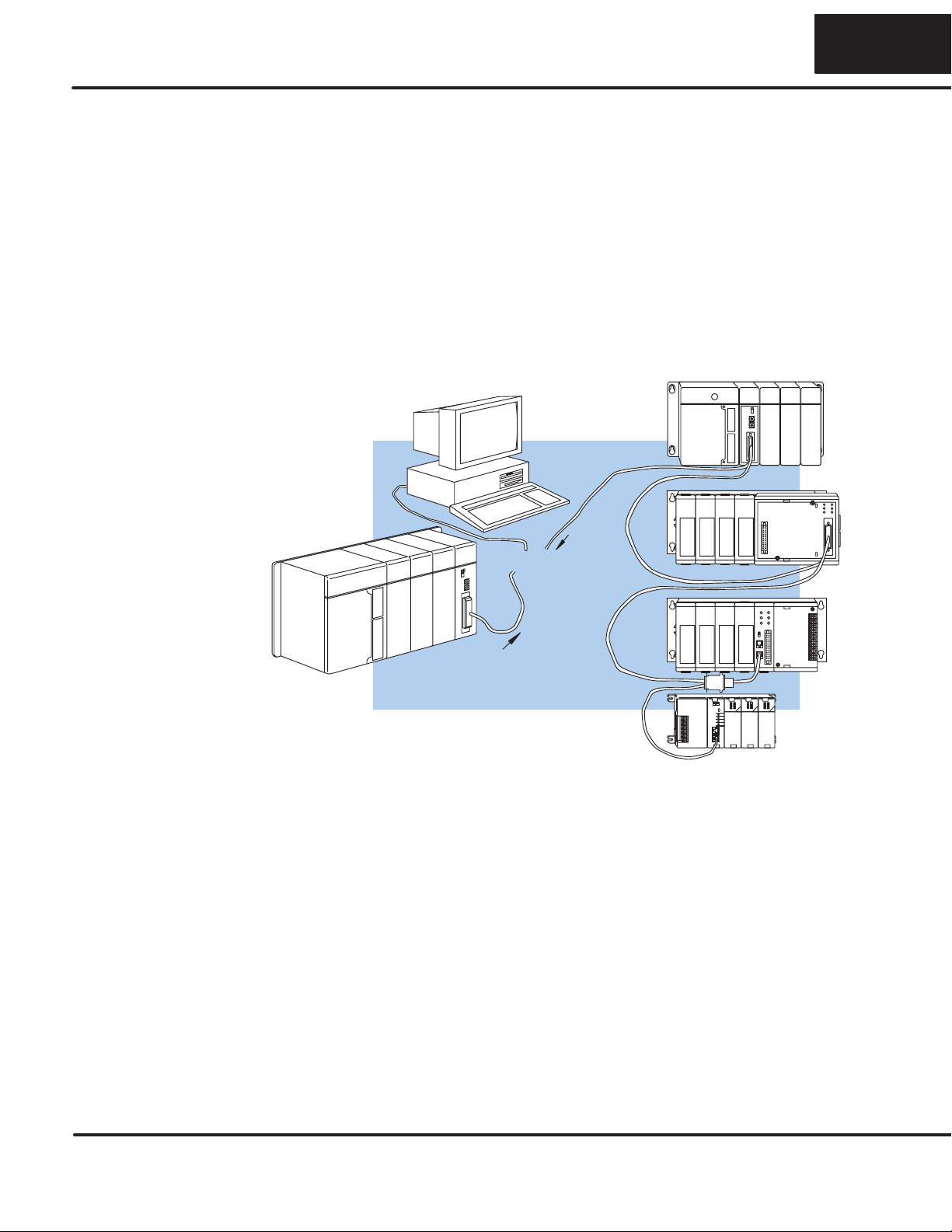
TheDL305 DataCommunications Unit(DCU) isa communicationsinterface forthe
DL305 family of Programmable Logic Controllers (PLCs). This module is primarily
used for two reasons.
SAs a general purpose communications port to connect a personal
computer or operator interface.
SAs a network interface to a
Direct
NET network.
The following pages provide an overview of these uses, along with the information
you need to connect the DCU.
Is this the right
manual for you?
DCU Hardware
Overview
DCU Uses

2
How can I use the DCU?
As a communication port, you can connect various devices, such as operator
interfaces or personal computers.
Since the DCU does not require any programming, you can simply set the DCU
communication parameters, connect the appropriate RS232C or RS422 cables,
and start programming or transferring data.
DL305 with DCU
As a General
Purpose
Communication
Port
333
The DCU can be used as a network interface for applications that require data to be
shared between PLCs, or between PLCs and an intelligent device (such as a host
computer). The DCU easily connects to
Direct
NET. This network allows you to
upload or download virtually any type of system data including Timer/Counter data,
I/O information, and Register memory information.
As part of a PLC Network Slave — The DCU can only be used in a DL305 PLC
stationthatisservingasanetworkslavestation.Inthiscase,theDCU“listens”tothe
network for any messages that contain the DCU’s address. The DCU deciphers the
network commands, carries out the request to read or write data, and sends
confirmation and/or information to the master station.
Request
Direct
NET Slaves
Slaves respond to
the master’s request
Response
or
Direct
NET Masters
As a
Direct
NET
Interface
4
How can I connect the DCU? – Four Simple Steps
Complete the following steps to connect
the DCU.
STEP 1. Build the communication cable
that fits your needs.
STEP 2. Set the DCU switches. (Baud
rate, parity, etc.)
STEP 3. Install the DCU.
STEP 4. Verify correct operation.
Cable
Set the Switches
Install the DCU
Check the LEDs

555
Step 1: Build the communication cable
There are several considerations that help determine the type of cable needed for
your DCU application.
1. Will the DCU be physically connected in a point-to-point configuration or
multi-drop configuration?
2. What electrical specification is best for your application? RS232C or
RS422?
3. What is the cable schematic?
4. What are the relevant cable specifications?
5. What installation guidelines are necessary?
6. Do you just need a quick test cable?
The next few pages discuss these considerations in detail. If you already know the
type of cable that is needed, the cable schematics are included on pages 8 and 9.
Things to Consider

6
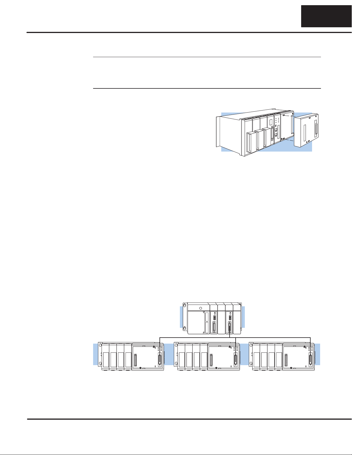
Depending on the version of DCU you have, you can use the DCU in either a
point-to-point or multi-drop configuration. A point-to-point connection only has two
stations, a master and a slave. Use the point-to-point configuration to connect a
personal computer, an operator interface, or an intelligent device to a single DCU.
You should also use this configuration when you want to connect a
Direct
NET
master station to a single
Direct
NET slave station.
Use the multi-drop configuration to connect one master to two or more slaves.
Point to Point
DL405 Master DL305 PLC Slave
DCM
DL305 with DCU
DCU
Consideration 1:
Physical
Configuration

777
ThereisaspecificmodelofDCUforbothRS232CandRS422communication.Your
application and configuration choice will help determine which electrical
specificationisbestforyou.Ifyouareusingmulti-drop,youshoulduseRS422.(You
can use RS232C/RS422 converters if necessary.) If you are using point-to-point,
you may have a choice between RS232C and RS422.
YoucanuseRS232Cifthecablelengthislessthan50feetandifthecablewillnotbe
subjected to induced electrical noise that is commonly found near welders, large
motors, or other devices that create large magnetic fields.
You should use RS422 for all other applications. RS422 allows longer cable
distances (up to 3300 feet) and provides higher noise immunity.
Direct
NET Slaves
Direct
NET
Masters
DCM
Multi-drop
or
The following diagram shows the port pinouts for the two types of DCUs.
Pin Signal Definition
1 Not connected
2 Not connected
3 Not connected
4 Not connected
5 Not connected
6 Not connected
7 Logic ground 0V
8 Not connected
9 Not connected
10 RS422 RTS +
11 RS422 RTS –
12 RS422 CTS +
13 RS422 CTS –
Pin Signal Definition
14 RS422dataout+
15 RS422data out –
16 RS422 data in –
17 RS422 data in +
18 Not connected
19 Not connected
20 Not connected
21 Not connected
22 RS422data out+
23 RS422data out –
24 RS422data in –
25 RS422 data in +
Pin Signal Definition
1 Not connected
2 RS232C TXD
3 RS232C RXD
4 RS232C RTS
5 RS232C CTS
6 Not connected
7 Logic ground 0v
8 Not connected
9 Not connected
10 Not connected
11 Not connected
12 Not connected
13 Not connected
Pin Signal Definition
14 Not connected
15 Not connected
16 Not connected
17 Not connected
18 Not connected
19 Not connected
20 Not connected
21 Not connected
22 Not connected
23 Not connected
24 Not connected
25 Not connected
D3–232–DCU Port Pinouts
114
D3–422–DCU Port Pinouts
Consideration 2:
Electrical
Specification
RS232C or RS422

8
Thefollowingcableschematicsareappropriateformostapplications.Youmayhave
to combine some of these examples to design a cable that meets your exact
application requirements.
DL305 DCU
DL405 DCM
DL405 DCM to DCU (RS422)
DL405 DCM
2 TXD
3
4
5
RXD
RTS
CTS
3 RXD
2
4
5
TXD
RTS
CTS
AB
AB
7 GND 7 GND
2 TXD
3
5
1
4
RXD
GND
DCD
DTR
2 TXD
3
7
4
5
RXD
GND
RTS
CTS
6 DSR
7RTS
8 CTS
7 GND
10
11
12
13
+RTS
–RTS
+CTS
–CTS
7 GND
10
11
12
13
+RTS
–RTS
+CTS
–CTS
14 +OUT
15 –OUT 17 +IN
16 –IN
16 –IN 15 –OUT
17 +IN 14 +OUT
Personal Computer to DCU (RS232C)
DL405 DCM to DCU (RS232C)
AB
AB
DL305 DCU
DL305 DCU
Master
DL305
DCU
Slave
DL405
DCM
AB
Master
DL305
DCU
Slave
PC
AB
Master
DL305
DCU
Slave
DL405
DCM
3 RXD
2
7
4
5
TXD
GND
RTS
CTS
2 TXD
3
7
4
5
RXD
GND
RTS
CTS
6 DCD
8 DTR
20 DSR
AB
Master
DL305
DCU
Slave
PC
9–pin
Connector
25–pin
Connector
Consideration 3:
Cable Schematics

999
DL405
CPU Port
DL405
CPU Port
DL405
CPU Port
Multi-drop, DL405 DCM to DL305DCU and
DL405PLC Slaves (RS422)
7 GND
10
11
12
13
14
15
16
17
22
23
24
25
+RTS
–RTS
+CTS
–CTS
+OUT
–OUT
–IN
+IN
+OUT
–OUT
–IN
+IN
7 GND
10
11
12
13
14
15
16
17
22
23
24
25
+RTS
–RTS
+CTS
–CTS
+OUT
–OUT
–IN
+IN
+OUT
–OUT
–IN
+IN
7 GND
10
11
12
13
14
15
16
17
22
23
24
25
+RTS
–RTS
+CTS
–CTS
+OUT
–OUT
–IN
+IN
+OUT
–OUT
–IN
+IN
7 GND
19
18
11
23
14
16
10
9
+RTS
–RTS
+CTS
–CTS
+OUT
–OUT
–IN
+IN
A
BCD
Master Slave Slave Slave
ABCD
Termination Resistors*
2 TXD
3
5
1
4
RXD
GND
DCD
DTR
3 RXD
2
7
20
25
TXD
GND
DTR
+5V
6 DSR
7RTS
8 CTS
7 GND
10
11
12
13
14
15
16
17
+RTS
–RTS
+CTS
–CTS
+OUT
–OUT
–IN
+IN
7 GND
10
11
12
13
14
15
16
17
22
23
24
25
+RTS
–RTS
+CTS
–CTS
+OUT
–OUT
–IN
+IN
+OUT
–OUT
–IN
+IN
7 GND
10
11
12
13
14
15
16
17
22
23
24
25
+RTS
–RTS
+CTS
–CTS
+OUT
–OUT
–IN
+IN
+OUT
–OUT
–IN
+IN
A
B
Termination Resistor*
RS422 Multi-drop requires termination resistors (see installation)
Multi-drop, PC to DL305DCU and DL405PLC
Slaves (RS422)
Termination Resistor*
DL405
DCM DL305
DCU DL305
DCU DL405
CPU Port
DL305
DCU DL305
DCU
DL405
DCM
Master Slave Slave Slave
ACDE
PC
DL305
DCU DL305
DCU
FA–UNICON Convertor
B
CDE
DL305
DCU DL305
DCU
7 GND
19
18
11
23
14
16
10
9
+RTS
–RTS
+CTS
–CTS
+OUT
–OUT
–IN
+IN
10
Although many types of cables may work for your application, we recommend you
use a cable that is constructed to offer a high degree of noise immunity. A cable
constructed equivalent to Belden 9855 should be sufficient. The following
specifications should be used as a guideline.
Structure Shielded, twisted-pair. . . . . . . . . . . . . . . . . . . . . . . (RS232C only uses two wires and a ground)
Conductor size 24 AWG or larger. . . . . . . . . . . . . . . . . .
Insulation Polyethylene. . . . . . . . . . . . . . . . . . . . . . .
Shield Copper braid or aluminum foil. . . . . . . . . . . . . . . . . . . . . . . . . .
Impedance 100W@ 1MHz. . . . . . . . . . . . . . . . . . . . . .
Capacitance 60pf / meter or less. . . . . . . . . . . . . . . . . . . .
Your company may have guidelines for cable installation. If so, you should check
those before you begin the installation. Here are some general things to consider.
SDon’t run cable next to larger motors, high current switches, or
transformers. This may cause noise problems.
SRoute the cable through an approved cable housing to minimize the risk
of accidental cable damage. Check local and national codes to choose
the correct method for your application.
SConsider redundant cabling if the application data is critical. This allows
you to quickly reconnect all stations while the primary cable is being
repaired.
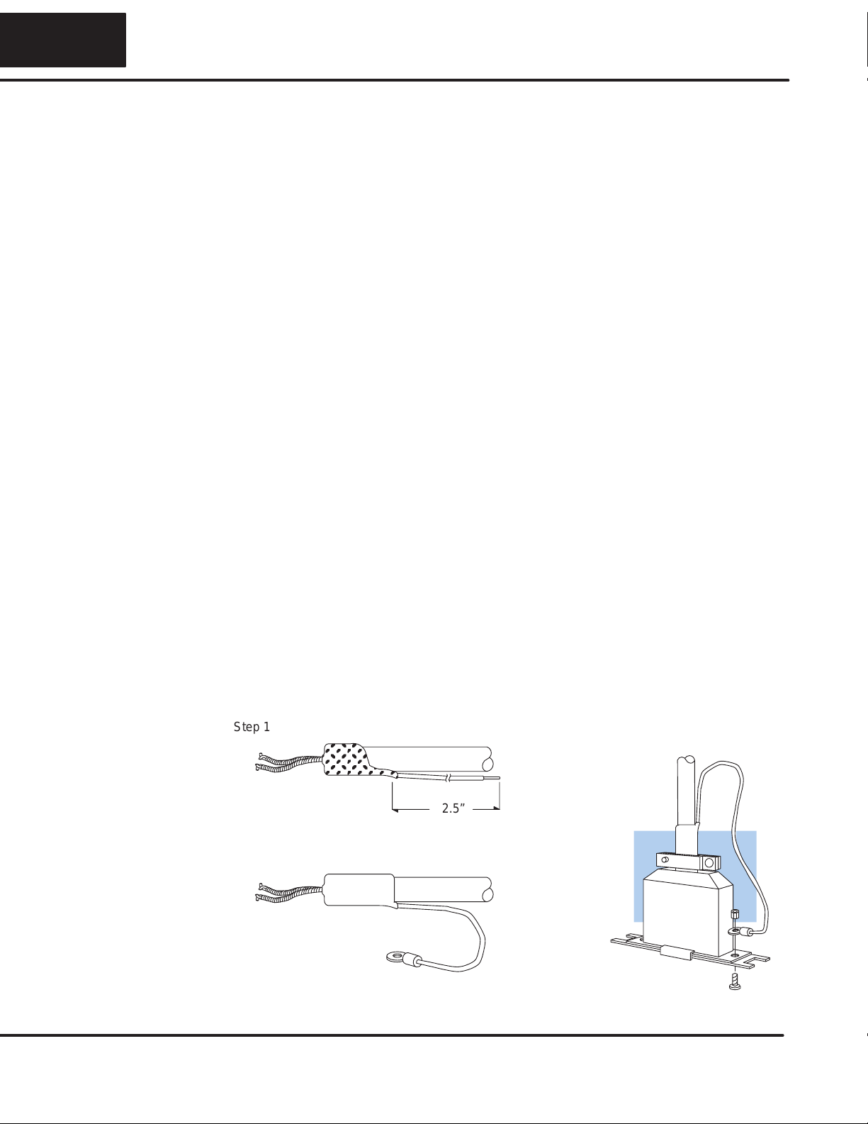
Cable Shield Grounding — It is important to ground the cable shield to minimize
the possibility of noise. The preferred method is to connect one end (preferably the
receiver end) of the cableshield to the connector housing.If noise problems arestill
present and you have a good earth ground for the cabinet, you should connect one
end of the shield to the cabinet earth ground.
Don’t
ground both ends of the shield
because this will create induced noise on the cable.
ÎÎÎÎÎ
ÎÎÎÎÎ
2.5”
Step 1: Strip back about 2.5” of the shield.
Step 2: Crimp a ring connector onto the shield.
Step 3: Secure the shield to the
connector shell.
Consideration 4:
Cable
Specifications
Consideration 5:
Installation
Guidelines

11 1111
Multi-drop Termination Resistors — It is important you add termination resistors
at each end of the RS422 line. This helps reduce data errors during data
transmission. You should select resistors that match the cable impedance. For
example,atypical22AWGsolidconductorcablewith4.5twistsperfoothasatypical
impedance of about 120W.
There are two ways to actually connect the resistors.
SLine-to-Line — this method balances the receive data lines (IN+ and
IN–) and requires one resistor at each end of the line. (The cable
diagrams we’ve provided show this method, but you can use either.)
SLine-to-Ground — this method also balances the receive data lines, but
common mode noise rejection is improved significantly. This method
requires two resistors at each end of the line. Also, since there are two
resistors, the sum total of both resistors should match the cable
impedance.
The following diagram illustrates the two options.
7 GND
10
11
12
13
14
15
16
17
22
23
24
25
+RTS
–RTS
+CTS
–CTS
+OUT
–OUT
–IN
+IN
+OUT
–OUT
–IN
+IN
7 GND
19
18
11
23
14
16
10
9
+RTS
–RTS
+CTS
–CTS
+OUT
–OUT
–IN
+IN
Master
120 ohm
Resistor
Last Slave
120 ohm
Resistor
Slave
Line-to-Line Termination
7 GND
10
11
12
13
14
15
16
17
22
23
24
25
+RTS
–RTS
+CTS
–CTS
+OUT
–OUT
–IN
+IN
+OUT
–OUT
–IN
+IN
7 GND
19
18
11
23
14
16
10
9
+RTS
–RTS
+CTS
–CTS
+OUT
–OUT
–IN
+IN
Master
62 ohm
Resistors
Last SlaveSlave
62 ohm
Resistors
Line-to-Ground Termination
Terminate
at Master
Terminate
at Last Slave

12
PLC
Direct
offers a Universal Cable Kit (part number FA–CABKIT). This cable kit
allows you to connect various types of
Direct
LOGICproducts with an RS232C
cable in a matter of minutes. The kit consists cable (phone cable with male plugs
already attached) and several specially wired connectors. The special connectors
are a D-sub style with built-in female phone jacks. The kit includes a wide variety of
the special connectors so you can use one kit to easily connect products from the
different
Direct
LOGICfamily of products. To use the kit with the DCU, just follow
these steps.
1. Plug the appropriate D-sub connector onto the DCU.
2. Plug the appropriate D-sub connector onto the other device you are
connecting to the DCU.
3. Connect the 50 foot cable to the two D-sub connectors.
WARNING: This cable is suitable for quick testing situations and should not
be used in actual applications. This cable is not shielded and is highly
susceptible to electrical noise. Electrical noise can cause unpredictable
operation that may result in a risk of personal injury or damage to equipment.
Use the cable specifications described earlier in this manual to select a cable
suitable for actual applications.
9 Pin
Build A Test Cable In 30 Seconds
1. Attach Universal Cable Adapter to the DCU
2. Attach another Universal Cable Adapter to the
Device which will connect to the DCU
3. Attach the Universal Cable
Universal 9 pin
D–sub connector Universal 25 pin
D–sub connector
Consideration 6:
A Quick Test Cable
13 1313
Step 2: Set the DCU switches
The device(s) connected to the DCU will help you determine the appropriate switch
settings.
Ifyou’reconnectingtheDCUtoacomputeroroperatorinterface,justsettheDCUto
match those communication parameters. Check the documentation that came with
your computer or operator interface to determine the available communication
parameters.
You’ll need to know the following things.
SBaud rate
SParity settings
SProtocol
NOTE: Some operator interfaces support multiple protocols. Make sure your
operator interface uses one of the following protocols.
S
Direct
NET (DL330, DL340, D3–232–DCU, or D3–422–DCU)
SHostlink (TItor SimaticrTI325, –330, -335, 305–03DM, or 305–02DM)
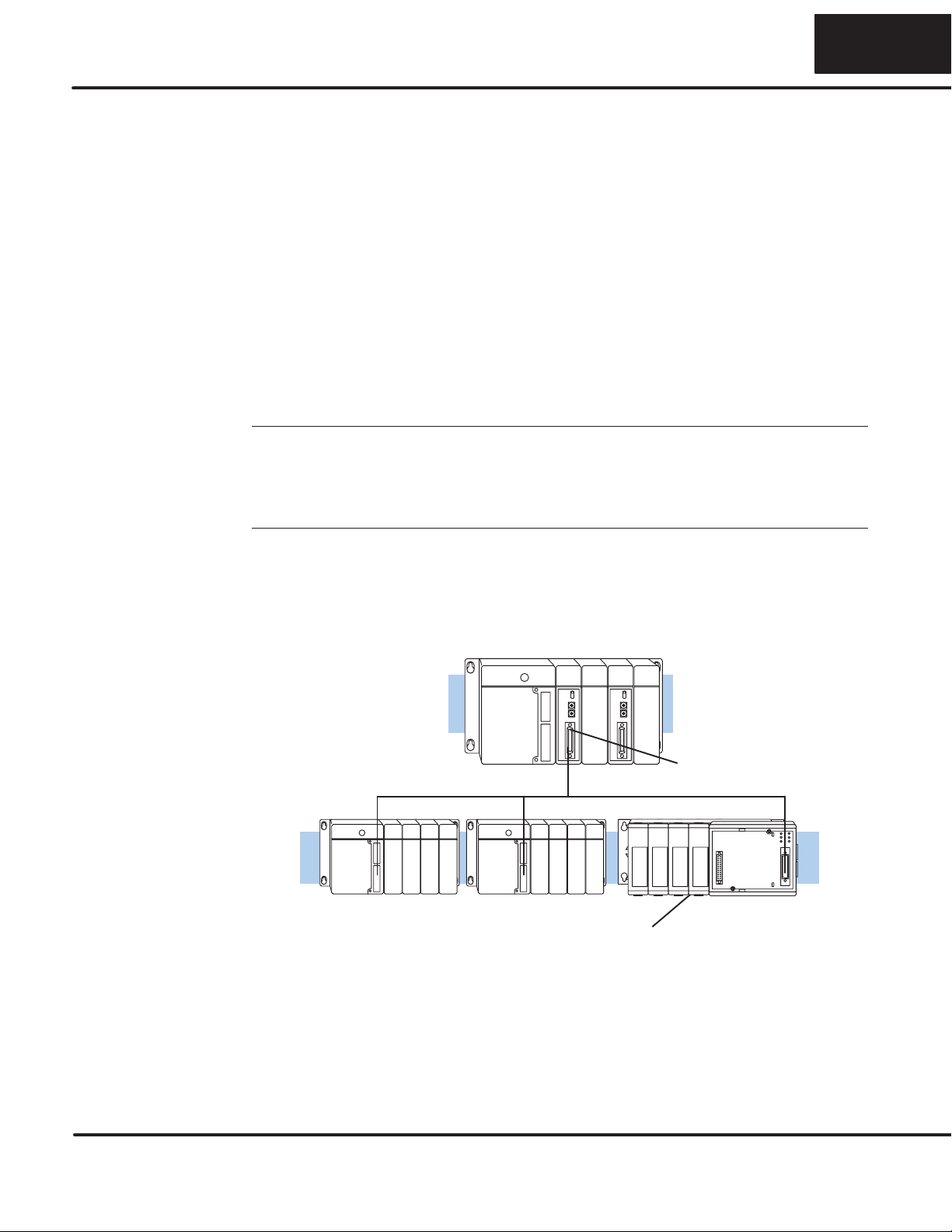
The DCU can only be used as a slave station, so set the switches to match the
communications parameters for the master station.
DL405 PLC Master - Slave Network
DCM as Master
DL305 DCU as Slave
Host Computer or
Operator Interface
Connection
Direct
NET Interface
Connection
14
There are two banks of switches located on the side of the DCU that are used to set
the communications and protocol parameters. The following diagram shows the
locations and setting options.
Baud 1 2
300 OFF OFF
1200 ON OFF
9600 OFF ON
19200 ON ON
Baud Rate
ODD Parity Switch Positions
Self Test NO Parity
Set to OFF
ON OFF
Block 11
2
3
4
5
6
7
8
10 ms Delay Time No Delay
PGM Mode at power up Run Mode at power up
Not Used Not used
ASCII Mode HEX Mode
Baud Rate: The first two positions on block 1 are used to set the baud rate for the
DCU. There are four baud rate selections available ranging from 300bps to
19.2Kbps.Allstationsmusthavethesamebaudratebeforethecommunicationswill
operate correctly. Usually, you should use the highest baud rate possible unless
noise problems appear. If noise problems appear, try reducing the baud rates.
Parity: Position 3 on block 1 selects between the two parity options, odd or none. If
you’re using all
Direct
LOGICequipment, you can use odd parity. Odd parity uses
eleven bits total (1 start bit, 8 data bits, 1 stop bit, and 1 parity bit.) Some devices
require no parity, which uses only 10 bits (1 start bit, 8 data bits, and 1 stop bit.)
Self-Test: Position 4 on block 1 selects the factory self-test and should always be
switched off. If the self-test is on, the DCU will not operate correctly.
Response Delay Time: Position 5 on block 1 sets the response delay time. This
sets how long the DCU will wait before it responds to each component of a
Direct
NETcommunicationrequest. Ifyou’re usingall
Direct
LOGICequipment, a
response delay is not required and you should turn off the switch.
The DCU may respond too quickly for some devices, such as telephone or radio
modems. If you encounter this problem, turn on the delay switch to provide a 10 ms
delay. If this still does not work, check your device manual to see if the device
requires more than a 10 ms delay.
Mode at Power-up: Position 6 on block 1 allows you to select the CPU operating
mode when system power is supplied. If the switch is turned on, the CPU
automatically enters Program mode when power is supplied. If the switch is off, the
CPU automatically enters Run mode when power is supplied.
ASCII/HEX Mode: Position8 onblock 1selects betweenASCII andHEX modesof
data representation. If you want the fastest communication possible, use HEX
mode.Thedifferenceisinthewaythedataisrepresented.Thesamedataistwiceas
longinASCII format,so ifthere’s moredata, ittakes longerto transfer. Ifyou havea
deviceonthenetworkthatrequiresASCIImode,thensettheswitchforASCIImode,
otherwise, use HEX mode.
DCU
Switch Settings
Block
1
Block
2

15 1515
As you examined the diagrams at the
beginningofthismanualyoumayhavenoticed
you can still connect a Handheld Programmer
even when there is a cable connected to the
DCU. There’s an Online/Offline switch on the
side of the unit that determines which
connection has control of the CPU.
In the Offline position, this switch logically
disconnects the DCU from the network (just as
if you pulled the cable from the 25-pin
connector.) Once this switch is moved to the
Offline position, the DCU will not communicate
with the network, and the Handheld
Programmer can communicate with the CPU.
If you move the switch to the Online position,
the DCU will communicate with the network,
but not until the master sends a request for
communication. This does not operate like the
reset switch on many personal computers.
NOTE: You cannot use the Handheld
Programmer if the switch is in the Online
position.
TheDCUstationaddressissetbythesecond
switch block, which is located on the side of
the unit. The decimal address is set in BCD
(Binary Coded Decimal) format with valid
addressesfrom1to90decimal.Forexample,
to set an address of 10, you should turn on
switches 4 and 2.
The addresses do not have to be sequential,
buteach stationmusthave auniqueaddress.
NOTE: The DCU address switch settings are
only read at power up. If you’ve want to
change the address and the DCU is already
up and running, you’ll have to cycle the
system power to initialize the change.
Block 2
1
2
3
4
5
6
7
864
32
16
8
4
2
(Binary Value)
1
Not used
ON OFF
Online / Offline
Switch
Address Switch
The highlighted
sentence is incorrect.
It should read: "The
decimal address is set
from 1 to 90 decimal.

16
Step 3: Install the DCU and start the communications
The DCU requires 500 mA of +5V base power. Make sure you will not exceed the
available base power budget by installing the DCU.
WARNING: Exceeding the base power budget may cause unpredictable
systemoperation that can result in personal injury or equipment damage.See
the DL305 User Manual for details on power budget calculations.
On the back of the DCU is a switch to select if it will receive power form the base
(INT–internal position)or froman externalpower source(EXT –externalposition).
If there appears to be a power budget problem, use the external power source
option. The DCU is shipped with a three pin pigtail which should be used to connect
theexternalpowersource.Thepigtailconnectstothebottomoutletonthesideofthe
DCU.
Green
(G)
Black
(OV)
Wh te
(5V)
PWR
EXT
INT Set
Sw tch
to reflect
power
source
If you use an external power supply, you must provide an external ground
connection for the DCU. The following diagram shows how the external power
sources are connected.
5V
Power
Supply +
-5V
Power
Supply +
-5V
Power
Supply +
-
RS422/422 Amp or
RS422/432 Convertor
To host or
Tw sted Pa r slave stat on
GND
Check the Power
Budget
17 1717
Use the following procedures to install the DCU.
WARNING: Always disconnect the system power before installing or
removing any system component. Also,
do not
install a DCU while the CPU is
in RUN mode. This may cause unpredictable operation which can result in a
risk of of electrical shock, personal injury, or equipment damage.
1. Set the power source switch, located
on the rear of the DCU, to the correct
position.
2. Carefully align the connector on the
rear of the DCU with the CPU
connector and gently push the DCU
ontotheCPU.(Iftheconnectorsarenot
aligned properly, you can bend the
connector pins.)
3. Secure the DCU to the system with the
two mounting screws.
Make sure you have all the cables connected and that all the network devices have
the same communication parameters (baud rate, parity, etc.)
Connect the cables and follow the procedures outlined in the documentation that
camewith yourhostcomputersoftwareor operatorinterface.You’ll haveto execute
your host or operator interface program before the communications can begin. For
example, if you’re using
Direct
SOFT, you can just specify the station address and
start working!
Sinceyou canonlyusetheDCU inaslave station,there hastobe anetworkmaster
that issues the communication requests. The PLC master station must contain an
RLL communications program . (See the
Direct
NET Manual or the DL405 User
Manualfordetails ontheRXandWXinstructions.) ThemasterstationCPUmustbe
in Run mode in order to execute the communications program. The slave station
CPUs do not absolutely have to be in Run mode because the DCU will still transfer
the data. Whether you put the slave stations in Run mode depends on your
application requirements.
Install the DCU
Connect the
Cables
If you’re using an
Operator Interface
or Computer...
If you’re using
Direct
NET...

18
Step 4: Verify that it’s working correctly
Check the DCU indicators to verify the DCU is operating correctly. The following
diagram shows the proper indicator conditions.
RUN
BATT
CPU
DATA
DIAG
PWR
On when PLC is in
Run Mode
On when PLC
battery needs
replacing
On when a fatel
error has occured in
the CPU.
On (flashing) when
data is being
transmitted
On when internal
diagnostic tests are
complete and have
passed.
On when base
power is on. If an
external power
supply is used, both
base power and the
external supply must
be provided for this
indicator to be on.

19 1919
Troubleshooting
If the DCU does not seem to be working correctly, check the following items.
1. Cable and connections. Incorrectly wired cables and loose connectors
cause the majority of problems. Verify you’ve selected the proper cable
configuration and check to see the cable is wired correctly.
2. Dipswitch settings. Make sure you’ve set the DCU to match the
communication parameters required by the master station (DL405 DCM,
operator interface or host computer).
3. Incorrectprotocol.Makesureyouroperatorinterfaceorpersonalcomputer
software can use the
Direct
NET, Hostlink/CCM2 protocol.
4. Communicationsprogram. Checkthecommunicationsprogram forerrors.
Consult the
Direct
NET Manual or the manuals that came with your host
computer software or operator interface for details.
The following table provides additional troubleshooting details.
Indicator Status Possible Cause Corrective Action
PWR off PLC power is disconnected
DCU is not connected to the CPU
properly
DCU external power source
(if used) is not connected
DCU is defective
Check the PLC source power.
Make sure the DCU is securely
fastened to the CPU and no
connector pins are bent.
Check the external power source.
Replace the DCU
DIAG off DCU is defective Replace the DCU
DATA does not flash during
communications Loose or incorrectly wired cable
Online / Offline switch is in the
Offline position
Communications program is not
correct
Check the cable connections and
pinouts.
Set the switch to Online.
Check the master
communications program. Verify
the address, amount of data, and
data type are correct.
For "DIAG off", two
other possible causes
are a defective CPU
module or base.
Other manuals for DL305
1
Table of contents
Popular Recording Equipment manuals by other brands


ADInstruments
ADInstruments PowerLab C Series owner's guide

Erica Synths
Erica Synths fusionbox user manual

National Instruments
National Instruments NI 9860 Getting started guide

Roland
Roland TR-707 owner's manual

Extron electronics
Extron electronics RGB 202 Rxi VTG user manual

EpiSensor
EpiSensor ZHM-21 Install Sheet


