Manual EIM 316/336 interface application for setup and conguration of MMIMyK
4DKRCC.PS.RQ0.C2.02 / 520H8422 © Danfoss A/S (AC-MCI/sw), 2014-03
5. Starting the
application
The MyK will startup in its Bios menu if no
application has previously been loaded. From
this menu it is possible to load the applications
that are stored on the MyK, either in its internal
or external memory. Please refer also to the
MMIMyK software download guide.
Select Application – Appl.Load, then select the
disc that the application is stored on, 0:/ (internal
memory) or 1:/ (SD/MMC card). Select the folder
containing the application and press the enter
button. The application should load automati-
cally and will startup after a few seconds.
The next time the MyK is powered, it will start the
application automatically. To enter the bios menu
again, press the Esc and enter buttons at the same
time, and keep them pressed for a few seconds,
until the MyK enters the bios menu. From here it is
possible to load another application.
6. Using the
application
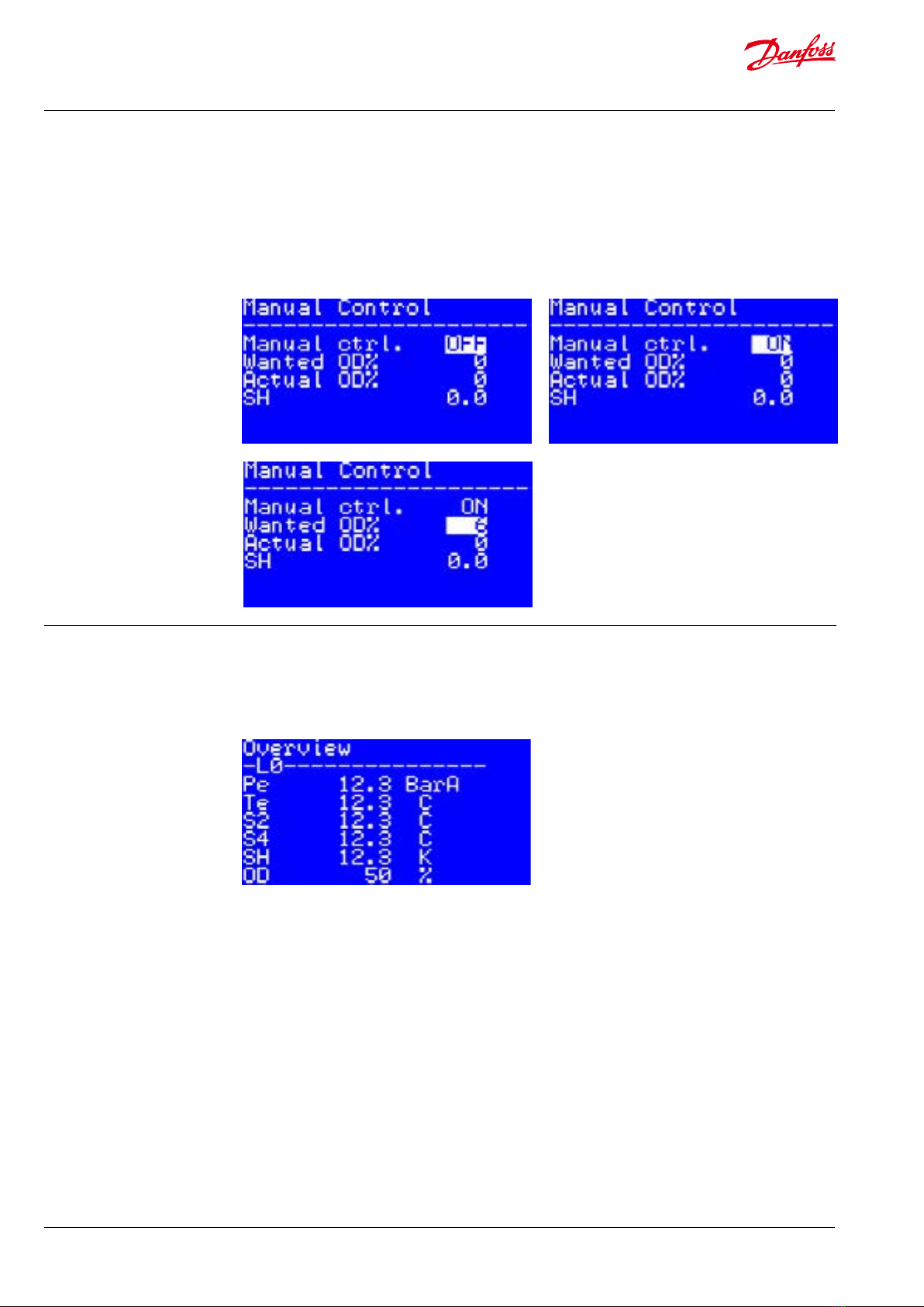
6.1 The main screen
The main screen shows the current superheat (SH)
and opening degree (OD) in large characters.
If the main switch is o, this will be shown with
the characters OFF in large characters in the
upper right corner. If the main switch is on, the
currently active superheat reference is shown in
the upper right corner instead.
If an alarm is present, this is indicated by the
word “ALARM” to the right of the opening
degree. If the unit is in manual control mode, this
is indicated with the word “MAN”.
Pressing enter will give access to the main menu.
Pressing escape will give access to the alarm screen.
If the MyK does not recognize that it is con-
nected to an EIM 336, it will beep to indicate
that it is in alarm.
On the main screen press enter and go to
“Parameters-> MyK setup-> System”.
Under “Active EIM Addr”, set the correct ID of
the EIM 336 you want to connect to. Under
“Serial baud rate (MB)” set the baud rate to the
Setting up the MYK to
specic EIM 336 unit
address.
correct baud rate (default for EIM is 192 i.e. 19200
Baud) then after set the correct serial settings
under “Serial settings (MB)”, (default value for EIM
336 is 8E1 i.e. 8 data bits, even parity and 1 stop
bit). The MyK should now able to connect with
the EIM 336.