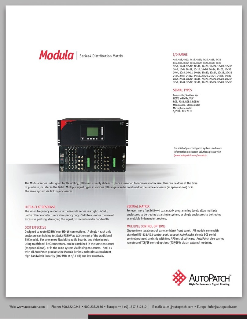
AutoPatch 1Y Series Assembly instructions

1Y Series Distribution
Matrices
User Reference Manual
CPU Version 5.0
Document Version
A4

Notices
AutoPatch © 1994, 1997, 1998 all rights reserved. No part of this publication may be reproduced,
stored in a retrieval system, or transmitted, in any form or by any means, electronic, mechanical,
photocopying, recording, or otherwise, without the prior written permission of AutoPatch. Copy-
right protection claimed extends to the AutoPatch 1YDM hardware and software and includes all
forms and matters, copyrightable material and information now allowed by statutory or judicial
law or herein after granted, including without limitation, material generated from the software
programs which are displayed on the screen such as icons, screen display looks, etc.... Reproduc-
tion or disassembly of embodied computer programs or algorithms is expressly prohibited.
No patent liability is assumed with respect to the use of information contained herein.
While every precaution has been taken in the preparation of this publication, AutoPatch assumes
no responsibility for error or omissions. No liability is assumed for damages resulting from the use
of the information contained herein.
Further, this publication and features described herein are subject to change without notice.
The United States Federal Communications Commission (in 47CFR 15.838) has specified that the
following notice be brought to the attention of the users of this product.
Federal Communication Commission Radio Frequency Interference Statement
“This equipment generates and uses radio frequency energy and if not installed
and used properly, that is, in strict accordance with the manufacturer’s instruc-
tions, may cause interference to radio and television reception. It has been type-
tested and found to comply with the limits for a Class B computing device in ac-
cordance with the specifications in Subpart J of Part 15 of FCC Rules, which are
designed to provide reasonable protection against such interference in a residen-
tial installation. However there is no guarantee that interference will not occur
in a particular installation. If this equipment causes interference to radio or tele-
vision reception, which can be determined by turning the equipment on and off,
the user is encouraged to try to correct the interference by one or more of the fol-
lowing measures:
» Re-orient the receiving antenna
» Relocate the matrix with respect to the receiver
» Move the matrix away from the receiver
» Plug the distribution matrix into a different outlet so that computer and
receiver are on different branch circuits
If necessary, the user should consult the dealer or an experienced radio/television
technician for additional suggestions. The user may find the booklet, How to
Identify and Resolve Radio-TV Interference Problems, prepared by the Federal
Communications Commissions to be helpful."
This booklet is available from the US. Government Printing Office, Washington, D.C. 20402, Stock
N. 004-000-00345-4.
Use shielded cables. To comply with FCC Class B requirements, all external data interface cables
and adapters must be shielded.
AutoPatch 1Y Series Distribution Matrix product specifications are available upon request, or by
visiting our website at: http://www.autopatch.com
DOS and Windows are registered trademarks of Microsoft Corporation.

AutoPatch
Statement of Warranty
AutoPatch, a division of XN Technologies, Inc., Cheney, Washington, warrantees that the products
manufactured by AutoPatch will be free of defects in materials and workmanship for the lifetime of
the product, subject to the following terms and conditions.
Terms and Conditions
1. AutoPatch products are under warranty for a period of five (5) years following the
original sales invoice date. The warranty period may be extended to the life of the
product provided the warranty card is filled out and returned to AutoPatch. TO
VALIDATE THE LIFETIME WARRANTY: THE AutoPatch WARRANTY CARD
MUST BE FILLED OUT BY THE DEALER AND RECEIVED BY AutoPatch
WITHIN THIRTY (30) DAYS OF THE INSTALLATION OF EQUIPMENT BUT NO
LATER THAN ONE (1) YEAR FROM THE ORIGINAL SALES INVOICE DATE. A
warranty certificate will be returned to the dealer to verify the warranty period.
2. This Limited Lifetime warranty covers AutoPatch products shipped on or after October 1,
1997. The Limited Lifetime warranty applies to products in the original installation only. If
the product is moved to a different installation, the Limited Lifetime warranty will no longer
apply and the product warranty will revert tot he original warranty which covers a period of
five (5) years following the original sales invoice date.
3. The product lifetime is defined as the period of time from the original
sales invoice date to ten (10) years after AutoPatch ceases manufacturing
the product model.
4. Warranty repairs are accomplished by returning the subassembly to AutoPatch for repair. If
conditions do not permit this procedure, AutoPatch will invoice new or reconditioned (at Auto-
Patch’s option) replacement parts and ship them to the dealer or to the customer if so directed
by written order from the dealer. In that case the replacement will be billed to the customer
and the customer may return the failed subassembly within 30 days for credit. See “AutoPatch
Returns Policy” in this manual for replacement policies and procedures.
5. AutoPatch’s liability and Buyer’s remedies under this warranty shall be limited
solely to repair, replacement, or credit, at AutoPatch’s option.
6. The AutoPatch warranty does not apply to any AutoPatch product that has been modified, re-
paired by an unauthorized agent, or improperly installed, used, or maintained. AutoPatch
shall not be liable under any circumstances for consequential or incidental damages including,
but not limited to, labor costs or loss of profits arising in connection with the use of or inability
to use AutoPatch products.
7. AutoPatch will not be responsible for items damaged during shipment to or from AutoPatch.
The shipping carrier is responsible for items damaged during shipment.
8. This warranty is exclusive and in lieu of any other warranty, expressed or implied, including
but not limited to any implied merchantability or fitness for a particular purpose. The terms of
this warranty are governed by the laws of the state of Washington; certain other states restrict
warranty limitations. You may have rights that are not defined herein.
9. This warranty may not be modified except in writing by an authorized AutoPatch officer.

TABLE OF CONTENTS
Introduction
How to Use This Manual.................................ii
Typographical Conventions ..............................iii
Definition of Terms Used in This Manual .......................iii
Technical Support....................................iv
Chapter 1—Getting Started
Unpacking the 1YDM .................................1-2
Possible Installation Sites ..............................1-3
Linking Enclosures ..................................1-3
Setting Master and Slave Enclosures ........................1-5
Defining Levels ....................................1-5
Attaching Inputs and Outputs ............................1-7
Applying Power ....................................1-8
Startup Sequence ...................................1-8
Adding Input/Output (I/O) Boards ..........................1-9
Adjusting Gain Control ..............................1-10
Chapter 2—Operating the Distribution Matrix
Making a Switch ....................................2-1
Checking Status ....................................2-2
Disconnecting a Signal on a Level ..........................2-3
Disconnecting a Signal Using QuickDis .......................2-3
Using Presets .....................................2-4
Dry Contacts and Presets..................................2-5
Changing the Configuration Word ..........................2-6
Control Panel Echo .....................................2-6
Serial Status Filter......................................2-7
16x16 Front Panel Attached ................................2-7
Sync Board Enable .....................................2-7
Serial Port 1 .........................................2-7
Serial Port 2 .........................................2-7
Single Bus Controller (SBC) Polling Limit.........................2-8
Control Panel Configuration Scan (CPCS) ........................2-9
Control Panel Configuration ...............................2-10
Defining Levels
Supplement

Setting the Configuration Word..............................2-10
Chapter 3—Programming the Matrix
Basic Control Structure (BCS) Language ......................3-1
Entering BCS Commands...............................3-2
Changing the Configuration Word Using BCS Commands.............3-3
BCS Software Handshaking .............................3-4
Chapter 4—Options
Vertical Interval Sync Expansion Boards ......................4-1
Parts of the Sync Board...................................4-3
On Board Jumper Settings .................................4-4
Installing a Sync Board
...................................4-6
Enabling a Sync Board
...................................4-6
Pluggable Connectors on Audio Boards.......................4-6
Front Panel.......................................4-7
Local X/Y Control Panel
...................................4-7
Remote X/Y Control Unit ..................................4-9
Blank Front Panel
.....................................4-10
Using External Controllers .............................4-11
Attaching an External Controller
.............................4-11
Using a Dumb Terminal
...............................4-13
Single Bus Controllers (SBC) ............................4-14
Versions
..........................................4-14
Models
...........................................4-15
Installation
.........................................4-16
Polling Single Bus Controllers
..............................4-19
Software........................................4-21
YRoute
...........................................4-21
WinRoute
..........................................4-21
AutoRoute Event Scheduler
................................4-21
ScanPatch
.........................................4-22
Chapter 5—The Enclosure and Its Parts
Front of an Enclosure
.................................5-1
Change Key .........................................5-2
Preset Key ..........................................5-2
Matrix Keys .........................................5-2
Input Keys ..........................................5-2
Output Keys .........................................5-3
Cancel Key..........................................5-3
Take Key ...........................................5-3
Rear of an Enclosure
.................................5-3

Audio and Video I/O Connectors..............................5-3
Expansion Slots .......................................5-4
CPU..............................................5-4
Rear Main ..........................................5-4
I/O Boards .......................................5-4
Impedance Jumpers.....................................5-5
Gain Control .........................................5-5
Chapter 6—Applications
Paralleling Inputs
...................................6-1
Loop Back
.......................................6-3
Further Examples Combining Parallel Inputs and Loop Back
...........6-5
Appendix A—AutoPatch Service/Returns Policy
Service .......................................A-1
Return Authorizations ...............................A-1
Claims for Shipping Damages...........................A-1
Replacement Policies and Procedures ......................A-2
Special Notice....................................A-3
Glossary
Index

Introduction
The AutoPatch 1Y Distribution Matrix (1YDM or 1Y) is a sig-
nal switching device that can route audio, video, and data
signals. The 1YDM can be controlled from a variety of
sources, including a control panel on the front of an enclosure
(Local X/Y Control Panel), an external controller capable of
sending and receiving information via the serial port, or dry
contacts (switches that are hard wired to the CPU board of an
enclosure and do not require a separate power supply).
1YDM ROM version 5.0 accommodates greater flexibility and
expandability than previous ROM versions. The changes that
occurred between ROM 3.2B and 5.0 include the following:
q
A front panel that accommodates 16 inputs and/or 16
outputs
q
I/O Boards that accommodate 16 inputs and/or 16
outputs
The 1YDM was designed to accommodate systems using a
limited number of inputs and outputs. The 1Y uses input/out-
put (I/O) boards as the switching point for up to 16 signals.
Inputs can only be switched to outputs connected to the same
I/O board as the inputs. The configurations (inputs x outputs)
available are 4x4, 4x8, 8x8, 12x4, 8x16, 16x8, and 16x16.
The I/O boards can be used separately or together. Level des-
ignations on the boards allow you to group the boards
together or use them as separate switching environments.
The matrix’s CPU identifies each board by its level, not its
slot in the rear of the enclosure. Four board levels may be
specified for each separate distribution matrix. Board levels
are part of the identification of signals and allow virtually un-
limited vertical expansion of the distribution matrix.
Warning: To avoid ESD (Electrostatic Discharge) damage to
sensitive components, make sure you are properly
grounded before handling internal boards.
1YDM (ROM version 5.0) specifications are available upon re-
quest, or you can see them on our website at:
http://www.autopatch.com.

How to Use This Manual
This manual contains six chapters and one appendix. The in-
formation in this manual progresses from unpacking and
installing your distribution matrix in Chapter 1, to applica-
tion techniques in Chapter 6. Use the following chapter
descriptions to guide you through the manual.
Chapter 1 – Installing the Distribution Matrix
Chapter 1 discusses the materials included in the shipping
boxes, what they are used for, and how to install the distribu-
tion matrix in many types of environments. The startup
sequence of the 1Y is also discussed in this chapter.
Chapter 2 – Operating the Distribution Matrix
The 1YDM is capable of many variations of several basic op-
erations. Chapter 2 explains the basic operations and their
variations. It also touches on operating external controllers
and it discusses the configuration word.
Chapter 3 – Basic Control Structure Operation Language
Basic Control Structure (BCS) is vital to operating your Dis-
tribution Matrix from an external serial controller. BCS is a
set of ASCII command codes called Basic Control Structure
(BCS). Chapter 3 introduces you to BCS and explains how to
use it.
Chapter 4 – Options
The 1YDM has several optional features and can be controlled
through different control devices.
Chapter 5 – The Enclosure and Its Parts
The enclosure is the structural basis, or building block, of the
1YDM. An enclosure is a metal chassis that houses the
boards the signal cables are connected to and other vital com-
ponents. Chapter 5 provides a “roadmap” to the important
features of 1Y enclosures and a description of the feature
functions.
Chapter 6 – Applications
Creatively configuring the 1YDM adds new dimensions to
your system. Chapter 6 describes some creative ways to con-
figure the distribution matrix and explains how they work to
add flexibility to your system.
Appendix A – AutoPatch Service/Returns Policy
Appendix A presents the AutoPatch Service/Returns Policy.
Please note that if you need to return an enclosure, it should
be returned in its original shipping box if possible.
ii
Introduction

Typographical Conventions
In this manual, text conventions are used to designate par-
ticular meanings, such as key specifications and particular
matrix operations. The convention for X/Y Control Panel keys
is initial caps and enclosed in <>’s. For example, “press <Pre-
set>,” specifies the key on the control panel labeled PRESET.
Nonspecific procedures or components of the matrix appear in
lower case letters. For example, “... to recall a preset,
press...,” refers to the preset procedure, or “... the matrix
would be...,” refers to any matrix.
The convention for specific actions or procedures is initial
caps and numbered, if possible. For example, “Press <Take>
to save Preset 4,” or “Matrix 1 controls all R signals.”
Notes, warnings, and any text that requires special attention
appears in bold. Note or warning paragraphs are indented.
Please pay attention to any notes and warnings; they are spe-
cifically labeled to designate importance.
Definition of Terms Used in This Manual
Before continuing to read this manual you should understand
a few 1YDM terms that are similar to terms for other Y-series
products except in their definitions.
Level - The identifying number of an I/O board. More than
one board can have the same level, so component signals can
be switched at the same time. Level is established by setting
the Level pins on the J1 jumper.
Enclosure - A metal chassis that houses I/O boards, a CPU,
and a power supply. Enclosures are the structural basis of
the matrix. A distribution matrix can have multiple enclo-
sures that can be linked together allowing more input signals
to be switched to more output signals.
Distribution Matrix - The distribution matrix, or matrix, is
the environment of all signals and the hardware and software
necessary to switch these signals. The terms routing
switcher, switching matrix, and routing matrix are also used
commonly in the audio/video industry to describe a distribu-
tion matrix. The distribution matrix facilitates the routing of
an input signal to no outputs, all outputs, or any variation of
outputs. A matrix must have one or more enclosures.
System - Must have one or more controllers and one or more
matrix sets.
Local X/Y Control Panel - The panel on the front of the en-
closure that contains keys for entering commands. The input
and output keys are used for entering inputs and outputs, and
for manipulating the configuration word.
iii
Introduction

External Controller - An external controller is any device
other than the Local X/Y Control Panel that is used to change
the input/output configuration. External controllers can be
dry contacts, single bus controllers (SBC), or any device that
can send and receive ASCII code via the serial port. Exam-
ples of external controllers are AutoPatch Single Bus
Controllers, third party control systems, or a PC that uses a
serial communication program to communicate with the dis-
tribution matrix.
Controller - A device that controls the routing of a matrix. A
controller can be an X/Y Control Panel (remote or local), ex-
ternal serial communications device (RS-232 or RS-422), or
dry contacts.
Technical Support
AutoPatch provides technical support from 6 a.m. to 5 p.m.
PST Monday-Friday. Before calling with a question, please
consult this manual first. If the manual cannot fully answer
your question, call AutoPatch AutoAssist at: (toll free) 800-
622-0246, (international) 509-235-2636, through our BBS at
509-235-9258, or at our web site: www.autopatch.com.
iv
Introduction

Chapter 1—Getting Started
A distribution matrix is a signal switching device that has the
ability to route any of its inputs to zero or more of its outputs.
A distribution matrix is made of one or more enclosures that
can route audio, video, and data signals. The enclosure is the
structural basis of a distribution matrix. An enclosure con-
tains a power supply, a CPU board, and the information
necessary to route the signals on the I/O boards contained in
that enclosure or any linked enclosure. The 1Y Distribution
Matrix (1YDM) can be controlled from a variety of sources, in-
cluding a control panel on the front of an enclosure (Local X/Y
Control Panel), an external controller that can send and re-
ceive information via the serial port, or dry contacts (switches
that are hard wired to the CPU board of an enclosure).
This chapter covers:
q
Unpacking the 1YDM
q
Possible installation sites
q
Linking enclosures
q
Setting Master and Slave Enclosures
q
Defining Levels
q
Attaching Inputs and Outputs
q
Applying Power
q
Startup Sequence
q
Adding Input/Output (I/O) Boards
q
Adjusting Gain Control

1.1 Unpacking the 1YDM
Before opening the shipping boxes, examine them for any
signs of damage. If a box is partially crushed or any side has
been broken open, notify the shipping agency immediately.
The shipping box containing the master enclosure also holds
invoices, instructions, extra fuses, the 1Y Series Distribution
Matrices User Reference Manual, the power cord, an extender
board and tuning tool, and other enclosure products. If your
matrix is comprised of multiple enclosures, each box also con-
tains an inter-enclosure linking cable. The shipping boxes are
marked as “Container #_of_.” The first blank is for the box
number and the second blank is for the total number of boxes
in the shipment. The box marked Container #1 holds the
master enclosure. A 2 rack unit (4-slot) enclosure weighs ap-
proximately 15 lb. After removing the master enclosure from
1-2
Chapter 1
AutoPatchTM
1YDM Series
CA N CE L TAKE
OU T P U TINPUT
MAT RIX
PRESET CHANGE
Power ON
Rack Mounting Ears
Matrix Keys Input & Output Keys
<Preset>
<Change> <Cancel> <Take>
Power On LED
figure 1.1 Standard 1Y X/Y Control Panel (top), 1Y 16x16 X/Y Control Panel (middle), rear view of 1Y (bottom).
Your control panel and matrix may differ from those pictured above.
Serial Ports
Expansion Slots Outputs Inputs
CPU Board
Rear Main
Power Connector Power Switch Fuse Drawer

its box, collect all documentation and envelopes. Keep your
shipping boxes in case you need to return the product.
Depending on your matrix, your Local X/Y Control Panel may
have a second row of buttons
Note: AutoPatch will not be responsible for damage to re-
turned products incurred during shipping due to in-
sufficient packaging. If requested, AutoPatch will
supply a new shipping carton at cost.
1.2 Possible Installation Sites
The 1YDM can be installed in a rack or on a desktop. If you
are installing the distribution matrix in a rack, mount it in a
standard EIA 19″(48.26 cm) rack. 4-slot enclosures are 2 rack
units (3 in. or 7.62 cm) tall. 6-slot enclosures are 3 rack units
(4.75 in. or 12.07 cm) tall. 8-slot enclosures are 4 rack units (6
in. or 15.24 cm) tall.
A distribution matrix with multiple enclosures should be in-
stalled in a rack with all the enclosures linked so control
information can travel between them.
If your distribution matrix is made of a single enclosure and
you wish to install it on a desktop, remove the ears on the
sides of the enclosure and place the four rubber pads (in-
cluded in the shipping container) on the bottom of the
enclosure.
To install a matrix in a rack:
1. Place each enclosure in the rack and attach front-
mounting screws to hold it firmly in place.
2. Link the enclosures. See section 1.3, “Linking
Enclosures.”
3. For each enclosure, ensure that the voltage selector is in
the correct position. See section 1.7, “Applying Power.”
4. Attach the input and output signal wires to the rear of the
enclosure.
5. Attach power to each enclosure; the distribution matrix
performs its startup sequence. See section 1.8, “Startup
Sequence.”
1.3 Linking Enclosures
If your distribution matrix is comprised of multiple enclo-
sures, the shipping boxes contain inter-enclosure linking
cables. These cables allow a maximum space of 6″(15.2 cm)
between each enclosure. However, with custom-built RS-422
cables, enclosures may be placed as much as one mile (1.6
Km) apart. Linking the enclosures allows control information
to travel between them. Call AutoPatch AutoAssist at (toll
free) 800-622-0246 or (Int’l) 509-235-2636 for more informa-
tion about custom linking cables.
1-3
Installing the Distribution Matrix

When enclosures are linked, one enclosure must be desig-
nated as the master enclosure, and the remaining must be
designated as slave enclosures (see section 1.4, “Setting Mas-
ter and Slave Enclosures”). The master enclosure receives all
the control information from either an external controller or
the Local X/Y Control Panel and uses the enclosure links to
pass the appropriate information to the slave enclosures. Al-
though slave enclosures may also communicate with external
controllers and poll SBCs, standard operation attaches them
to the master enclosure. The master enclosure also initializes
the slave enclosures on startup by using the enclosure links.
The serial ports used for linking enclosures are attached to
the CPU board on the rear of the enclosure.
To link enclosures:
Make sure serial ports 1 and 2 are set to Normal (00) in the
configuration word before linking enclosures, and that the
master and slave enclosures are designated (see section 2.6,
“Changing the Configuration Word”). Utilizing the serial
ports on the CPU board of each enclosure, link them using the
supplied serial cable(s). Use serial port 2 for outgoing com-
munications from an enclosure and serial port 1 to receive
incoming communications.
1-4
Chapter 1
figure 1.1 Link Serial Port 2 to Serial Port 1
figure 1.2 Construction of 1YDM link cable
1YDM Output Port 1YDM Input Port
IBM PC: DB9 AutoPatch: DB9
RD #2........................................ TD #3
TD #3........................................ RD #2
SG #5........................................ SG #5

To unlink enclosures:
Detach the linking cables from serial ports 1 and 2 on all the
enclosures you wish to unlink. If you are using the unlinked
enclosure as a stand-alone distribution matrix, set the J3
jumper to the master enclosure setting (see section 1.4, “Set-
ting Master and Slave Enclosures”).
1.4 Setting Master and Slave Enclosures
The master enclosure is responsible for checking and initializ-
ing the slave enclosures on startup, receiving and distributing
commands from external controllers, and polling SBCs. Al-
though slave enclosures may also communicate with external
controllers and poll SBCs, standard operation attaches those
devices to the master enclosure. In a multi-enclosure distri-
bution matrix, one enclosure must be designated as the
master; all others must be designated as slaves.
The setting of the J3 jumper, located on an enclosure’s CPU
board, determines whether the enclosure is a master or a
slave. To designate an enclosure as a master, set the J3
jumper as shown in figure 1.4. To designate an enclosure as a
slave, set the J3 jumper as shown in figure 1.5. The J3
jumper is located near the circular silver battery on the CPU
board (see figure 2.2 in section 2.5, “Using Presets”). One
master enclosure should be present in each distribution ma-
trix.
A multi-enclosure distribution matrix should be installed in a
rack and all the enclosures must be linked so control informa-
tion can travel between them. For more information on rack
installation, see section 1.2, “Possible Installation Sites.”
1.5 Defining Levels
A level is a set of input and output signals. The inputs of one
level can be routed to the outputs of that level if they are on
the same I/O board. I/O boards do not derive their level
number from their position on the rear of the enclosure, their
level is established by setting the Level pins on the J1 jumper
(see figure 1.6). The levels of all I/O boards are set at the fac-
1-5
Installing the Distribution Matrix
figure 1.3 Jumper setting for
master enclosure figure 1.4 Jumper setting for
slave enclosure

tory prior to shipping, but they may be changed after
installation.
The level number identifies I/O board(s). However, a level
number is not confined to only one I/O board; multiple I/O
boards can be assigned the same level number. All boards in
a distribution matrix assigned the same level number consti-
tute a level. Levels are used to switch component signals,
such as RGBS video or stereo audio signals while maintaining
breakaway capabilities.
In theory, the distribution matrix is horizontally constrained,
but vertically unlimited. There can be no more than four lev-
els in the distribution matrix, but each level can be comprised
of an unlimited number of I/O boards. There can be no more
than 32 signals per I/O board, and all I/O boards must have
one of the following configurations:
4x4, 4x8, 8x4, 8x8, 12x4, 16x8, 8x16, 16x16
Note: A limited number of 8x8, 8x4, and 4x4 Ultra Wide
Band boards do not have a level jumper. If you have
one of these boards and need to change the level, con-
tact your authorized AutoPatch representative.
Setting the level number of a board:
Warning: To avoid ESD (Electrostatic Discharge) damage to
sensitive components, make sure you are properly
grounded before handling any boards.
1. Unplug the power cord from the rear of the enclosure.
2. Remove the input and output signal wires from the board
to be changed.
3. Unscrew the holding screws from the sides of the I/O
board.
4. Remove the I/O board from the enclosure.
5. Using the models in figure 1.6, set the pins to the desired
level number.
6. Return the board to its position in the enclosure and
reattach all wires and screws. As you insert the board
into its slot, push firmly, but do not force the board. If the
board resists going into the slot, the pins on the rear of
1-6
Chapter 1
figure 1.6 Settings for level pins on J1 jumper
Level 1 Level 2 Level 3 Level 4
See the Level Jumper Settings
Supplement before proceeding
with these instructions.

the board are probably not lined up with the receptor.
Realign the pins and try again.
1.6 Attaching Inputs and Outputs
Input and output connectors are located on the rear of 1YDM
enclosures. The output connectors are in the two left connec-
tor columns (black connectors) and the input connectors are in
the two right connector columns (white connectors). The con-
nectors can be either audio or video. Standard 1YDM
connectors are 3 block terminal for audio and BNC for video.
Although they are not standard connectors, you may specify
pluggable audio connectors when ordering your system.
The 3 block terminal audio connectors can be connected prop-
erly for differential (balanced) audio signals. If you are using
single-ended (unbalanced) audio signals, be sure the negative
signals wire is tied to ground. See figure 1.7.
To attach video inputs and outputs
Insert the video cable into the proper input or output connec-
tor. To attach standard audio inputs and outputs, unscrew
the clamps on the audio connector, insert the proper wire, and
screw the wire back in so the clamp is tight and the audio
wire makes a proper connection. Figure 1.7 displays exam-
ples of single-ended and differential audio inputs and outputs.
Note: To help alleviate low frequency noise problems in
audio system twisted pair interconnections, connect
the shield at one end only.
1-7
Installing the Distribution Matrix
figure 1.7 Single-ended and differential connections
Single-Ended Input Single-Ended Output
Differential Input Differential Output

1.7 Applying Power
The power connector is located next to the power switch on
the rear main of your 1Y enclosure(s). The 1Y also has a volt-
age selector located inside the fuse drawer. Make sure the
selector is on the proper setting for your system. The voltage
requirements for each enclosure are 110V +/- 10% or 220V +/-
10% depending on the electrical environment. To change the
setting on the selector, insert a flathead screwdriver below
the slot on the fuse drawer and flip the tab up to release the
drawer. Pull the fuse drawer out; the voltage selector is still
in the fuse drawer slot. Place your flathead screwdriver un-
derneath the voltage selector to pull it out. To change the
voltage selection rotate the selector 180 degrees and replace it
in the fuse drawer slot. Replace the fuse drawer.
Warning: Damage can occur during operation if the volt-
age selector is set incorrectly.
Always have all the enclosures in your distribution matrix
powered when you are using the system.
After applying power, you can test your I/O connections by
making a switch. Refer to section 2.1, “Making a Switch,” for
instructions on making a switch.
1.8 Startup Sequence
The startup sequence begins when power is applied to an en-
closure. The enclosure(s) is designed to be continuously
powered up. The initialization process of the distribution ma-
trix includes: initializing the hardware, searching for I/O
boards and their levels, and restoring the previous I/O con-
figuration.
As the CPU searches the I/O boards, it also checks the Con-
trol Panel Configuration Scan (CPCS) bit to determine which
source to use when configuring the X/Y Control Panel. If the
CPCS bit is on, the CPU uses the jumper setting of the first
I/O board to determine the configuration of the X/Y Control
Panel. If no I/O board is found, the configuration defaults to
an 8x8 setting. If the CPCS bit is off, the CPU uses the pro-
grammed setting of the Control Panel Configuration (CPC).
The CPC is set at the factory to the correct configuration for
the board layout of the distribution matrix. To change the
setting of the CPC, see section 2.6, “Changing the Configura-
1-8
Chapter 1
figure 1.7 Rear main, voltage selector is set to 110

tion Word.” These bit settings are not dependent on the
presence of an X/Y Control Panel.
After the configuration has been determined, the matrix
LEDs illuminate to show the available inputs and outputs.
The output LEDs illuminate, and the input LEDs flash four
times. Use the illuminated and flashing LEDs to verify the
I/O configuration for your distribution matrix.
The final step in the startup sequence is the restoration of the
I/O configuration. The nonvolatile RAM of the CPU allows
both the current configuration of the 1YDM and the preset ta-
bles to be preserved during intentional power down and
unexpected power shortages. Upon power up, the 1YDM re-
trieves the preset tables from RAM and reroutes the last
known inputs to their corresponding outputs. On its very
first power up, input 1 of each signal type is routed to every
output of the same signal type (this is programmed at the fac-
tory so you will know the status of the inputs and outputs).
For example, if your matrix routes audio signals only, input 1
will be routed to all outputs. If your distribution matrix
routes audio and composite video, then the first audio input
will be routed to all audio outputs and the first composite
video input signals will be routed to all video outputs. After
restoring the I/O configuration, the distribution matrix re-
mains in status mode until a key is pressed.
1.9 Adding Input/Output (I/O) Boards
Each 2 rack unit enclosure can contain up to four I/O boards,
3 rack unit enclosure can contain up to six I/O boards, and 4
rack unit enclosures can contain up to eight I/O boards. An
enclosure’s boards can be any combination of audio or video.
The look of the I/O boards varies depending on the type of
board and configuration of the inputs and outputs. The in-
puts and outputs on the board are numbered on the rear of
the enclosure. As you look at the rear of the enclosure, the in-
puts are on the right in white and the outputs are on the left
in black.
Each board is a self-contained switching environment because
an input can only be switched to an output on the same board.
The configuration of the board is the number of inputs and
outputs the board contains. I/O boards can have eight possi-
ble configurations: 4x4, 4x8, 8x4, 8x8, 12x4, 8x16, 16x8, and
16x16. The I/O configuration is always expressed as IxO
(number of inputs by number of outputs).
Although each I/O board is constructed for a specific configu-
ration, the I/O configuration must also be set on the J1
jumper. The J1 jumper is a series of six pairs of pins located
towards the left rear corner of the I/O board as it is removed
from the enclosure; however, if your system has one of the fol-
lowing I/O configurations – 8x16, 16x8, 16x16 – the J1 jumper
is an 8 pin (4 row) header used solely for setting the level. In
most cases J1 is used to set the level number and the configu-
1-9
Installing the Distribution Matrix
This manual suits for next models
1
Table of contents
Other AutoPatch Matrix Switcher manuals

